Advertisement
Quick Links
Quick Start Guide
Cell Site Gateway
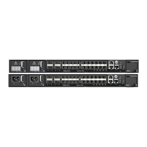
AS7515-24X
1.
AS7515-24X (includes 2 PSUs and 1 fan tray)
2.
Rack Mounting Kit—2 brackets and 8 screws
3.
Grounding kit—grounding lug, 2 screws, and 2 washers
1
2
1.
2 x DC or AC PSUs
2.
4 x 100G QSFP28 ports
3.
20 x 25G SFP28 ports
4.
Product tag
5.
System LEDs
6.
Management ports: 1000BASE-T RJ-45, RJ-45 console
1
1.
QSFP28 Port LEDs:
Green — 100G
Cyan — 50G
Magenta — 40G
Blue — 25G
Yellow — 10G
FRU Replacement
PSU Replacement
1.
Remove the power cord.
2.
Press the release latch and
remove the PSU.
3.
Install replacement PSU.
Package Contents
1
3
6
7
4
5
8
2
2
2.
SFP28 Port LEDs:
Blue — 25G
Green — 10G
Cyan — 1G
Fan Tray Replacement
1.
Press the fan tray's release
latch.
2.
Pull out to remove the tray.
3.
Install replacement tray with
matching airflow direction.
2
3
4.
Ring lugs (x4) (included with DC PSUs only)
5.
(Optional) AC power cord
6.
Documentation—Quick Start Guide (this document) and Safety
and Regulatory Information
Overview
10
9
7.
Timing ports: GNSS, ToD/1PPS RJ-45, 10MHz, 1PPS
8.
Reset button
9.
USB storage port
10.
Fan tray
11.
Grounding screw
Status LEDs
3
3.
System LEDs:
LOC — Blinking Blue (device locator)
DIAG — Green (OK), Orange (fault detected)
PSU1/2 — Green (OK), Amber (fault)
FAN — Green (OK), Orange (fault)
4.
RJ-45 Management Port LEDs: Left (link), Right (activity)
– 1 –
www.edge-core.com
4
5
4
E092024-CS-R01
150200002786A
6
11
4
Advertisement

Related Manuals for Edge-Core AS7515-24X


Summary of Contents for Edge-Core AS7515-24X
- Page 1 Cell Site Gateway www.edge-core.com AS7515-24X Package Contents AS7515-24X (includes 2 PSUs and 1 fan tray) Ring lugs (x4) (included with DC PSUs only) Rack Mounting Kit—2 brackets and 8 screws (Optional) AC power cord Grounding kit—grounding lug, 2 screws, and 2 washers Documentation—Quick Start Guide (this document) and Safety...
- Page 2 (ONIE) software installer preloaded, but no software image. surface treatment). Information about compatible software can be found at Attach Grounding Wire www.edge-core.com Attach the grounding wire (#6 AWG/16 mm ) to the grounding point on Note: The drawings in this document are for illustration only the device’s rear panel or side panel.
- Page 3 Quick Start Guide The following transceivers are supported in the SFP28 ports: Caution: Before connecting power supply cables to the 25GBASE-SR device, ensure that power to the feed lines is turned off at the 25GBASE-LR supply circuit breaker or disconnected from the power bus. 10GBASE-SR ...
- Page 4 Quick Start Guide Hardware Specifications Size (WxDxH) 438.4 x 300 x 43.7 mm (17.26 x 11.81 x 1.72 in.) Weight 5.42 kg (11.95 lb), with two installed PSUs Temperature Operating: -40° C to 65° C (-40° F to 149° F) Transportation: -40°...
Need help?
Do you have a question about the AS7515-24X and is the answer not in the manual?
Questions and answers