Advertisement
Quick Links
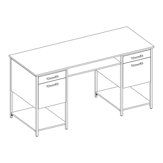
Roca Double Pedestal Desk
ADULT ASSEMBLY REQUIRED DUE TO THE PRESENCE OF SMALL PARTS, SHARP
POINTS, SHARP EDGES AS RECEIVED
If you have any questions regarding assembly or if parts are missing, DO NOT return this item to the store
where it was purchased. Please call our toll-free customer service number and have your instructions and parts
list ready to provide the model name, part name or factory number:
Or visit our web site 24 hours a day, 7 days a week for product assistance at
THIS INSTRUCTION BOOKLET CONTAINS IMPORTANT SAFETY INFORMATION.
Model # SPCA-ROC60DPD
Pacific Standard Time: 8:30 a.m. - 4:30 p.m., Monday - Friday
www.whalenfurniture.com
Or e-mail your request to parts@whalenfurniture.com
PLEASE READ AND KEEP FOR FUTURE REFERENCE.
Date 2024-07-12
1-866-942-5362
Rev. 0001-A
LOT NUMBER:
DATE PURCHASED: /
/
Advertisement

Related Manuals for Whalen Roca SPCA-ROC60DPD


Summary of Contents for Whalen Roca SPCA-ROC60DPD
- Page 1 LOT NUMBER: DATE PURCHASED: / Roca Double Pedestal Desk Model # SPCA-ROC60DPD ADULT ASSEMBLY REQUIRED DUE TO THE PRESENCE OF SMALL PARTS, SHARP POINTS, SHARP EDGES AS RECEIVED If you have any questions regarding assembly or if parts are missing, DO NOT return this item to the store where it was purchased.
- Page 2 M A X I M U M R E C O M M E N D E D W E I G H T L O A D S MANUFACTURER: Whalen Furniture Manufacturing CATALOG : Roca Double Pedestal Desk MODEL # SPCA-ROC60DPD MAXIMUM LOAD 90.7 kg / 200 lb...
- Page 3 IMPORTANT Before you begin: Open, identify and count all parts prior to assembly. Lay out parts on a flat and non-abrasive surface. You will need the parts identified on page 4 and 5 of this instruction manuals. NOTE: IT IS VERY IMPORTANT TO USE GLUE WITH DOWELS. EXCESS GLUE CAN BE WIPED OFF WITH DAMP CLOTH.
- Page 4 Parts and Hardware List Please read completely through the instructions and verify that all listed parts and hardware are present before beginning assembly. A- Desk Top B- Left Cabinet Left Frame (Qty. 1) (Qty. 1) C- Left Cabinet Right Frame D- Right Cabinet Left Frame E- Right Cabinet Right Frame (Qty.
- Page 5 Parts and Hardware List Please read completely through the instructions and verify that all listed parts and hardware are present before beginning assembly. U- File Drawer Right Side V- File Drawer Back Panel W- File Drawer Bottom Panel (Qty. 2) (Qty.
- Page 6 Utility Drawer Assembling Grooves line up with each other and face inward. NOTE: Please do not fully tighten all bolts and screws until you finish assembling all parts. Once assembled, go back and fully tighten all bolts and screws. This will make the assembly easier. 1.
- Page 7 Utility Drawer Assembling 6. Securely screw eight Self Tapping Cam Bolts (3) into the designated small holes on the Utility Drawer Front Panels (N) using a Phillips screwdriver. NOTE: Screw-in cam bolts must be screwed down flush. DO NOT over tighten the cam bolts. 7.
- Page 8 Utility Drawer Assembling 9. Turn the previous assembly upright and install one Handle (Z) to the front of each Utility Drawer Front Panel (N) with two 30 mm Handle Bolts (13). 10. Glue sixteen Small Wood Dowels (5) into the inner holes on the File Drawer Side Panels (T and U) and Back Panels (V) as shown.
- Page 9 File Drawer Assembling Grooves line up with each other and face inward. 11. Orient and attach one File Drawer Back Panel (V) between the File Drawer Side Panels (T and U) with four 38 mm Screws (12). 12. Repeat this step to assemble an additional drawer assembly. 13.
- Page 10 File Drawer Assembling 15. Securely screw eight Self Tapping Cam Bolts (3) into the designated small holes on the File Drawer Front Panels (S) using a Phillips screwdriver. 16. Position one File Drawer Front Panel (S) onto the inserted Small Wood Dowels (5) on the File Drawer Side Panels (T and U) and fasten it in place by engaging four Small Cam Locks (1).
- Page 11 File Drawer Assembling 18. Turn the assembled file drawers upright and install one Handle (Z) to the front of each File Drawer Front Panel (S) with two 30 mm Handle Bolts (13). The high side faces inward. 19. Position two Guide Rails (X) onto both File Drawer Side Panels (T and U) with the higher side facing inward.
- Page 12 Assembly Instructions 22. Glue twelve Large Wood Dowels (6) into the inner holes on the Cabinet Back Panels (F) and Cabinet Bottom Panels (G). 23. Securely screw eight Cam Bolts (4) into the designated threaded holes on the back post of Left Cabinet Side Frames (B and C) and Cabinet Back Stretchers (L).
- Page 13 Assembly Instructions 24. Securely screw six Self Tapping Cam Bolts (3) into the designated small holes on both Left Cabinet Side Frames (B and C) using a Phillips screwdriver. The cam lock housings face inward. 25. Orient and attach one Cabinet Back Panel (F) to one Cabinet Bottom Panel (G) with two 38 mm Screws (12). 26.
- Page 14 Assembly Instructions The mounting holes face inward. 27. Orient and attach the Cabinet Back Stretchers (L) to the Cabinet Back Panels (F) respectively by engaging four Large Cam Locks (2). 28. Align and attach one previous assembly to the Left Cabinet Left Frame (B) by engaging five Large Cam Locks (2).
- Page 15 Assembly Instructions 29. Fasten the assembled Cabinet Back Stretcher (L) to the Left Cabinet Left Frame (B) using one M6 x 15 mm Bolt (7), one Lock Washer (8) and one Flat Washer (9). 30. Fit one Cabinet Front Stretcher (M) onto the U-shaped bracket properly and fasten it in place with one M6 x 15 mm Bolt (7), one Lock Washer (8) and one Flat Washer (9).
- Page 16 Assembly Instructions 32. Using the pilot holes as a guide, install four Metal Brackets (15) to the corners of each Cabinet Bottom Shelf (H) using eight 12 mm Screws (10). Make sure that the right-angle sides are flush with the short edges of the Cabinet Bottom Shelf.
- Page 17 Assembly Instructions 7 8 9 35. Lift the previous assembly upright and position it near the final location. 36. Fasten the Cabinet Stretchers (L and M) to U-shaped brackets on the Left Cabinet Right Frame (C) using two M6 x 15 mm Bolts (7), two Lock Washers (8) and two Flat Washers (9). 37.
- Page 18 Assembly Instructions 38. Securely screw three Self Tapping Cam Bolts (3) into the designated small holes on the Left Cabinet Right Frame (C) using a Phillips screwdriver. 39. Securely screw four Cam Bolts (4) into the threaded holes on the back posts of both Right Cabinet Side Frames (D and E).
- Page 19 Assembly Instructions 40. Securely screw six Self Tapping Cam Bolts (4) into the designated small holes on the Right Cabinet Side Frames (D and E) using a Phillips screwdriver. 41. Align and attach the assembled Cabinet Back Panel (F) and Cabinet Bottom Panel (G) to the Right Cabinet Left Frame (D) by engaging five Large Cam Locks (2).
- Page 20 Assembly Instructions 42. Fasten the assembled Cabinet Back Stretcher (L) to the Right Cabinet Left Frame (D) using one M6 x 15 mm Bolt (7), one Lock Washer (8) and one Flat Washer (9). 43. Fit the other Cabinet Front Stretcher (M) onto the front U-shaped bracket on the Right Cabinet Left Frame (D) properly and fasten it in place with one M6 x 15 mm Bolt (7), one Lock Washer (8) and one Flat Washer (9).
- Page 21 Assembly Instructions 45. Tilt and fit the other Cabinet Bottom Shelf (H) between the posts of the Right Cabinet Side Frames (D and E). Make sure that the center of mounting holes of the Metal Brackets (15) overlap the bottom threaded sockets properly.
- Page 22 Assembly Instructions 49. Securely screw two Cam Bolts (4) into the designated threaded holes on the Right Cabinet Left Frame (D) using a Phillips screwdriver. 50. Securely screw three Self Tapping Cam Bolts (3) into the designated small holes on the Right Cabinet Left Frame (D) using a Phillips screwdriver.
- Page 23 Assembly Instructions 51. Glue eight Large Wood Dowels (6) into the inner holes on the Modesty Panel (I) and Middle Fixed Shelf (J). 52. Securely screw six Self Tapping Cam Bolts (3) into the designated small holes on the Desk Top (A) and Modesty Panel (I) using a Phillips screwdriver.
- Page 24 Assembly Instructions The cam lock housings face the bottom edge without cable channel run against. 53. Orient and attach the Middle Fixed Shelf (J) to the Modesty Panel (I) by engaging and tightening three Large Cam Locks (2). 54. Align and attach the assembled Middle Fixed Shelf (J) between the Side Frames (C and D) by engaging and tightening six Large Cam Locks (2).
- Page 25 Assembly Instructions 55. Fasten the Middle Stretcher (K) between the Side Frames (C and D) with four M6 x 15 mm Bolts (7), four Lock Washers (8) and four Flat Washers (9). B/C/D/E 56. Using the wood dowels inserted on the Modesty Panel (I) as a guide, ask for assistance to place the Desk Top (A) on the previous assembly properly.
- Page 26 Assembly Instructions 58. Insert seven Large Cam Locks (2) into the large holes in the Modesty Panel (I), making sure that the arrow on the face of the cam lock faces out and points towards the holes on the closest end. Turn the cam locks with a Phillips screwdriver until securely locked onto the cam bolts.
- Page 27 Assembly Instructions DL/DR CL/CR 62. To insert the Utility Drawers to the frame, tip the front of drawer down and drop the rollers of the drawer slide runners behind the rollers of slide tracks on the unit. Lift the front of the drawer up and slide it into the unit.
- Page 28 Assembly Instructions 64. Affix the Paper Stickers (16) onto the visible cam locks to conceal the cams. Legal size file folders hang on the file Letter size file folders hang hangers (Y). Slide file hangers forward directly on the guide rails (X). or backward to adjust size according to Arrange from front to back to your folder dimensions.
- Page 29 Assembly Instructions Wall Wooden stud Wall Metal bracket Long screw Short screw Connector Wall B/C/D/E Steel cable Floor leveler Tools required (not included): Phillips screwdriver, stud finder, tape measure, pencil, power drill and 1/8” drill bit. 66. Ask for assistance to position the assembled unit at the desired location against a wall. Adjust each floor leveler pre-installed under the side frames (B, C, D and E) as necessary until the Desk Top is level.
- Page 30 FURNITURE TIPPING RESTRAINT YOUNG CHILDREN MAY BE INJURED BY TIPPING FURNITURE AND YOU MUST USE THIS TIPPING RESTRAINT TO ATTACH THIS UNIT TO THE WALL, TO PREVENT ACCIDENTS AND/OR INJURIES. THIS HARDWARE, MUST BE PROPERLY INSTALLED (FOLLOW ALL DIRECTIONS IN ORDER ON THIS INSTRUCTIONS), TO PROVIDE PROTECTION AGAINST THE UNEXPECTED TIPPING OF FURNITURE DUE TO IMPROPER USE.
- Page 31 Should this product be defective in workmanship or materials or fail under normal use, we will repair or replace it for up to one (1) year from date of purchase. Every Whalen Furniture product is designed to meet your highest expectations.
Need help?
Do you have a question about the Roca SPCA-ROC60DPD and is the answer not in the manual?
Questions and answers