Advertisement
Quick Links
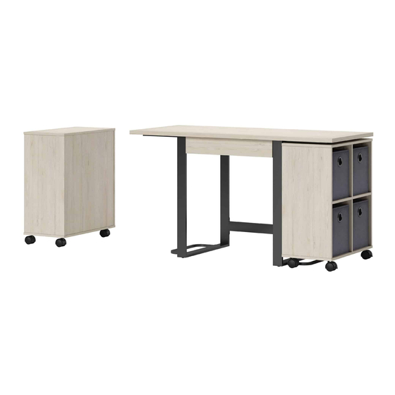
Springfield Modular Desk with Set
ADULT ASSEMBLY REQUIRED DUE TO THE PRESENCE OF SMALL PARTS, SHARP
POINTS, SHARP EDGES AS RECEIVED
If you have any questions regarding assembly or if parts are missing, DO NOT return this item to the
store where it was purchased. Please call our toll-free customer service number and have your
instructions and parts list ready to provide the model name, part name or factory number:
Or visit our web site 24 hours a day, 7 days a week for product assistance at
THIS INSTRUCTION BOOKLET CONTAINS IMPORTANT SAFETY INFORMATION.
of Bookcases
Model # SPLS-SPMDBK-HW
Pacific Standard Time: 8:30 a.m. - 4:30 p.m., Monday - Friday
www.whalenfurniture.com
Or e-mail your request to parts@whalenfurniture.com
PLEASE READ AND KEEP FOR FUTURE REFERENCE.
Date 2021-02-04
1-866-942-5362
Rev. 0001-A
LOT NUMBER:
DATE PURCHASED: /
/
Advertisement

Related Manuals for Whalen Springfield SPLS-SPMDBK-HW


Summary of Contents for Whalen Springfield SPLS-SPMDBK-HW
- Page 1 LOT NUMBER: DATE PURCHASED: / Springfield Modular Desk with Set of Bookcases Model # SPLS-SPMDBK-HW ADULT ASSEMBLY REQUIRED DUE TO THE PRESENCE OF SMALL PARTS, SHARP POINTS, SHARP EDGES AS RECEIVED If you have any questions regarding assembly or if parts are missing, DO NOT return this item to the store where it was purchased.
-
Page 2: Special Note
M A X I M U M R E C O M M E N D E D W E I G H T L O A D S MANUFACTURER: Whalen Furniture Manufacturing CATALOG: Springfield Modular Desk with Set of Bookcases MODEL # SPLS-SPMDBK-HW MAXIMUM LOAD 90.7 kg / 200 lb. - Page 3 IMPORTANT Before you begin: Open, identify and count all parts prior to assembly. Lay out parts on a flat and non- abrasive surface. You will need the parts identified on page 5, 6 and 7 of this instruction manuals. NOTE: IT IS VERY IMPORTANT TO USE GLUE WITH DOWELS.
- Page 4 FURNITURE TIPPING RESTRAINT YOUNG CHILDREN MAY BE INJURED BY TIPPING FURNITURE AND YOU MUST USE THIS TIPPING RESTRAINT TO ATTACH THIS UNIT TO THE WALL, TO PREVENT ACCIDENTS AND/OR INJURIES. THIS HARDWARE MUST PROPERLY INSTALLED (FOLLOW DIRECTIONS IN ORDER ON THIS INSTRUCTIONS), TO PROVIDE PROTECTION AGAINST THE UNEXPECTED TIPPING OF FURNITURE DUE TO IMPROPER USE.
- Page 5 Parts and Hardware List Please read completely through the instructions and verify that all listed parts and hardware are present before beginning assembly. A- Desk Top (Qty. 1) B- Left Side Frame (Qty. 1) C- Right Side Frame (Qty. 1) D- Lower Back Stretcher (Qty.
- Page 6 Parts and Hardware List Please read completely through the instructions and verify that all listed parts and hardware are present before beginning assembly. M- Bookcase Back Panel N- Bookcase Upper Partition Panel O- Bookcase Lower Partition Panel (Qty. 2) (Qty. 2) (Qty.
- Page 7 Parts and Hardware List Please read completely through the instructions and verify that all listed parts and hardware are present before beginning assembly. (1) Small Cam Lock (2) Large Cam Lock (3) Cam Bolt (Qty. 3+1 extra) (Qty. 47+2 extra) (Qty.
- Page 8 Assembly Instructions NOTE: Please do not fully tighten all bolts until you finish assembling all parts. Once assembled, go back and fully tighten all bolts. This will make the assembly easier. 1. Unpack the unit and confirm that you have all the hardware and required parts. Assemble the unit on a carpeted floor or the empty carton to avoid any scratch.
- Page 9 Assembly Instructions The Cam Lock faces outward 4. Align and attach the Drawer Bottom Support (U) to the Drawer Front Panel (P) by engaging one Small Cam Lock (1). (Refer to page 3 on Cam Lock system operation supplement). Grooves line up with each other and face inward 5.
- Page 10 Assembly Instructions 6. Slide the Drawer Bottom Panel (T) into the grooves between the Drawer Side Panels (Q and R) until fully inserted into the groove of the Drawer Front Panel (P). Groove 7. Fasten the Drawer Back Panel (S) to the Drawer Side Panels (Q and R) and the Drawer Bottom Support (U) with six 32 mm Screws (7).
- Page 11 Assembly Instructions 8. Securely screw the Cam Bolts (3) into the designated small holes on the Bookcase Top Panels (H), Bookcase Side Panels (J and K) and Bookcase Middle Shelves (L) with a Phillips screwdriver. DO NOT overtighten the Cam Bolts. 9.
- Page 12 Assembly Instructions 10. Securely screw the Cam Bolts (3) into the designated small holes on the Bookcase Middle Shelves (L) with a Phillips screwdriver. 11. Attach the Bookcase Partition Panels (N and O) to the Bookcase Middle Shelves (L) by engaging two Large Cam Locks (2).
- Page 13 Assembly Instructions The cam lock holes and pilot holes point in the same direction. 13. Align the inserted dowels of previous assembly (L, N and O) with the hole of the Bookcase Back Panels (M) and press them together. 14. Glue the large Wood Dowels (5) into the inner holes on the Bookcase Back Panels (M).
- Page 14 Assembly Instructions 15. Glue the Large Wood Dowels (5) into the inner holes on the Bookcase Side Panels (J and K). The cam lock holes and pilot holes point in the same direction. 16. Attach the Bookcase Side Panels (J and K) to the Bookcase Middle shelves (L) and the Bookcase Back Panels (M) by engaging four Large Cam Locks (2) per Side Panel.
- Page 15 Assembly Instructions J/K/N 17. Attach the Bookcase Top Panels (H) to the previous assembly by engaging six Large Cam Locks (2) per top panel. 18. Using the inserted wood dowels as a guide, fasten each Bookcase Bottom Panel (I) to the assembled units with nine 32 mm Screws (7).
- Page 16 Assembly Instructions 19. With the pilot holes as a guide, attach two Locking Casters (X) to the front and attach two Swivel Casters (Y) to the back of the Bookcase Bottom Panel (I), using four 15 mm Pan Head Screws (6) per caster.
- Page 17 Assembly Instructions 21. Unfold the Storage Baskets (V) and then place the Basket Flooring (W) inside the opened basket to ensure it remains square. Position the Storage Baskets onto the compartments. Unlock Lock 22. Adjust the brake on the two front Locking Casters (X) as shown to lock or unlock the storage unit.
- Page 18 Assembly Instructions 23. Securely screw the Cam Bolts (3) into the designated small holes on the Desk Top (A) and Side Frames (B and C) as shown with a Phillips screwdriver. 24. Securely screw the Cam Bolts (13) into the designated small holes on the Side Frames (B and C) as shown with a Phillips screwdriver.
- Page 19 Assembly Instructions The Cam Locks face downward when the unit is turned upright. The cam locks holes for Desk Top are located at up and face inward. 25. Glue two large Wood Dowels (5) into the pre-drilled holes on the top edge of the Upper Back Stretcher (F).
- Page 20 Assembly Instructions 30. Attach twoStabilizers (E) to the Side Frames (B and C) using eight 15 mm Bolts (8) and eight Washers (10 and 11). Ball bearing cart FRONT FRONT Ball bearing cart 31. Ask for assistance to stand the unit upright and position at the desired location. 32.
- Page 21 Assembly Instructions 33. Combine the two bookcases with the assembly desk as shown.
- Page 22 Assembly Instructions Wooden stud Wall Short screw Wall Metal bracket Metal bracket Nylon strap Long screw Floor leveler Tools required (not provided): Phillips screwdriver, stud finder, tape measure, pencil, power drill and 1/8” drill bit. 34. Position the unit at the desired location against a wall. If necessary, adjust the Floor Levelers at the bottom of the Side Frames (B and C) to level the unit.
-
Page 23: Care And Maintenance
Should this product be defective in workmanship or materials or fail under normal use, we will repair or replace it for up to one (1) year from date of purchase. Every Whalen Furniture product is designed to meet your highest expectations. We guarantee that you will immediately see the value of our fine furniture.
Need help?
Do you have a question about the Springfield SPLS-SPMDBK-HW and is the answer not in the manual?
Questions and answers