Advertisement
Quick Links
Installation and operating
manual
Refrigeration Dryer Series
RDP 3400 W ES
Please read the following instructions carefully before installing the product. Trouble free and
safe operating of the product can only be guaranteed if recommendations and conditions stated
in this manual are respected.
Advertisement

Related Manuals for OMEGA AIR RDP 3400 W ES


Summary of Contents for OMEGA AIR RDP 3400 W ES
- Page 1 Installation and operating manual Refrigeration Dryer Series RDP 3400 W ES Please read the following instructions carefully before installing the product. Trouble free and safe operating of the product can only be guaranteed if recommendations and conditions stated in this manual are respected.
- Page 2 Dear customer! Thank you for purchasing our product. In order for the product to serve well and reliably, please read these installation and operating instructions carefully. In order to avoid misuse of equipment and potential hazards for the operator, please read thoroughly and strictly follow the instructions contained in this installation and operating manual.
- Page 3 Table of Contents 1. GENERAL INFORMATION ..........................5 1.1. Device information ........................5 1.2. Information on the supplier ......................5 1.3. Refrigeration air dryers ....................... 6 1.4. Proper use ............................ 6 1.5. Efficiency ............................6 1.6. Data plate ............................. 7 2.
- Page 4 5.9. Expansion valve with XEV22D drive ..................23 5.10. Hot gas bypass valve ........................ 24 6. TRANSPORT ..............................25 7. STORING / REMOVE FROM USE ........................25 8. INSTALLATION ............................26 8.1. General environment requirements ..................26 8.2. Compressed air quality and connection ................... 26 8.3.
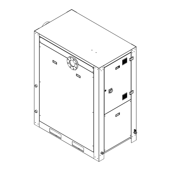
- Page 5 1. GENERAL INFORMATION 1.1. Device information Data plate is located on the back of the device (Figure 1). It contains important data regarding the model, serial number, working conditions and refrigerant used. Always refer to this data when contacting the manufacturer or sales representative. Model of refrigeration air dryer: Serial number: Year of manufacture:...
- Page 6 1.3. Refrigeration air dryers Compressed air contains contaminants such as water, oil and particles. Impurities need to be removed or their concentration reduced to an acceptable level according to the requirements of the application. The ISO 8573-1 standard specifies the purity / quality of the air for contaminants. The humidity (water vapor content) can be expressed in terms of Pressure Dew Point (PDP).
- Page 7 1.6. Data plate Data plate contains important information of the device. It is located on the back of the dryer. It is important to provide the information on the data plate when contacting your sales representative or manufacturer. Information on the data plate includes but is not limited •...
- Page 8 2.1. Safety symbols and signal words used Operating instructions must be observed General hazard High voltage hazard Hot surface hazard General requirement Do not use water to extinguish the fire Imminent hazard Danger! Non observance will result in serious injury or death and/or property damage Potential hazard Warning! Non observance could result in serious injury, death and/or property damage...
- Page 9 2.2. General safety instructions Danger! Compressed Air! • Improper use of the compressed air system can lead to serious injury or death. • Before working on the dryer ensure the dryer is vented and not under pressure (this also applies the closest components of the compressed air installation around the dryer).
- Page 10 Caution! Improper use! • Only use refrigeration air dryers for intended purpose. • Improper handling (transport, installation, use, maintenance) of a refrigeration air dryer can lead to serious injury or death. The result of improper use may be damage to the device and/or reduced efficiency of the dryer.
- Page 11 3. Technical Specifications 3.1. Components Figure 2 Components 6. Hot gas bypass valve in 1 1. Heat exchanger 3 2. Condenser 7. Main power switch 3. Compressor 8. Capillary tube 4. Condensate drain 9. Temperature sensor 5. Controller 10. Filter / dehydrator 3.2.
- Page 12 MATERIALS Casing Carbon steel Casing corrosion protection Epoxy powder paint Evaporator Brazed plate stainless steel (RDP 600-1900), aluminum (RDP 20-480, RDP 2600) Evaporator insulation Flexible elastomeric foam Condenser Aluminum fin and copper tube (RDP 20-1900), aluminum MCHE (RDP 2600) Compressor Carbon steel Refrigerant piping Copper...
- Page 13 3.3. Standard parameters and correction factors PERFOMANCE DATA PER ISO 7183:2007 Ambient temperature 25 °C / 77 °F Inlet pressure 7 bar / 102 psig Inlet relative humidity 100 % Inlet temperature 35 °C / 95 °F To calculate the correct capacity of a given dryer based on actual operating conditions, multiply the nominal inlet flow by the appropriate correction factor(s).
- Page 14 4. Refrigeration air dryer operation The refrigeration air dryer is designed to remove moisture from the input air to achieve the desired dew point at the exit. All refrigeration air dryers described above operate according to the same principle. The operation of the refrigeration air dryer can be divided into two main circuits: Air and refrigeration circuit.
- Page 15 5. Refrigeration air dryer components 5.1. Compressor with frequency converter The compressor sucks the gaseous phase of the refrigerant from the evaporator (low pressure side) and compresses it to the condensation pressure (high pressure side). Built-in compressors are manufactured by leading manufacturers and are designed for applications where high compression ratios and high temperature differences are present.
- Page 16 maximum heat transfer. A large cross-section of the flow channel in the heat exchanger 3in1 provides low speed and low-pressure losses. The large dimensions of the heat exchanger air / refrigerant and the counter-flow design enable the complete evaporation of the refrigerant (preventing the return of the liquid to the compressor).
- Page 17 LEDS STATUS DESCRIPTION Compressor off Compressor on BLINKING Compressor stopped due to time protection Fan off Fan on BLINKING No function No function / Condensate drain closed (units with timer-controlled drains) No function / Condensate drain open (units with timer-controlled drains) BLINKING No function Normal operation...
- Page 18 OPERATION AND DISPLAY Standby mode: The dryer is in standby mode. The compressor and fan(s) are off. In case compressor oil heater is installed the heater is on. Press for 3 seconds to start the dyer. Press for 3 seconds to load default parameters. Press to show firmware release.
- Page 19 ALARMS Dew point sensor failure. Permanent alarm. The dryer will not start/work. Compressor temperature sensor failure. Permanent alarm. The dryer will not start/work. Condenser temperature failure. Permanent alarm. The dryer will not start/work. Compressor temperature ≥ 105 °C. Possible compressor damage. The dryer will enter in special alarm operation to prevent freezing and damage of the evaporator.
- Page 20 MODBUS COMMUNICATION For MODBUS communication the RS485 adapter is needed. The twisted pair of cables needs to be connected to A and B. The default address for the MODBUS communication is 1. This can be changed through parameter 14. MODBUS SETTINGS BAUD RATE 9600 WORD LENGTH...
- Page 21 Default Range Press Press Press parameter Function number Drain Cycle Value Go to following Increase Decrease 1 – 10 s parameter value value Drain Period Value Go to following Increase Decrease 0 - 600 s parameter value value Do not change Go to following Increase Decrease...
- Page 22 5.5. Condensate drain Caution! Compressed air Before performing any maintenance on the drain ensure the dryer is vented and not under pressure. AUTOMATIC MECHANICAL CONDENSATE DRAIN Automatic mechanical condensate drain has been developed for fully automatic discharging of condensate from the compressed air system. Condensate accumulates in reservoir and when the level is high enough condensate is being discharged from the system without any compressed air loss.
- Page 23 5.7. Safety functions Safety functions are implemented in the controller. For the protection against low and high pressure the high- and low-pressure switches are added (RDP/T 750 – 2600) LPS: Low-pressure protection device on the suction side of the compressor trips, if the pressure drops below the pre-set value.
- Page 24 5.10. Hot gas bypass valve This valve works as capacity regulator. It adapts compressor capacity to actual evaporator load maintaining a constant temperature / pressure of the evaporator at about +2 °C. Fitted between the high- and low-pressure sides of the air-dryer refrigerant system maintain constant compressor suction pressure by injecting hot gas from the high-pressure side.
- Page 25 6. Transport • Check the packaging and dryer for any visible damage. The refrigeration dryer can be damaged during transport. Operating such dryer may result in injury or death. In case of visual damage report the damage to the delivery carrier and contact manufacturer/supplier. •...
- Page 26 8. Installation 8.1. General environment requirements The following location requirements must be met for the dryer to operate properly: • Clean and dry space protected against atmospheric conditions. • The installation area must be even and able to bear the weight of the dryer. •...
- Page 27 Caution! Contaminated compressed air! Contaminated air can reduce refrigeration dryer efficiency and performance. In worst case it can clog the heat exchanger and permanently damage the dryer. 8.3. Electrical connection Adequate power supply needs to be provided. See the data plate on the dryer. Voltage tolerance is ±10 % It is mandatory for the dryer to be grounded.
- Page 28 8.5. Installation arrangement Two most common installation arrangements of the refrigeration dryer are presented in Figure 9 Installation arrangements. They are not mandatory and are presented just as sample. A different arrangement of components is always possible. Type A installation is recommended when the compressor operates at a reduced interruption rate and total consumption that equals the flow of the compressor.
- Page 29 8.6. Installation procedure • The refrigeration air dryer is typically delivered on the standard pallet on which it is screwed with four screws. • The refrigeration air dryer can be lifted with forklift trucks. • Remove the screws and the pallet before positioning the dryer at the desired location. •...
- Page 30 9. Start-up and shut down 9.1. Before start-up This dryer has been fully tested, packaged and checked before shipping. Nevertheless, it may happen that it is damaged during transport. Before starting it up for the first time, check its compliance, and for the first few hours of operation, you should also carefully monitor its behavior.
- Page 31 10. Maintenance During the maintenance work on the refrigeration air dryer, turn it off and wait for at least 30 minutes for it to cool down. Some components can reach high temperature during operation. Avoid contact with these components until they completely cool down. Daily check that the dew point shown on the controller is appropriate.
- Page 32 12. Troubleshooting Danger! Troubleshooting and maintenance procedures can only be performed by qualified personnel with the necessary knowledge. Before any maintenance or service parts make sure that: • no part or device is powered and must not be connected to a power source •...
- Page 33 SYMPTOM POSSIBLE CAUSE PROPOSED ACTIONS Condensate not drained Check the corresponding point Low dew point (condensate Check the corresponding point is freezing inside the Excessive pressure evaporator and obstruct drop the air flow) Piping connections and Check the piping connections and valves valves Check the dryer status (standby mode, alarm, Air dryer does not work...
- Page 34 SYMPTOM POSSIBLE CAUSE PROPOSED ACTIONS Assure nominal operating conditions Thermal overload Ambient temperature too high High compressor discharge temperature or Inlet temperature too high The condenser is dirty Check the corresponding point The fan does not work Get in touch with an engineer in the field of Refrigerant leakage refrigeration.
- Page 35 13. Warranty The warranty is valid for 12 months from the date of purchase and no more than 14 months from the date of dispatch. During this time, the parts that were originally incomplete will be repaired or replaced free of charge. This does not include travel costs, accommodation and food for our technicians.
- Page 36 14. Spare parts Code Description 1401539 COMPRESSOR 1401541 FREQUENCY CONVERTER 2002044 EVAPORATOR 2100361 OIL HEATER 2101783 PROBE PT5N 2101897 DRIVER XEV 22 D DIXELL 2101898 PROBE PP011 4..20mA; 1/4saef 2102077 WATER VALVE 2102259 CONTROLLER RDC 4.0 2102260 WATER - REFRIGERATN HEAT EXCHANGER 2204749 HOT BYPASS VALVE 2204772 EXPANSION VALVE 2300925 FILTER DRIER...
- Page 37 15. Drawing...
- Page 38 16. Electric diagram...
- Page 41 17. Maintenance notes MAINTENANCE TYPE DATE SIGNATURE NOTES First installation...
- Page 42 MAINTENANCE TYPE DATE SIGNATURE NOTES...
- Page 43 Omega Air d.o.o. Ljubljana Cesta Dolomitskega odreda 10 1000 Ljubljana Slovenia Declares that Product: Refrigeration dryer Model: RDP 3400 W ES Description: Compressed air refrigeration dryer Is in conformity with the following directives: Machinery directive 2006/42/EU ISO 12100:2010, ISO 13857:2019...
- Page 44 OMEGA AIR d.o.o. Ljubljana Cesta Dolomitskega odreda 10, 1000 Ljubljana, Slovenia T: +386 1 200 68 00 | info@omega-air.si | www.omega-air.si...
Need help?
Do you have a question about the RDP 3400 W ES and is the answer not in the manual?
Questions and answers