Table of Contents
Advertisement
Advertisement
Table of Contents

Related Manuals for OMEGA AIR A-DRY Series


Summary of Contents for OMEGA AIR A-DRY Series
- Page 1 Installation and operating manual A-DRY adsorption dryer series Please read the following instructions carefully before installing the product. Trouble free and safe operating of the product can only be guaranteed if recommendations and conditions stated in this manual are respected.
-
Page 3: Table Of Contents
Index 1 GENERAL INFORMATION ..........................5 1.1 D ............................5 EVICE INFORMATION 1.2 S ............................. 5 UPPLIER INFORMATION 1.3 B ................................6 ASICS 1.4 A ............................6 DSORPTION RYERS 1.5 A ..............................6 DSORPTION 1.6 A .............................. 7 PPROPRIATE USE 2 SAFETY INSTRUCTIONS .......................... - Page 4 13.5 R ........................52 EPLACEMENT OF THE NOZZLES 14 TROUBLESHOOTING ..........................53 14.1 C ..............................53 ONTROLLER 14.2 C ............................53 ONTROL ALVES 14.3 L ..............................54 EAKAGE 14.3.1 A leak between the block and the tower ..................54 14.3.2 A leak between the valve and the block ................... 55 14.4 H .............................
-
Page 5: General Information
1 General information 1.1 Device information Adsorption dryer model: Serial number: Year of production: Commissioning date: Type of towers: Left tower serial number: Right tower serial number: Please fill in the fields accordingly. Correct information enables proper and efficient maintenance of the device, selection of spare parts and technical support. 1.2 Supplier information Name: Address:... -
Page 6: Basics
1.3 Basics Compressed air contains contaminants such as water, oil and particulates which must be removed or reduced to the acceptable level based on specific application requirements. Standard ISO8573-1 specifies air purity/quality classes for these contaminants. Humidity (water vapour content) is expressed in the terms of Pressure Dew Point (PDP) where Dew point is the temperature at which air is 100% saturated with moisture. -
Page 7: Appropriate Use
1.6 Appropriate use DRY series desiccant dryers are intended for highly efficient preparation of top quality dry compressed air. This appliance must be used only for the purpose for which it was specifically designed. All other uses are to be considered incorrect. Specifically: •... -
Page 8: Safety Instructions
2 Safety instructions Improper handling of compressed air systems/equipment and electric installations/equipment may result in a serious injury or death Improper handling (transportation, installation, use/operation, maintenance) of DRY series dryer may result in serious injury or death. As a result of improper handling damage or reduced performance can occur. - Page 9 • Before any kind of work on the dryer make sure that it is depressurized (in addition to dryer this also refers to the nearest upstream and downstream part of the installation) and disconnected from power supply. • Do not exceed maximum operating pressure or operating temperature range (see the technical data in this manual or the data sheet).
- Page 10 • Use the original spare parts only. • Use the device for the intended purpose only. • Centre of gravity is positioned relatively high meaning there is a risk of tilting the dryer, which can cause serious injury or even death. •...
-
Page 11: Technical Data
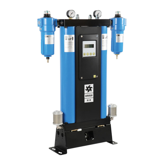
3 Technical data 3.1 Components Part Control valves Note: The adsorption dryer displayed on the pictures of this Consoles manual is A-DRY 6 from A-DRY series adsorption dryer. Tower 1 Tower 2 Controller Pressure indicator Inlet Outlet... -
Page 12: Physical Characteristics
3.2 Physical characteristics CONNECTIONS FLOW CAPACITY DIMENSIONS [mm] WEIGHT MODEL [inch] [scfm] Height Width* Depth [kg] DRY 6 ⅜” 11,5 DRY 12 ⅜” 14,2 DRY 24 ⅜” 14,9 1105 19,3 DRY 36 ⅜” 22,4 1500 24,4 DRY 60 ¾” 37,3 1105 45,0 DRY 75... - Page 13 MATERIALS Consoles Steel Control blocks Aluminium Tower tubes Aluminium Panels Steel Control valve seats Aluminium Non-return valve Aluminium, Steel, PA (polyamide) Sealing Adsorption material Silica gel Corrosion protection Anodized Outside protection Powder paint coated (Epoxy-polyester base) Lubricant Shell cassida grease RLS 2 End-caps Controller Housing CORRECTION FACTORS...
-
Page 14: Pressure Equipment Directive Ped 2014/68/Eu (Fluid Group 2)
3.3 Pressure Equipment Directive PED 2014/68/EU (Fluid group 2) DRY 6/12/24/36/60/75/105/150/200 Category I, Module A Technical datasheet is available. For additional technical specification contact the manufacturer. 3.4 Electrical characteristics Supply voltage 230 V ± 10 % 110 V ± 10 % Supply frequency 50 Hz Power consumption... -
Page 15: Description Of Operation
4 Description of operation Adsorption dryer is intended for removal of vapour from the inlet compressed air in order to reach a desired dew point at the outlet. During normal operation of the adsorption dryer the non-dried compressed air enters the adsorption dryer through the inlet and passes through the appropriate inlet control valve into a tower where the process of adsorption is in progress. -
Page 17: Controller
5 Controller Outlet Left Right Column Column Inlet drain 24Vdc point SENS dig. in Mains 2A F Controller Y1, Y3 – left and right inlet valve Y2, Y4 – left and right purge valve Y6 – drain valve (*) d.p. – dew point sensor (*) * depend of the model... - Page 18 Interface Layout and Menu structure The controller of dryer comprises a display and keys. They are used to show necessary information about dryer state. They enable user to set some working parameters. Next to the display, there are three LED’s, which provide quick information of dryer state. Green Dryer is operational Yellow...
- Page 19 1. Operation 2. Test Cycle ***** TEST CYCLE ***** 2 sec. ◄ ADSORBING IDLE > 09:15 00:00 Press '+' to start! 3. DP Sensor 4. Dew Point Sensor Setting ***** Dew Point **[1] ***** Dew Point ***** 2 sec. ---°C Set Dew Point at Current: 0.0mA...
-
Page 20: Operation
5.1 Operation The Operation Menu shows a momentary state of dryer. In the following Figure, adsorption takes place in the left and regeneration in the right column. Below the label Adsorbing is time that remains for adsorption. Similarly, the time below the label Regenerating is time that remains for regeneration. - Page 21 ADSORBING ► < REGEN. 02:30 12:33 The left column is regenerated. After predefined time, moisture is purged from it and the left purge valve closes. This causes pressure build up in the left column. ADSORBING ► < IDLE 00:00 09:15 After certain time, right column is saturated with water.
-
Page 22: Test Cycle
Power up At power down, current state of adsorption and regeneration is stored in the non-volatile memory of controller. At power up, this information is used so that adsorption starts in the column which contains less moisture. 5.2 Test Cycle One complete cycle of adsorption and regeneration can last. -
Page 23: Dew Point Sensor Setting
Controller 24Vdc 4 – 20mA Outlet Dryer Figure: Connection example of two wires dew point sensor Controller 4 – 20mA Outlet Dryer Figure: Connection example of dew point sensor with its own power supply The corresponding menu displays sensor’s output in mA and in °C. Current measurement helps us to test proper operation of the sensor. -
Page 24: Switch Point
***** Dew Point ***** ***** Dew Point ***** 2 sec. Set Dew Point at Set Dew Point at >4mA: -40°C 4mA: > -40°C 20mA: 20°C 20mA: 20°C ***** Dew Point ***** ***** Dew Point ***** Set Dew Point at Set Dew Point at 4mA: -40°C 4mA:... -
Page 25: Dew Point Alarm
***** Dew Point ***** ***** Dew Point ***** 2 sec. >Switch Point: -40°C Switch Point: > -40°C Mode: Variable Cycle Mode: Variable Cycle ***** Dew Point ***** ***** Dew Point ***** Switch Point: -40°C Switch Point: -40°C >Mode: Variable Cycle Mode:>Variable Cycle ***** Dew Point *****... -
Page 26: Timer Drain
Controller 24Vdc input Dryer SCADA Figure: Example of connection of output to typical SCADA ***** Dew Point ***** ***** Dew Point ***** 2 sec. >Alarm: -30°C Alarm: > -30°C Output: Dryer Active Output: Dryer Active ***** Dew Point ***** ***** Dew Point ***** Alarm: -30°C... -
Page 27: Timer Drain Setting
inlet Dryer Controller drain Figure: Example of connection of output to typical SCADA In this menu, the draining can be triggered manually by pressing cancel key. In the Timer Drain Menu, it is displayed when the condensate is going to be released. If On Period of timer is set to zero, the timer drain function is disabled. -
Page 28: Input/ Output
5.11 Input/ Output This menu displays state of input and outputs. The input displays condition of external switch that pulls the input down. If the switch is closed then the input is displayed set and the dryer operates. If the switch is opened then the input is displayed cleared and the dryer is in standby. -
Page 29: Statistics
**** Input/Output **** **** Input/Output **** 2 sec. Set Standby Mode: Set Standby Mode: >Mode: Finish Cycle Mode: >Finish Cycle **** Input/Output **** Set Standby Mode: Mode: >Direct Stop There are two possible modes of entering standby. It the Finish Cycle mode, dryer completes regeneration and prepare columns for new cycle. -
Page 30: Efficiency Considerations
6 Efficiency considerations Efficiency of the adsorption dryer is primarily dependant on the length of the adsorption cycle time (see Description of operation) and the nozzle dimensions. To ensure the most efficient and economical operation of the adsorption dryer DRY series dryers are supplied in a wide selection of pre-set controller modes and nozzles that correspond to the varying operating conditions specified by the costumers. -
Page 31: Transportation
7 Transportation • Transportation should be done by appropriately qualified personnel. • For transportation please check and follow local regulations for lifting and transportation of heavy cargo. • Provide adequate lifting and transportation equipment. • Centre of gravity in a vertical position is positioned relatively high resulting in a heightened risk of toppling the dryer due to tilting, which can cause serious injury or even death. -
Page 32: Storage
8 Storage To prevent the damage to the dryer during storage make sure that the following requirements are fulfilled: • Dryer can only be stored at a dry and clean indoor location. • During storage ambient temperature must not exceed 1,5°C – 66°C range. For other storage temperatures please contact the manufacturer. -
Page 33: Installation
9 Installation 9.1 Initial inspection Adsorption dryer could be damaged during transportation. Putting a damaged adsorption dryer into operation can result in injury or death! Check the adsorption dryer for any visible damage after removing the packaging. If the adsorption dryer is damaged contact the transportation contractor and supplier. -
Page 34: Installation Layout
9.3 Installation Layout Below are two of the most common installation layouts for adsorption dryer. The schemes specified bellow are not obligatory but only provided as an example. Different arrangement of certain components is always possible. 1. Compressor 2. Aftercooler 3. - Page 35 LAYOUT 1 (Dryer is installed downstream from pressure vessel) • When only partial flow rate of the compressor is treated by the dryer. LAYOUT 2 (Dryer is installed upstream from pressure vessel) • When total flow rate of the compressor is treated by the dryer. •...
-
Page 36: Installation
9.4 Installation • Adsorption dryer should be installed in such a way that it is protected from environmental influences (compressor station). • Install the dryer in the area where people are normally not present because of noise emissions. • Make sure that the adsorption dryer is protected against vibrations and other mechanical stress. - Page 37 (9.1) ±5°...
- Page 38 Console layout for: DRY 6, DRY 12, DRY 24 and DRY 36 (9.2) Console layout for: DRY 60, DRY 75 and DRY 105 (9.3)
-
Page 39: Commissioning
10 Commissioning 10.1 Pressurisation Rapid pressurisation of the dryer can cause pressure blows which can damage the adsorption dryer! Adsorption dryer should be pressurised slowly through an appropriate valve at the inlet. During the pressurisation process the outlet valve should remain closed and the adsorption dryer should not be operational. -
Page 40: Start-Up
10.3 Start-up After the installation, pressurisation and opening of the outlet valve procedures are completed the start-up procedure can be initiated. Follow the start-up procedure: • Visually re-check the installation. • Make certain that the inlet valve is opened. • Check the manometers to make certain that both towers are pressurised. •... -
Page 41: Additional Equipment
12 Additional equipment It is necessary that a condensate separator and a pre-filter be installed at the inlet side and an after-filter at the outlet side! Condensate separator removes liquid water and other liquid content from compressed air flow. Removing liquid water and other liquid content with the condensate separator ensures the efficient drying and long life of the molecular sieve. -
Page 42: Maintenance
13 Maintenance The molecular sieve, the control valves, the non-return valves and dew-point sensor are subject to wear and need to be replaced according to the service intervals specified bellow. PART MAINTENANCE 1 day 1 month 1 year 4 years years Dryer operation INSPECTION... - Page 43 In order to maintain the system efficiency, optimal performance, best air quality and safety these additional rules of proper maintenance should be followed: • Disconnect the adsorption drier from the compressed air system and the electrical power before conducting any maintenance. •...
- Page 44 Contact your supplier to order service kits: KIT DESCRIPTION 1 year silencer replacement kit 06-36 2 x purge exhaust silencer 1 year silencer replacement kid 60-105 2 x purge exhaust silencer 1 year silencer replacement kid 150-200 2 x purge exhaust silencer 4 x replacement control valves 2 x replacement non-return valves 2 year replacement kit 6-36...
-
Page 45: Replacement Of The Molecular Sieve
13.1 Replacement of the molecular sieve 1. Disconnect the adsorption dryer from the compressed air system and the electrical power. 2. Make certain that the adsorption dryer is depressurised. You can check this by inspecting the pressure indicators at the top of the adsorption dryer. Picture (13.3) 3. - Page 46 (13.6) (13.7)
-
Page 47: Replacement Of The Control Valves
13.2 Replacement of the control valves The following procedure describes the replacement of the normally opened inlet control valves and the normally closed purge control valves. Make sure that you do not mix the valves when replacing the control valves since the normally opened and the normally closed valves fit into any control valve position on the block. - Page 48 (13.10) (13.11) Normally open valve Normally closed valve...
-
Page 49: Replacement Of The Non-Return Valves
13.3 Replacement of the non-return valves Replacement of the non-return valves procedure: 1. Disconnect the adsorption dryer from the compressed air system and the electrical power. 2. Make certain that the adsorption dryer is depressurised. You can check this by inspecting the pressure indicators at the top of the adsorption dryer. - Page 50 (13.15)
-
Page 51: Replacement Of The Purge Exhaust Silencers
13.4 Replacement of the purge exhaust silencers Replacement of the purge exhaust silencers: 1. Disconnect the adsorption dryer from the compressed air system and the electrical power. 2. Make certain that the adsorption dryer is depressurised. You can check this by inspecting the pressure indicators at the top of the adsorption dryer. -
Page 52: Replacement Of The Nozzles
13.5 Replacement of the nozzles If the adsorption dryer operating conditions have changed it is recommendable to contact your supplier to consider different nozzles for a more efficient and economic operation. Find more information in the section 6 Efficiency considerations. If the operating conditions have not changed since the commissioning or the last maintenance then continue with the following procedure to replace the nozzles: 1. -
Page 53: Troubleshooting
14 Troubleshooting 14.1 Controller Consult chapter 5 Controller! 14.2 Control Valves When adsorption dryer is not operating properly as described in the section 4 Description of operation and the controller is functioning properly without malfunction then one reason for the malfunction could be the control valves. The functioning of the control valves can be checked during normal operation of the controller. -
Page 54: Leakage
14.3 Leakage DRY adsorption dryers contain several NBR seals that seal the possible gaps between the assembled parts. The most critical seals are O-rings between the blocks and the towers and the control valve membranes that also have the function of the seals. 14.3.1 A leak between the block and the tower A leak between the block and the tower can mostly be fixed by tightening the nutts on the top of the dryer. -
Page 55: A Leak Between The Valve And The Block
(14.5) 14.3.2 A leak between the valve and the block A leak between the valve and the block can mostly be fixed by tightening the screws that attach the valve to the block. If the tightening of the screws does not solve the leakage problem, follow the procedure below: 1. - Page 56 (14.6) (14.7)
-
Page 57: High Pressure Drop
14.4 High pressure drop High pressure drop is pressure drop exceeding 1 bar. High pressure drop can be caused by the following conditions. 14.4.1 Inadequately dimensioned compressor and dryer If the compressor supplying the dryer is smaller than rating of the dryer the pressure drop will occur. -
Page 58: Oil In The Adsorption Dryer
14.4.3 Oil in the adsorption dryer The reason for high pressure drop may be the oil from compressor that saturated and blocked the filters. If the oil comes in contact with adsorbent, it will destroy the the adsorbent. If you see oil on the after-filter the adsorbent is destroyed, in which case the adsorbent should be changed together with filter cartriges. -
Page 59: Clogged Pre-Filter And/Or After-Filter
14.4.6 Clogged pre-filter and/or after-filter Although the service interval for pre-filter and after-filter is 12 months, the filter might have to be changed before the service interval if they are clogged. You can check the status of the filter on the differential pressure indicator on top of each filter housing. 14.4.7 Increased purge flow on one tower Description: Purge flow during one half-cycle is greatly increased compared to the other half-cycle... -
Page 60: Underdiemnsioned Adsorption Dryer
14.5.1 Underdiemnsioned adsorption dryer If the dryer is underdiemnsioned and the volumetric flow through the dryer is much higher than the dryer rating the ammount of molecular sieve for adsorption and the quantitiy of the air that passes through the molecular sieve during regeneration will be too small. Consequently the pressure dew-point could continue to rise towards the point where molecular sieve is saturated and the inlet and outlet dew-point are equal. -
Page 61: Tower Fails To Depressurise
14.5.4 Tower fails to depressurise Description: During normal operation there is a 4 min interval of purge air release when the tower depressurizes in every-half cycle. During a half-cycle there is no regeneration/purge flow interval on one or both towers. Possible causes, inspection and fixing procedure: 1. -
Page 62: Warranty Exclusion
15 Warranty exclusion The guarantee shall be void if: • The operating instructions were not followed with respect to initial commissioning and maintenance. • The unit was not operated properly and appropriately. • The unit was operated when it was clearly defective. •... -
Page 63: Maintenance Record
16 Maintenance record TYPE OF MAINTENANCE DATE SIGNATURE NOTES Commissioned... - Page 65 OMEGA AIR d.o.o. Ljubljana Cesta Dolomitskega odreda 10 SI-1000 Ljubljana, Slovenia T: +386 (0)1 200 68 00 F: +386 (0)1 200 68 50 info@omega-air.si...
Need help?
Do you have a question about the A-DRY Series and is the answer not in the manual?
Questions and answers