Table of Contents
Advertisement
Installation and operating
manual
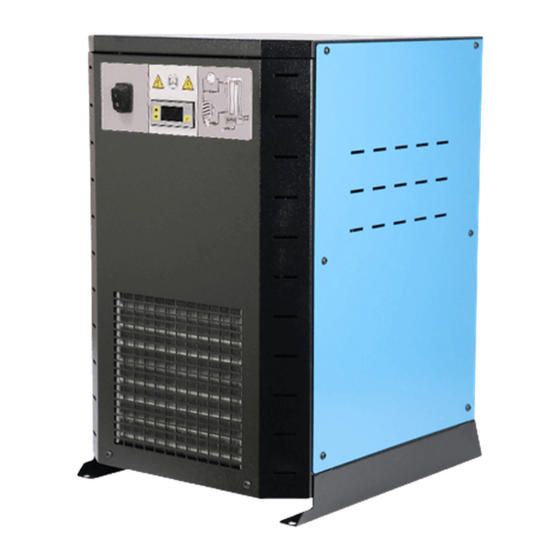
Refrigeration Dryer Series RDP 20 - 2600
Please read the instructions carefully before installation or use. The proper and safe operation of
the refrigeration air dryer is ensured only by following the recommendations and conditions
stated in the instructions.
For additional questions, contact the manufacturer and inform him of the information on the data
plate found on the front of the dryer.
3403165 - MANUAL for RDP 20-2600 - OMEGA AIR_EN_20200618
Advertisement
Table of Contents

Related Manuals for OMEGA AIR RDP Series


Summary of Contents for OMEGA AIR RDP Series
- Page 1 Installation and operating manual Refrigeration Dryer Series RDP 20 - 2600 Please read the instructions carefully before installation or use. The proper and safe operation of the refrigeration air dryer is ensured only by following the recommendations and conditions stated in the instructions. For additional questions, contact the manufacturer and inform him of the information on the data plate found on the front of the dryer.
- Page 2 Dear customer! Thank you for purchasing our product. In order for the product to serve well and reliably, please read these installation and operating instructions carefully. In order to avoid misuse of equipment and potential hazards for the operator, please read thoroughly and strictly follow the instructions contained in this installation and operating manual.
-
Page 3: Table Of Contents
Table of Contents 1 GENERAL INFORMATION ..........................4 1.1. D ............................4 EVICE INFORMATION 1.2. I .......................... 4 NFORMATION ON THE SUPPLIER 1.3 B ................................5 ASIC 1.4. R ..........................5 EFRIGERATION AIR DRYERS 1.5 P ..............................5 ROPER USE 2 SAFETY INSTRUCTIONS .......................... -
Page 4: General Information
16 ELECTRO SCHEMES OF RDP REFRIGERATION AIR DRYER ................36 1 General information 1.1. Device information Model of refrigeration air dryer: Serial number: Year of manufacture: Date of installation: Please fill in the fields carefully. Correct data enables proper and efficient maintenance of the device, selection of suitable spare parts and technical support. -
Page 5: Basic
1.3 Basic Compressed air contains contaminants such as water, oil and particles. Impurities need to be removed or their concentration reduced to an acceptable level according to the requirements of the application. The ISO 8573-1 standard specifies the purity / quality of the air for contaminants. The humidity (water vapor content) can be expressed in terms of Pressure Dew Point (PDP). -
Page 6: Safety Instructions
2 Safety instructions ⚠ Improper use of the compressed air system and electrical installations can lead to injury or death. ⚠ Improper handling (transport, installation, use, maintenance) of a refrigeration air dryer can lead to serious injury or death. The result of improper use may be damage to the device and/or reduced efficiency of the dryer. - Page 7 ⚠ Only use genuine spare parts. ⚠ Only use refrigeration air dryers for intended purpose. ⚠ When transporting the dryer, check and follow the local regulations for lifting and transporting heavy objects. ⚠ In the event of fire, do not use extinguishing water on the dryer and nearby objects. ⚠...
-
Page 8: Technical Specifications
3 Technical Specifications 3.1 Components Figure 2: Components (shown: RDP 100) 1. Heat exchanger 3in1 7. Switch 2. Condenser 8. Capillary tube 3. Compressor 9. Sensor for fan operation 4. Electronic condensate drain 10. Filter / dehydrator 5. Controller 6. Hot gas bypass valve... -
Page 9: Specifications
3.2 Specifications TECHNICAL SPECIFICATIONS Max. operating pressure 14 bar Max. inlet air temperature 55 °C (for temperature ≠ 35 °C apply correction factor) Operating ambient temperature 1,5 °C to 45 °C (for temperature > 25 °C apply correction factor) Pressure dew point + 3 °C Filter requirement (inlet) Prefilter 3 μm... - Page 10 CORRECTION FACTORS To calculate the correct capacity of a given dryer based on actual operating conditions, multiply the nominal inlet flow by the appropriate correction factor(s). CORRECTED CAPACITY = NOMINAL FLOW CAPACITY x C OPERATING PRESSURE DEW POINT [bar] °C [psi] °F 37,4...
-
Page 11: Refrigeration Air Dryer Operation
4 Refrigeration air dryer operation The refrigeration air dryer is designed to remove moisture from the input air to achieve the desired dew point at the exit. All refrigeration air dryers described above operate according to the same principle. The operation of the refrigeration air dryer can be divided into two main circuits: Air and refrigeration circuit. -
Page 12: Refrigeration Air Dryer Components
5 Refrigeration air dryer components 5.1 Compressor The compressor sucks the gaseous phase of the refrigerant from the evaporator (low pressure side) and compresses it to the condensation pressure (high pressure side). Built-in compressors are manufactured by leading manufacturers and are designed for applications where high compression ratios and high temperature differences are present. -
Page 13: Controller Rdc 2
5.4 Controller RDC 2 The controller RDC 2 shows the temperature of the dew point reached by the refrigeration air dryer in the normal operation. By pressing the UP (▲) button, the outlet temperature of the compressor is displayed. By pressing the DOWN (▼) button, the condensation temperature is displayed (the temperature sensor is connected) or the condensation pressure is displayed (the pressure sensor is connected). -
Page 14: Electric Scheme Rdc 2
5.4.1 Electric scheme RDC 2 The controller has 3 outputs (230 V), for compressor, fan and drain. The other outputs are for alarm. The alarm is triggered via opto triac, which can handle 600VAC/50mA. Controller can also be turned OFF/ON via In. Remote. When the current flows, the controller goes to OFF state, when the circuit is disconnected, the controller is in ON state. -
Page 15: Rdc 2 Modbus Communication
5.4.2 RDC 2 MODBUS communication ADDRESS NAME TYPE VARIABLE X UNIT 40013 ADDRESS RDWR Address = X 40014 Service Time R_ONLY Service Time = X 40015 No. of alarms in last 24h R_ONLY Alarm 24 H Number= X 40016 No. of alarms since service R_ONLY Total Alarms = X 40017... -
Page 16: Expansion Valves
5.5 Expansion valves This valve injects a portion of the hot gases (taken from the compressor outlet) into the tube between the evaporator and the suction side of the compressor, thereby maintaining constant temperature / pressure of the evaporator at about +2 °... - Page 17 Troubleshooting errors Troubleshooting and maintenance procedures can only be performed by qualified personnel with the necessary knowledge. Before any maintenance or service parts make sure that: - no part or device is powered and must not be connected to a power source - that no part or device is under pressure and must not be connected to a compressed air system under pressure, - that the maintenance staff fully and accurately read the operating instructions, and in...
-
Page 18: Safety Functions
5.7 Safety functions For protection against low-pressure, the low-pressure switch is added (RDP 750-1900). Other safety functions are implemented in the controller. 5.7.1 Low-pressure switch LPS: Low-pressure protection device on the suction side of the compressor trips, if the pressure drops below the pre-set value. -
Page 19: Efficiency
6 Efficiency The efficiency of the refrigeration air dryer and the desired pressure dew point temperature depends mainly on the right size of the RDP drier. To ensure efficient operation, the RDP refrigeration air dryers are available in a large number of sizes and operating conditions. It is advisable to provide the following information when ordering or technical assistance: •... -
Page 20: Installation
9 Installation 9.1 General requirements for installation The RDP refrigeration air dryer is designed to operate in an environment that ensures the following conditions: • Internal installation, clean and dry space • Non-aggressive atmosphere • The minimum ambient temperature is +1,5 ° C •... -
Page 21: Installation Positioning
9.2 Installation positioning Below are the two most common configurations of installations in which the RDP refrigeration air dryer is installed. The schemes below are not mandatory and they are just a sample. A different arrangement of components is always possible. 1. -
Page 22: Installation Procedure
9.3. Installation procedure • The RDP refrigeration air dryer is typically delivered on the standard pallet on which it is screwed with four screws. • The RDP refrigeration air dryer can be lifted with forklift trucks. • Remove the screws and the pallet before positioning the dryer at the desired location. •... -
Page 23: Start-Up
10 Start-up 10.1 Before start-up Before start-up, check that the operating parameters correspond to the nominal values indicated on the data label of the dryer (frequency, air pressure, air temperature, ambient temperature, ...). This dryer has been fully tested, packaged and checked before shipping. Nevertheless, it may happen that it is damaged during transport. -
Page 24: Maintenance
12 Maintenance During the maintenance work on the refrigeration air dryer, turn it off and wait 30 minutes for it to cool down. Some components can reach high temperatures during operation. Weekly check that the dew point shown on the controller is appropriate. Also check the correct operation of the condensate drainage system. - Page 25 ● The inlet air is too hot. Establish normal operating conditions. ● The inlet pressure is too low. Establish normal operating conditions. ● The flow of inlet air is higher than the flow of the dryer - reduce flow - establish normal operating conditions.
-
Page 26: Spare Parts
14 Spare Parts DESCRIPTION PART NUMBER 100 140 180 235 300 380 480 600 750 1150 1300 1500 1900 1401365 1401437 1401431 1401369 1401439 Compressor 1401440 1401441 1401374 1401375 1401376 1401410 2101729 2101700 Fan & Condenser pack 2101701 2101732 2101802 2101822 Condenser 2101839... -
Page 27: Warranty
15 Warranty The warranty is valid for 12 months from the date of purchase and no more than 14 months from the date of dispatch. During this time, the parts that were originally incomplete will be repaired or replaced free of charge. This does not include travel costs, accommodation and food for our technicians. -
Page 28: Maintenance Notebooks
16 Maintenance notebooks MAINTENANCE TYPE DATE SIGNATURE NOTES First installation... -
Page 30: Drawings Of Rdp Refrigeration Air Dryers
17 Drawings of RDP refrigeration air dryers... - Page 36 16 Electro schemes of RDP refrigeration air dryer RDP 20 - 180...
- Page 37 RDP 235 - 600...
- Page 38 RDP 750- 1900...
- Page 39 RDP 2600...
- Page 40 EC Declaration of Conformity Omega Air d.o.o. Ljubljana Cesta Dolomitskega odreda 10 1000 Ljubljana Slovenia Declares that Product: RDP Model: RDP 20, RDP 35, RDP 50, RDP 75, RDP 100, RDP 140, RDP 180, RDP 235, RDP 300, RDP 380, RDP 480, RDP 600, RDP 750, RDP 950, RDP 1150, RDP 1300, RDP 1500, RDP 1900,...
Need help?
Do you have a question about the RDP Series and is the answer not in the manual?
Questions and answers