Table of Contents
Advertisement
Quick Links
Advertisement
Table of Contents

Related Manuals for OMEGA AIR B-DRY Series


Summary of Contents for OMEGA AIR B-DRY Series
- Page 1 Installation and operating manual B-DRY adsorption dryer series Please read the following instructions carefully before installing the product. Trouble free and safe operating of the product can only be guaranteed if recommendations and conditions stated in this manual are respected.
-
Page 3: Table Of Contents
Index 1 GENERAL INFORMATION ..........................5 1.1 D ............................5 EVICE NFORMATION 1.2 S ............................. 5 UPPLIER NFORMATION 1.3 B ................................5 ASICS 1.4 A ............................6 DSORPTION RYERS 1.5 A ..............................6 DSORPTION 1.6 A ............................. 6 PPROPRIATE 2 SAFETY INSTRUCTIONS ..........................7 3 TECHNICAL DATA ............................ - Page 4 12.6 ) ....................52 HECK ALVE EPLACEMENT PPER LOCK 12.7 ........................53 DSORBENT EPLACEMENT 12.8 D ........................54 POINT ENSOR ALIBRATION 13 TROUBLESHOOTING ..........................55 13.1 C OFF ..........................55 ONTROLLER URNS 13.2 H ............................ 55 RESSURE 13.2.1 Inadequately Dimensioned Compressor and Dryer ................55 13.2.2 The Downstream System is Oversized ....................
-
Page 5: General Information
1 General Information 1.1 Device Information Adsorption dryer model: Serial number: Year of production: Commissioning date: Type of towers: Left tower serial number: Right tower serial number: Please fill in the fields accordingly. Correct information enables proper and efficient maintenance of the device, selection of spare parts and technical support. 1.2 Supplier Information Name: Address:... -
Page 6: Adsorption Dryers
1.6 Appropriate Use B-DRY series desiccant dryers are intended for highly efficient drying of compressed air. This appliance must be used only for the purpose for which it was specifically designed. All other uses are to be considered incorrect. -
Page 7: Safety Instructions
2 Safety Instructions Improper handling of compressed air systems/equipment and electric installations / equipment may result in serious injury or death Improper handling (transportation, installation, use/operation, maintenance) of B- DRY series dryer may result in serious injury or death. As a result of improper handling damage or reduced performance can occur. - Page 8 • Before any kind of work on the dryer make sure that it is depressurized (additional to dryer this also refers to nearest upstream and downstream part of installation) and disconnected from power supply. • Do not exceed maximum operating pressure or operating temperature range (see dryer and vessel type plate;...
- Page 9 • Use the device for the intended purpose only. • Centre of gravity is positioned relatively high meaning there is a risk of tilting the dryer, which can cause serious injury or even death. • For transportation please check and follow local regulations for lifting and transporting heavy objects.
-
Page 10: Technical Data
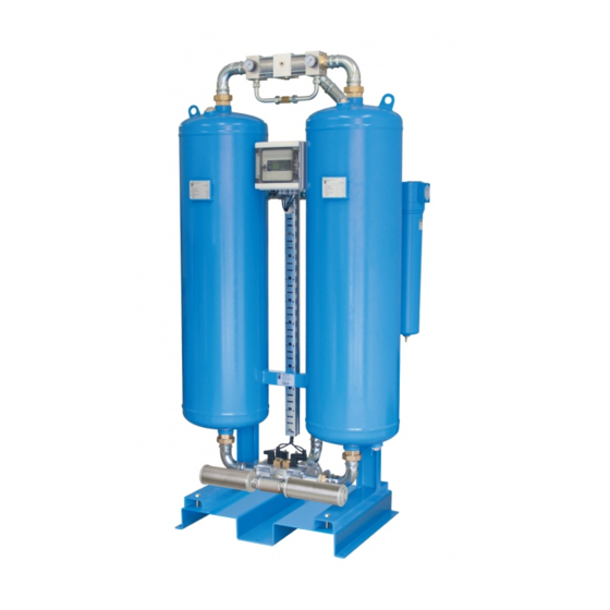
3 Technical Data 3.1 Components Picture 2: Components Note: The adsorption dryer displayed on the pictures of this manual is B-DRY 1000 (left=front view, right=rear view) 1. Vessel 1 (filled with adsorbent) 2. Vessel 2 (filled with adsorbent) 3. Lower valve block 4. -
Page 11: Specifications
3.2 Specifications SIZES Model Conn. Inlet flow Outlet Mass Volum Transient Allowabl IN & flow [mm] [mm] [mm] [kg] pressure e stress Δp [bar] reversals B-DRY 110 G 3/4” 86,0 1657 B-DRY 150 G 1” 117,5 1897 B-DRY 200 G 1” 157,0 1664 B-DRY 250... - Page 12 TECHNICAL PARAMETERS Operating pressure 4 – 16 bar Operating temperature 1,5°C to 60°C Pressure dew points -40°C (-25, -70) Voltage, Frequency 230V, 50/60Hz Power consumption <60W Protection class (controller) IP 65 Noise level (at 1m distance) Normally up to 100dB(A) Filter (inlet)* Super fine coalescing;...
- Page 13 CORRECTION FACTORS To calculate the correct capacity of a given filter based on actual operating conditions, multiply the nominal flow capacity by the appropriate correction factor(s). CORRECTED CAPACITY = NOMINAL FLOW CAPACITY x C OPERATING PRESSURE [bar] [psi] 0,38 0,63 0,75 0,88 1,13...
-
Page 14: Description Of Operation
4 Description of Operation Adsorption dryer is intended for removal of water vapor from the inlet compressed air in order to reach a desired dew point at the outlet. During normal operation of the adsorption dryer the non-dried compressed air enters the adsorption dryer through the inlet and passes through the appropriate inlet control valve into a tower (pressure vessel filled with adsorbent) where the process of adsorption is in progress. -
Page 16: Controller
5 Controller The B-DRY adsorption dryer series controller in combination with tower pressure manometers and the outlet dew-point sensor enables complete monitoring of the adsorption dryer operation. The controller PLC includes a LCD display interface with buttons that enables the technical expert to examine/change settings and operating parameters of the system. -
Page 17: Status Screen
5.1 Status Screen To access the controller interface open the transparent cover on the controller housing. The interface on the PLC block has four buttons and can display the information in four lines. To move through the menu, press the up and down buttons. To enter a sub-menu or confirm an action press right. -
Page 18: Dew-Point Monitoring
- B Y 5.2 Dew-point Monitoring If the dew-point sensor is connected it is possible to monitor the current dew-point. The outlet dew-point sensor is connected to the PLC controller analogue INPUT I7/A1 (0…10VDC, - 100…+20°C) and enables the PLC to adjust the adsorption time of the adsorption-regulation cycle in order to reach a set dew-point. -
Page 19: Times
5.3 Times The CYCLE TIMES SCREEN shows the set adsorption, current adsorption, regulation and current regeneration times. In the first line (ADS) represents the set adsorption time. The second line (T) represents the current time of adsorption. The third line (REG) and the fourth line (T) represent the set regeneration time and the current time of regeneration. -
Page 20: Drain
5.4 Drain The B-DRY adsorption dryer controller has an option to control the drain through the RELAY OUTPUT Q5 (Q1 on the input/output module). The DRAIN screen displays the drain activation interval time (Inter) and its duration (Durat). D R A I Q 5 ) 0 0 m D u r... -
Page 21: Manual Selection Of Fixed Cycle
5.5 Manual Selection of Fixed Cycle It is possible to manually select the fixed cycle mode. If MANUALLY SELECTED FIXED CYCLE is set to ON the adsorption dryer will operate in the fixed cycle mode regardless of dew-point sensor measurements. If MANUALLY SELECTED FIXED CYCLE is set to OFF the adsorption dryer will operate in either VARIABLE CYCLE or FIXED CYCLE mode depending on the conditions. -
Page 22: Lcd Diagram
5.6 LCD Diagram Sensor ON NO Sensor Stand-by signal ↓ ° ° ↓ ↓ Press ↓ for DOWN ↑ for UP ↓ ↓ > > Press ESC +→... -
Page 23: Stand-By
5.7 Stand-by B-DRY series adsorption dryers can receive a stand-by control signal form a compressor. To implement this option INPUT I1 has to be connected to the appropriate control signal on the compressor. For this purpose additional cable glands are available on the controller housing. -
Page 24: Lcd Diagram For Stand-By Feature
S T A N D - g n a l o p s c y c l g o e s S T A N D - B Y . h a n g e E S C + < 5.7.1 LCD Diagram for Stand-by Feature <... -
Page 25: Parameter Settings
5.8 Parameter Settings In VARIABLE MODE the dryer maintains the set dew-point. The dew-point is pre-set according to a specified value. If you wish to set a different dew-point you can set it in Set Parameter section of the CONTROLLER SETTINGS. Additionally the drain output interval and duration times can be set in Set Parameter section. - Page 26 Note! Edit these parameters at your own risk. Edits may cause the dryer to not function properly. Make sure that you understand the effects that editing these parameters will have on the dryer. If DRAIN is selected the following screen will appear. D R A I 1 / 1 1 0 :...
-
Page 27: Lcd Diagram Of Parameter Settings
5.8.1 LCD Diagram of Parameter settings > > > > Stop Program > > > > > Set Parameter Card > > > > > DRAIN B013... -
Page 28: Updating And Reprogramming
5.9 Updating and Reprogramming Updates to the PLC program are not planned and are done under exceptional circumstances. The program update should be provided by manufacturer. Reprogramming with third party programs will void the warranty. To update the controller with Siemens LOGO! 0BA6 follow the instructions bellow. Turn the dryer ON. - Page 29 You need to access the SETTINGS menu. To access the SETTINGS press ↓ until you get to the Date screen. W e d . 0 0 : 0 0 0 1 4 - 0 1 - 0 1 > > N e t w o r >...
- Page 30 Remove the X50 lid and insert SIEMENS LOGO! Memory Card. Program the controller by selecting Load Prog -> Card and pressing OK. Remove the SIEMENS LOGO! Memory Card and reinstall the lid. The update is now complete. Start the controller by pressing ESC and selecting Start. >...
-
Page 31: Electrical Scheme & Sensor Connection
5.10 Electrical Scheme & Sensor Connection... - Page 32 Open the controller box and find the 3 pole connector. Lead the dew-point sensor cable through the gland and connect the wires to the appropriate pins. For two wire 4…20 mA sensor configuration: Supply +: V+ = 24 VDC Signal: I+ = 4…20 mA For three wire 4…20 mA sensor configuration: Supply +: V+ = 24 VDC Supply -: V- = 0 VDC...
-
Page 33: Data Logging
5.11 Data Logging ADC 2.0 controller with Siemens LOGO! 0BA8 PLC has the ability to collect data about the dryer operation. The logger collects the data every 10 s. The data collected includes: Digital inputs Digital outputs Analog input PDP sensor, values 0…1000 PDP sensor value in °Ctd The controller itself has a limited storage capability. -
Page 34: Remote Access
5.12 Remote Access It is possible to monitor the dryer with Siemens LOGO 0BA8 controller through the “LOGO! Web server” application via web browser (Internet Explorer, Chrome, Mozilla) or “LOGO! App” mobile application. The mobile application can be downloaded from Siemens webpage and most mobile app stores. - Page 36 Reserve a static IP address for the dryer and set the IP in the controller settings. Press ↓ until you get to the last screen and then press ESC to enter the settings. > > N e t w o r >...
- Page 37 Enter the password and you will get access to the controller interface.
-
Page 38: Efficiency Considerations
Efficiency of the adsorption dryer is primarily dependent on the length of the adsorption cycle time (see Description of operation) flow velocity and the nozzle dimensions. To ensure the most efficient and economical operation of the adsorption dryer B-DRY series dryers are supplied in a wide selection of pre-set controller modes and nozzles that correspond to the varying operating conditions specified by the costumers. -
Page 39: Transportation
7 Transportation • Transportation should be done by appropriately qualified personnel. • For transportation please check and follow local regulations for lifting and transportation of heavy cargo. • Provide adequate lifting and transportation equipment. • Dryer can only be transported in a vertical position. •... -
Page 40: Storage
8 Storage In order to prevent the damage to the dryer during storage make sure that the following requirements are fulfilled: • Dryer can only be stored at a dry and clean indoor location. • During storage ambient temperature must not exceed 1,5°C – 66°C range. For other storage temperatures please contact the manufacturer. -
Page 41: Installation
9 Installation 9.1 General Installation Requirements B-DRY series adsorption dryer is designed to be installed in a place that meets the following requirements: • Indoor installation (clean and dry) • Non aggressive atmosphere • Ambient temperature 1,5°C to 60°C • Non explosive environment (Standard version DOES NOT COMPLY WITH ATEX) •... -
Page 42: Installation Layout
9.2 Installation Layout Below are two of the most common installation layouts for B-DRY adsorption dryer. The schemes specified bellow are not obligatory but only provided as an example. Different arrangement of certain components is always possible. 1. Compressor 2. Aftercooler 3. - Page 43 LAYOUT 2 (Dryer is installed upstream from pressure vessel) • When total flow rate of the compressor is treated by the dryer. • When consumption of compressed air varies a lot or when short peaks of high consumption (higher than dryer/compressor capacity) are expected.
-
Page 44: Installation Procedure
9.3 Installation Procedure • Typically dryer B-DRY is supplied on a standard pallet and fixed to the pallet by four screws. • Dryer B-DRY must only be lifted using lifting lugs on the top of each vessel. • Remove the screws and the pallet to position the dryer to the desired location. •... -
Page 45: Commissioning
10 Commissioning 10.1 Pressurization Rapid pressurization of the dryer can cause damage to the adsorption dryer! Adsorption dryer should be pressurized extremely slowly through an appropriate valve at the inlet. During the pressurization process the outlet valve should remain closed and the adsorption dryer should not be operational. -
Page 46: Opening Outlet Valve
10.2 Opening Outlet Valve Opening of the outlet valve should be done extremely slowly especially when the system downstream of the valve is not pressurized. Follow the procedure: • Make certain that the adsorption dryer is not in operation, the circuit breaker and the controller should be turned off. -
Page 47: Decommission
11. Decommission To decommission B-DRY adsorption dryer follow the decommissioning procedure: • Close valve upstream and downstream from the dryer. • Set the operating mode to FIXED CYCLE MODE (5.5 Manual Selection of Fixed Cycle). • The dryer should be depressurized within one half-cycle which takes 5 minutes. •... -
Page 48: Maintenance
12 Maintenance Valves, expansion silencers, strainers, adsorbent and dew-point sensor are subject to wear and need to be replaced according to the service intervals specified bellow. See the service kits and spare parts table on the next page for more information. PART MAINTENANCE 1 day... - Page 49 Service kits and spare parts: ORDER CODE KIT DESCRIPTION 12000353 Silencer kit B-DRY 110-250 Silencer service kit for B-DRY 110/150/200/250 12000354 Silencer kit B-DRY 300-600 Silencer service kit for B-DRY 300/400/600 12000355 Silencer kit B-DRY 800-1000 Silencer service kit for B-DRY 800/1000 KIT SERVIS B-DRY 110-250/24 12000400 24 months replacement kit...
-
Page 50: Dryer Operation Inspection
12.1 Dryer Operation Inspection 1. Inspect the operating parameters. 2. Inspect controller and manometers readings. 3. Check if the dew point is within expected limits. 12.2 Complete Dryer Inspection 1. Do a visual inspection of the dryer and nearby installation and check if any damage is present on the dryer or on the nearby installation. -
Page 51: Control Valve Replacement (Lower Block)
12.5 Control Valve Replacement (Lower Block) 1. Decommission the dryer. Depressurize the dryer and turn it off (turn off the electrical power). 2. Make certain that the adsorption dryer is depressurized. You can check this by inspecting the pressure indicators at the top of the adsorption dryer. 3. -
Page 52: Check Valve Replacement (Upper Block)
12.6 Check Valve Replacement (Upper Block) 1. Decommission the dryer. Depressurize the dryer and turn it off (turn off the electrical power). 2. Make certain that the adsorption dryer is depressurized. You can check this by inspecting the pressure indicators at the top of the adsorption dryer. 3. -
Page 53: Adsorbent Replacement
12.7 Adsorbent Replacement Decommission the dryer. Depressurize the dryer and turn it off (turn off the electrical power). Make certain that the adsorption dryer is depressurized. You can check this by inspecting the pressure indicators at the top of the adsorption dryer. Provide container in which you will be able to fill sufficient amount of used desiccant. -
Page 54: Dew-Point Sensor Calibration
12.8 Dew-point Sensor Calibration Dew-point sensor might become inaccurate due to ageing. To prevent inaccurate readings it is recommended to do a dew-point sensor calibration yearly. For calibration please contact the manufacturer. -
Page 55: Troubleshooting
13 Troubleshooting 13.1 Controller Turns OFF Description: Controller Turns OFF immediately or shortly after start-up. Possible causes, inspection and fixing procedure: 1. Faulty control valve: Inspect the control valve coils. If one or more the coils keeps warming up considerably compared to other coils then the coil is malfunctioning and causing circuit breaker to disconnect the controller and the coils from electrical supply. -
Page 56: The Downstream System Is Oversized
When the compressor is too small the ammount of inlet volumetric flow of compressed air that is used by purge release during regeneration will exceed 21% and may evern reach 100% in systems with extremely undersized compressors. This condition will cause high pressure drops. -
Page 57: Control Valves Malfunction
13.2.5 Control Valves Malfunction The cause of high pressure drop could be malfunctioning control valves. In this case the pressure in the towers during adsorption phase will be much lower than the inlet pressure. In this case the control lower control might have to be replaced. 13.2.6 Clogged Pre-filter and/or After-filter Although the service interval for pre-filter and after-filter is 12 months, the filter might have to be changed before the service... -
Page 58: High Outlet Dew-Point
13.3 High Outlet Dew-point In normal operating conditions the heatless adsorption dryer B-DRY maintains a pressure dew- point between -25 and -70 °Ctd. The outlet dew-point is dependant on inlet volumetric flow, inlet air temperature and adsorption time. New adsorption dryer could need a few hours of operation to reach a certain dew-point. This is due to the fact that the adsorbent adsorbs a certain ammount of water vapour during production and installation. -
Page 59: Oil In The Towers
13.3.3 Oil in the Towers If the compressor produces too much oil in the outlet air and this air reaches the adsorption dryer it will destroy the molecular sieve and pressure dew-point will get higher. In this case however the protective bed of water-resistant silica gel will get destroyed also and the pressure dew-point will rise faster. -
Page 60: Piping Leak
13.4 Piping Leak Description: There is leakage on the steel piping. Possible causes, inspection and fixing procedure: The leakage on steel piping most frequently occurs after initial commissioning, decommissioning and re-commissioning or after extensive maintenance that puts a strain on fittings and piping. 1. -
Page 61: Maintenance Record
15 Maintenance Record TYPE OF MAINTENANCE DATE SIGNATURE NOTES Commissioned... - Page 65 OMEGA AIR d.o.o. Ljubljana Cesta Dolomitskega odreda 10 SI-1000 Ljubljana, Slovenia T: +386 (0)1 200 68 00 F: +386 (0)1 200 68 50 info@omega-air.si www.omega-air.si...
Need help?
Do you have a question about the B-DRY Series and is the answer not in the manual?
Questions and answers