Table of Contents

Related Manuals for Pego NECTOR Series


Summary of Contents for Pego NECTOR Series
- Page 1 NECTORS27 Operation and maintenance manual READ AND KEEP Nector Software Release: 11 Valve Control Software Release: 0 REV. 02-24 ELECTRICAL BOARDS FOR REFRIGERATING INSTALLATIONS OPERATION AND MAINTENANCE MANUAL Page 1 Rev. 02-24...
- Page 2 Thank you for choosing a PEGO electrical panel. This manual provides detailed information on the installation, use and maintenance of the NECTOR series electrical panels. Our products are designed and manufactured in compliance with current safety standards, in the specific field of use of refrigeration and air conditioning systems.
-
Page 3: Table Of Contents
NECTORS27 TABLE OF CONTENTS INTRODUCTION Page 5 General information Page 6 Product identification codes Page 7 Overall dimensions Page 7 Product identification data INSTALLATION Page 8 Warnings for the installer Page 8 Pack contents Page 9 Panel installation FUNCTIONALITY Page 11 Functions managed by NECTOR TECHNICAL SPECIFICATIONS Page 13... - Page 4 NECTORS27 MONITORING Page 46 Connections configuration Page 50 myPego App Page 54 Integrated webserver / HTTP Access Page 61 Telenet monitoring / supervision system Page 61 Modbus-RTU Protocol DIAGNOSTICS Page 62 Diagnostics Page 64 Valve control alarm list MAINTENANCE Page 65 General safety rules Page 66 Periodic verification...
-
Page 5: Introduction
NECTORS27 INTRODUCTION GENERAL INFORMATION DESCRIPTION: NECTORS27 is a control panel for cold rooms with a single-phase compressor up to 2HP or remote control, that integrates the Datalogger function, various connectivity functions and the management of evaporator superheating through the control of the bipolar motorized electronic expansion valve. -
Page 6: Product Identification Codes
- 2 configurable digital outputs (in 12 modes). - RS485 for connection to the TeleNET or ModBUS supervision network. - TeleNET Datalogger software downloadable free of charge from the website www.pego.it for the storage and consultation of data downloaded with the USB memory from the NECTOR panels. -
Page 7: Overall Dimensions
NECTORS27 OVERALL DIMENSIONS Measurements in mm: PRODUCT IDENTIFICATION DATA The apparatus described in this manual is provided on its side with a plate showing its identification data: • Manufacturer Name • Equipment code • Serial number • Production date • Supply voltage •... -
Page 8: Installation
NECTORS27 INSTALLATION INSTALLER WARNINGS - Install the appliance in places that respect the degree of protection and keep the box as intact as possible when drilling for the housing of the cable glands and/or pipe glands. - Avoid using multi-pole cables in which conductors connected to inductive and power loads and signal conductors are present, such as probes and digital inputs. -
Page 9: Panel Installation
NECTORS27 PANEL INSTALLATION Fig. 1: Press the buttons on the side doors to release them from the locked position. Fig. 2: Lift the two side doors and loosen the four screws that secure the front to the base. Fig. 3: Open the front of the box by lifting it and sliding the two hinges to the end of the stroke. - Page 10 NECTORS27 Fig. 4: Using the three pre-existing holes fix the bottom of the box with three screws of adequate length in relation to the thickness of the wall on which to fix the frame. Place a rubber washer (supplied) between each fixing screw and the bottom of the case.
-
Page 11: Functionality
NECTORS27 FUNCTIONALITY FUNCTIONS MANAGED BY NECTOR Direct compressor management, defrosting resistors, evaporator fans, cold room light. Display and adjustment of the cold room temperature with decimal point. Humidification / dehumidification function with dedicated 4-20mA humidity probe. Probe display menu (ambient temperature probe, evaporator temperature probe, Datalogger temperature probe, second evaporator temperature probe or product temperature probe, humidity probe or pressure probe). - Page 12 NECTORS27 USB software function update. Parameter import / export function via USB. General protection differential circuit breaker 16A curve C Id=300mA. Backup battery that keeps real-time temperature recordings active in the absence of the main power supply (if present). Wi-Fi, Ethernet and Bluetooth (BLE) connectivity. Bluetooth Functions: Complete remote control of the instrument, configuration of connectivity settings, daily historical display and system status.
-
Page 13: Technical Specifications
NECTORS27 TECHNICAL SPECIFICATIONS Power supply Voltage 110 - 240 V~ (± 10%) Frequency 50-60Hz Max. power consumption (electronic controls only) Climatic conditions Working temperature 0T50°C Storage temperature -20T60°C Relative ambient humidity (non-condensing) Less than 90% R.H. General characteristics Type of connectable probes NTC 10K 1% Resolution 0.1°C... -
Page 14: Warranty Conditions
Pego S.r.l. declines all responsibility for the possible inaccuracies contained in this manual, if due to printing or transcription errors. Pego S.r.l. reserves the right to make any changes to its products that it deems necessary or useful, without affecting their essential characteristics. -
Page 15: Data Programming
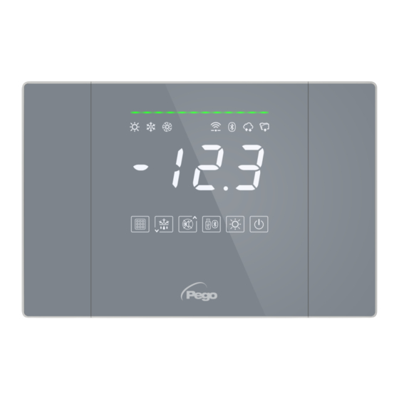
NECTORS27 DATA PROGRAMMING DISPLAY DESCRIPTION ◆ ◆ SYSTEM STATUS LINE The colour indicates a particular state of the system. OFF: system in standby GREEN: system active, no call. BLUE: system active, call cold. -
Page 16: Front Keyboard
Fixed on: Remote device connected via bluetooth. Flashing: Waiting for connection from remote devices. CLOUD CONNECTION ICON Fixed on: device connected to Pego Cloud. DATALOGGER ICON Fixed on: active datalogger (recordings on internal memory, int other than 0). -
Page 17: Key Combinations
NECTORS27 KEY COMBINATIONS EDIT SETPOINT / PARAMETERS Pressing SET (1) and () or () increases or decreases the value of the setpoint or parameter currently displayed. SAVING DATA ON USB STICK If pressed for 5 seconds, internal memory data saving to USB memory is enabled. -
Page 18: General Information
NECTORS27 GENERAL INFORMATION For reasons of safety and greater practicality for the operator, the NECTOR system provides three levels of parameter programming; the first for the configuration of parameters that can be frequently modified by the user, the second reserved for the installer for programming of the parameters relating to the various operating modes and the third reserved for the installer dedicated to the configuration of the system. - Page 19 NECTORS27 1st LEVEL PARAMETERS LIST (User level) PAR. MEANING VALUES DEFAULT Temperature differential referring to the main SET-POINT. 0.2 ÷ 10.0°C 2.0°C 0 ÷ 24 hours Defrost interval (hours) 0 = disabled Delay to start defrosting on the second evaporator. Defrosting of the second evaporator starts dd2 seconds after the end of defrosting 1.
- Page 20 NECTORS27 2nd LEVEL PROGRAMMING (Installer level) To access the second programming level press and hold the UP (), DOWN () and LIGHT keys for a few seconds. When the first programming parameter appears, the system automatically switches to standby. 1. Select with the () key or the () key the parameter to be modified. After selecting it you will be able to: - Display the setting by pressing the SET key.
- Page 21 NECTORS27 PAR. MEANING VALUES DEFAULT 0 = always enabled. 1 = disabled in case of standby. Temperature alarm enabling 2 = disabled if door switch active. 3 = disabled if standby or door switch active. Minimum time between shutdown and next 0 ÷...
- Page 22 NECTORS27 PAR. MEANING VALUES DEFAULT Cold water temperature set point. -45,0 ÷ +99,0 °C 3,0°C Cold water temperature differential. 0,1 ÷ 20,0 °C 5°C Response delay: It’s the time that the analog output 1 ÷ 10 min 10 min takes to vary from 0V to 10V. Evaporator fan speed, only if Ao1=1 20 ÷...
- Page 23 NECTORS27 3rd LEVEL PROGRAMMING (system configurations) 5.11 To access the third programming level press and hold the UP () and STANDBY keys for a few seconds. When the first programming parameter appears, the system automatically switches to standby. 1. Select with the () key or the () key the parameter to be modified. After selecting it you will be able to: - Display the setting by pressing the SET key.
- Page 24 NECTORS27 PAR. MEANING VALUES DEF. 0 = disabled Buzzer enabling 1 = enabled Presence of evaporator probe 1: excluding the evaporator probe, defrosting occurs cyclically with 0 = Disabled period d0 and ends with the intervention of an 1 = Evaporator probe 1 external device that closes the remote defrosting contact or with the expiry of time d31.
- Page 25 NECTORS27 PAR. MEANING VALUES DEF. INP-4 digital input setting - Same legend as in1 values - (terminals 15-16) INP-5 digital input setting - Same legend as in1 values - (terminals 17-18) INP-6 digital input setting - Same legend as in1 values - (terminals 19-20) INP-7 digital input setting - Same legend as in1 values -...
- Page 26 NECTORS27 PAR. MEANING VALUES DEF. Password. 0...999 (see P1 for type of protection). 0 = Function disabled Enabling automatic reconnection 0 … 24 hours If crE>0, the Nector is periodically reconnected to the web/cloud/bluetooth every crE hours, 0 = Function disabled resolving any network errors.
-
Page 27: Data Logging
NECTORS27 DATA LOGGING 5.15 To start recordings set int > 0 Recordings occur in the intervals established by the int parameter, or in case of events if ASr = 1. The information recorded is: • Ambient temperature (IN_1) • Evaporator temperature (IN_2) •... - Page 28 NECTORS27 Confirm the save with the key 5. Wait: at the end of the saving, a short beep is emitted. 6. If an error related to the USB memory occurs, a long beep sounds and Eu flashes with one of the following error codes: 1 –...
- Page 29 NECTORS27 Example of a table obtained by exporting data from NECTOR (CSV) The table in the example shows a number of asynchronous recordings due to an alarm event on channel 1 (ASr = 1). COLUMN DESCRIPTION DATES: Date of recording TIME: Time of recording PROBE1 (0.1°C): Ambient probe temperature (IN_1) PROBE2 (0.1°C): Evaporator probe temperature (IN_2)
-
Page 30: Software Update
To update or update the software it’s necessary to: 1. Download the latest version available from www.pego.it, verify that the release is higher than the one already present in the NECTOR (rEL parameter). 2. Insert the USB stick into the slot on the front panel. -
Page 31: Turning On The Controller
NECTORS27 3. Press the SET key to confirm. The NECTOR controller automatically exports / imports the set parameters and device status. Note: the generated file (name: NECT_200.PAR) can be imported to other NECTOR panels to obtain an identically configured tool. TURNING ON THE CONTROLLER 5.19 After completing complete wiring of the electronic controller, apply 230Vac voltage;... -
Page 32: Evaporators Configuration
NECTORS27 HOT mode (mod parameter = 1) The NECTOR controller activates the heating element command when the room temperature drops below the set value minus the differential (r0); it switches off the resistance when the room temperature is higher than the set value. With mod = 1 it’s possible to connect the heating resistances also to the compressor output (which bears resistive loads greater than the configurable outputs, see chap. -
Page 33: Hot Gas Defrosting
NECTORS27 HOT GAS DEFROSTING 5.23 Parameters: d1 (3°). Set parameter d1 =1 for hot gas defrost management. The compressor relay and defrost relays are activated throughout the defrost phase. For the correct management of the system: - Connect the cycle reversal solenoid valve to the defrost output. - Connect the liquid solenoid valve to the liquid solenoid valve outlet (AUx = +/- 8) Doing so during the defrosting phase will ensure closing of the liquid solenoid valve and activation of the hot gas defrosting cycle. -
Page 34: Password Protection
NECTORS27 PASSWORD PROTECTION 5.28 Parameters: PA (2°), P1 (2°). The password function is activated by setting a value other than 0 for the PA parameter. See parameter P1 for different security levels. Protection is automatically enabled after about 2 minutes of inactivity on the keyboard. ... -
Page 35: Fan Speed Management - 0-10V Output
NECTORS27 FAN SPEED MANAGEMENT – 0-10V OUTPUT 5.31 Parameters: Ao1 (3°), An5 (3°), Au1/2 (3°), FsE (2°). CONDENSER FAN MANAGEMENT If Ao1=2, An5=3 and AU1/2 = +/- 9 the condenser fans are managed with the 0-10V output and sideband type adjustment. The configured auxiliary digital output (AU1 or AU2) is used as consent. The fan speed adjustment follows the operation of graph no. - Page 36 NECTORS27 PRESSURE DECREASING (Graph 2): With pressure values of the pressure probe equal to or greater than point (D) the analog output will be 10V. Between point (D) and point (E) the analogue output will have a value proportional to the value of the pressure probe starting from the maximum value of 10V and reaching the minimum value iMv.
- Page 37 NECTORS27 COLD WATER MANAGEMENT 5.32 Cold water management can be enabled via parameter Ao1. The reference probes change based on the value of An4. Cold water management Ao1=3 An4≠3 An4=3 Reference setpoint Ambient Set Differential Delay in response - Set An4 = 3, if the system directly regulates the temperature of the cold water (with a probe on the pipe) to control the temperature of the air leaving the exchanger.
-
Page 38: Cold Room Door Switch Management
NECTORS27 COLD ROOM DOOR SWITCH MANAGEMENT 5.33 Parameters: doC (2°), Tdo (2°). When the cold room door is opened, the evaporator fans turn off and the compressor will continue to operate for the doC time, after which it will turn off. After the tdo time, normal operation of the control is restored by giving the “open door”... -
Page 39: Valve Control Management
NECTORS27 VALVE CONTROL MANAGEMENT 5.35 To access the valve control management menu, you need to: 1. Press and hold the buttons simultaneously for a few seconds until the first valve control parameter appears on the display. 2. Release the keys. 3. - Page 40 NECTORS27 PAR. MEANING VALUES DEF. Percentage of opening of the EEV valve in case of S4 or S5 probe error. This function allows you 0 ÷ 100% to continue regulation even if not optimally in the event of a failure of the regulation probes. During the Start phase, the EEV valve opens at 0 ÷...
- Page 41 NECTORS27 PAR. MEANING VALUES DEF. MOP Protection (active with tS5>MOP). When the evaporation temperature (tS5) is higher than the MOP threshold, the control stops superheat regulation and the valve closes trying to limit the evaporation temperature (and therefore the pressure). The valve closing speed depends 0 ÷...
- Page 42 NECTORS27 PAR. MEANING VALUES DEF. 3 = tPF % fixed opening (N.O.) 2 = Defrosting (with DI=1) 1 = ON Driver EEV (with DI=1) Setting of digital input DI1 and its activation 0 = Disabled status. -1 = ON Driver EEV (with DI=0) -2 = Defrosting (with DI=0) -3 = tPF % fixed opening (N.C.) Reserved parameter...
- Page 43 NECTORS27 PAR. MEANING VALUES DEF. Rated current per phase (bipolar valves) This is the current per phase used by the valve during regulation. ICM+1 ÷ 800 mA Consult the manufacturer's manual. Stationary current (bipolar valves). It’s the current per phase 0 ÷...
-
Page 44: Loading Default Values Based On Eev Parameter
EEV = 3 EEV = 4 EEV = 5 EEV = 1 (ROOM or TN (ROOM or BT (ROOM or DUCTED (ROOM or DUCTED PEGO REFRIGERATED REFRIGERATED TN REFRIGERATED BT REFRIGERATED DEFAULT COUNTER control with COUNTER control with COUNTER control) -
Page 45: Positioning Of Valve Control Probes
NECTORS27 POSITIONING OF VALVE CONTROL PROBES 5.35.4 Evaporator Condenser Suction Temperature Evaporation Pressure Compressor OPERATION AND MAINTENANCE MANUAL Page 45 Rev. 02-24... -
Page 46: Connection Configuration
NECTORS27 MONITORING CONNECTION CONFIGURATION The NECTOR controller is equipped with Bluetooth BLE, or Ethernet connectivity for Wi-Fi management or monitoring via remote devices (tablets, smartphones, PCs). Remote management of the device takes place in the following ways: Distance Support Channel Mode MyPego app approx. - Page 47 NECTORS27 In the selection bar below, tap the “Cloud” icon to access the network configuration menu. Upon first sign in, the myPego app prompts setting up of your Cloud connection. If relevant, continue by pressing the “Ok” key otherwise press “Cancel” and skip directly to step 14).
- Page 48 NECTORS27 Once the user has been created (or logged in with an existing user), the device must be associated with an existing Cloud subscription; or create a new subscription. Touch the second link to associate the device with the registered user's cloud subscription. If the user does not have an active cloud subscription, the subscription activation page opens.
- Page 49 If the Cloud connection was configured (see points 6 and 7) after a few moments the icon is activated to signal that the device is correctly sending the data to the Pego Cloud. OPERATION AND MAINTENANCE MANUAL Page 49 Rev.
- Page 50 NECTORS27 MyPego APP The myPego app is the official Pego application for the control and supervision of NECTOR line tools. Direct connection to the device via Bluetooth BLE; monitoring system status; changing parameters configuring Ethernet Wi-Fi connectivity. Cloud connection: monitoring of the status of all devices registered in the subscription plan;...
- Page 51 NECTORS27 Connecting to Cloud Device Choosing the Cloud Connection accesses the tool selection page. Here it’s possible to select which of the registered instruments (through the procedure indicated in the previous chapter) it’s possible to access to monitor the status of the system. icon indicates that the tool is successfully transmitting data to the cloud.
- Page 52 NECTORS27 Downloading data: - History Page tap to download data in csv table format Displayed date: Tap to change the date Graph: Tap to view the individual points Legend: Touch the name of a probe to exclude or display it on the chart Table: here it’s possible to read the status of the probes and of any temperature alarms (red for High...
- Page 53 NECTORS27 Device sharing The "Device sharing" function allows you to share the Nector with other users (up to 3) even if they are not subscribers (it’s sufficient that each user has his own account). Users of device sharing: receive alarms and notifications. can check the status of the Nector device.
-
Page 54: Web Server
= active registrations For further information, refer to the dedicated manual HTTP_NECTOR200_XX-YY_ENG.pdf (ask Pego for any updated versions of the document). WEBSERVER Then type the local IP address of the connected tool in the web browser address bar: the login page appears. - Page 55 NECTORS27 WEB INTERFACE: PAGES The Web interface consists of some fixed sections: ▪ left: page navigation menu. ▪ top: Name of the page, serial number and type of user logged on. ▪ on the right: page content. - Home Page Page Navigation Current page Current temperature...
- Page 56 NECTORS27 - I/O (Inputs / Outputs) Input/Output Input/Output Description Input / Output Status Terminal PIN (digital or analogue) If digital: - green: active input / output - grey: input / output not active If analog the analog input or output value is displayed OPERATION AND MAINTENANCE MANUAL Page 56...
- Page 57 NECTORS27 Datalogger => Table On the “Datalogger => Table” page it’s possible to view and print the daily data recorded in the NECTOR memory. To view the records, select a date from the calendar (click on the "Select a date” field) and click on the "Upload” button. Print table (on printer or pdf) High alarm...
- Page 58 NECTORS27 - Datalogger => Graph On the "Datalogger => Graph” page it’s possible to view and print the graph of the daily data recorded in the NECTOR memory. To view the chart, select a date from the calendar (click on the "Select a date” field) and click on the "Upload” button. Legend Print chart By clicking on the entries, it’s possible...
- Page 59 NECTORS27 - Commands => Parameters Parameter menu Click on the arrow to view the parameter list Increases decreases Parameter code Parameter description Current value value OPERATION AND MAINTENANCE MANUAL Page 59 Rev. 02-24...
- Page 60 NECTORS27 - Setup On the "Setup” page it’s possible to configure the language of the webserver. - Info OPERATION AND MAINTENANCE MANUAL Page 60 Rev. 02-24...
-
Page 61: Telenet Monitoring/Supervision System
NECTORS27 TELENET MONITORING/SUPERVISION SYSTEM To connect the NECTOR to the TeleNET monitoring and supervision system perform the following steps: 1. Assign a unique network address using the 3rd level parameter Ad and set Ser=0. 2. The terminals of the TeleNET connection are indicated with RS-485(A) and RS-485(B) on the NECTOR board. - Page 62 NECTORS27 DIAGNOSTICS In the event of any anomalies, the NECTOR system warns the operator through alarm codes, visual and acoustic signalling. When an alarm condition occurs, the red alarm bar is activated, the alarm relay and the buzzer are activated. it’s possible to silence the internal buzzer.
- Page 63 NECTORS27 ALARM POSSIBLE CAUSE OPERATION TO BE PERFORMED CODE • Check the compressor status. Datalogger maximum temperature alarm. • The probe does not detect the temperature The datalogger probe has reached a temperature correctly or the compressor stop/run command higher than that set for the maximum temperature does not work.
- Page 64 NECTORS27 VALVE CONTROL ALARM LIST The following are the integrated valve control alarm codes in order of priority: ALARM POSSIBLE CAUSE OPERATION TO BE PERFORMED CODE • Check the status of the probe and its connections. Functional anomaly of the suction •...
-
Page 65: Maintenance
1) Turn the main switch of the NECTOR to OFF to lock it in this position using a mechanical lock (Pego ACC5ST3801 accessory). 2) Disconnect the power supply upstream of our panel permanently by padlocking it to OFF. -
Page 66: Periodic Verification
ACCREDIA tested and certified. VERIFICATION RESULTS. The Datalogger contained in the NECTOR series panels has a precision class of 1 so: • If the difference between the value measured by the Datalogger and the reference value is between ±1°C, the verification is POSITIVE. -
Page 67: Spare Parts And Accessories
NECTORS27 SPARE PARTS AND ACCESSORIES Spare parts and accessories for the NECTOR panel: • SON103C4R1L1500 - NTC probe 10K 1% black 1.5m in length. • SON103C4R1L3000 - NTC probe 10K 1% black 3m in length. • SONNTC3MCE - NTC 10K 1% yellow probe of 3m length. •... -
Page 68: Eu Declaration Of Conformity
THIS DECLARATION OF CONFORMITY IS ISSUED UNDER THE EXCLUSIVE RESPONSIBILITY OF THE MANUFACTURER: PEGO S.r.l. Via Piacentina 6/b, 45030 Occhiobello (RO) – Italy – Società soggetta all’attività di direzione e coordinamento di Castel S.r.l. DENOMINAZIONE DEL PRODOTTO IN OGGETTO / DENOMINATION OF THE PRODUCT IN OBJECT MOD.:... - Page 69 NECTORS27 NECTOR200S27 CONNECTION DIAGRAM OPERATION AND MAINTENANCE MANUAL Page 69 Rev. 02-24...
- Page 70 NECTORS27 VALVE CONTROL CONNECTION DIAGRAM (NECTORS27) Terminal No. Description 30-31 24Vdc power supply 32-33-34-35 Stepper Valve 43-44 tS4 NTC suction probe 4-20mA - PS5 Evaporation pressure probe 15V - PS5 Evaporation pressure probe EXP_A Connection to Nector EXP_B Connection to Nector OPERATION AND MAINTENANCE MANUAL Page 70 Rev.
- Page 71 NECTORS27 Valve connection based on tEu parameter: Valve (par. tEU) PIN 32 PIN 33 PIN 34 PIN 35 1 = Carel EXV GREEN BROWN YELLOW WHITE 2 = Danfoss ETS 25-50 GREEN WHITE BLACK 3 = Danfoss ETS 100 GREEN WHITE BLACK 4 = Danfoss ETS 250/400...
-
Page 72: Technical Assistance
Tel. +39 0425 762906 e-mail: info@pego.it – www.pego.it TECHNICAL ASSISTANCE Tel. +39 0425 762906 e-mail: tecnico@pego.it Distributor: PEGO s.r.l. reserves the right to make changes to this user manual at any time. OPERATION AND MAINTENANCE MANUAL Page 72 Rev. 02-24...
Need help?
Do you have a question about the NECTOR Series and is the answer not in the manual?
Questions and answers