
Related Manuals for Pego NECTOR


Summary of Contents for Pego NECTOR
- Page 1 NECTOR Operation and maintenance manual READ AND KEEP REV. 03-21 ELECTRICAL BOARDS FOR REFRIGERATING INSTALLATIONS OPERATION AND MAINTENANCE MANUAL Page 1 Rev. 03-21...
- Page 2 NECTOR OPERATION AND MAINTENANCE MANUAL Page 2 Rev. 03-21...
- Page 3 Thank you for choosing a PEGO electrical panel. This manual provides detailed information on the installation, use and maintenance of the NECTOR series electrical panels. Our products are designed and manufactured in compliance with current safety standards, in the specific field of use of refrigeration and air conditioning systems.
-
Page 4: Table Of Contents
INSTALLATION Page 9 Warnings for the installer Page 9 Pack contents Page 10 Panel installation FUNCTIONALITY Page 12 Functions managed by NECTOR TECHNICAL SPECIFICATIONS Page 14 Technical specifications Page 15 Warranty conditions DATA PROGRAMMING Page 16 Display description Page 17... - Page 5 NECTOR MONITORING Page 40 Connections configuration Page 43 myPego App Page 46 Integrated webserver / http Access Page 53 Telenet monitoring / supervision system Page 53 Modbus-RTU Protocol DIAGNOSTICS Page 54 Diagnostics MAINTENANCE Page 57 General safety rules Page 58...
-
Page 6: Introduction
GENERAL INFORMATION DESCRIPTION: NECTOR is a control panel for refrigerated cells with a single-phase compressor up to 2HP that integrates the Datalogger function and various connectivity functions. It complies with Regulation (EC) 37/2005 and with the relative standard EN 12830, with Directives 89/108/EEC, 92/2/EEC and with Italian Legislative Decrees no. - Page 7 - RS485 for connection to the TeleNET or ModBUS supervision network - TeleNET program downloadable free of charge from the website www.pego.it for the storage and consultation of data downloaded with the USB memory from the NECTOR panels. OPERATION AND MAINTENANCE MANUAL Page 7 Rev.
-
Page 8: Product Identification Codes
NECTOR PRODUCT IDENTIFICATION CODES NECTOR200 Cell control management with single-phase compressor up to 2HP static or ventilated and Datalogger function (up to 2 years of recording). USB slot for downloading data. General protection differential circuit breaker 16A curve C, Id=300mA. -
Page 9: Installation
ACCREDIA tested and certified. PACK CONTENTS The NECTOR electronic controller, for assembly and use, is equipped with: • No. 3 Seals, to be interposed between the fixing screw and the bottom of the box. • No. 1 User manual. -
Page 10: Panel Installation
NECTOR PANEL INSTALLATION Fig. 1: Press the buttons on the side doors to release them from the locked position. Fig. 2: Lift the two side doors and loosen the four screws that secure the front to the base. Fig. 3: Open the front of the box by lifting it and sliding the two hinges to the end of the stroke. - Page 11 On all loads connected to the NECTOR electronic controller, install overcurrent protection devices for short circuits, in order to avoid damage to the device. Every intervention and/or maintenance operation must be carried out by disconnecting the panel from the power supply and from all possible inductive and power loads to which it is connected;...
-
Page 12: Functionality
NECTOR FUNCTIONALITY FUNCTIONS MANAGED BY NECTOR Direct compressor management, defrosting resistors, evaporator fans, cell light. Display and adjustment of the cell temperature with decimal point. Humidification function with dedicated 4-20mA humidity probe. Probe display menu (Ambient temperature probe, evaporator temperature probe, Datalogger temperature probe, second evaporator temperature probe or product temperature probe, humidity probe or pressure probe). - Page 13 NECTOR USB software function update. Parameter import / export function via USB. General protection differential circuit breaker 16A curve C Id=300mA. Backup battery that keeps real-time temperature recordings active in the absence of the main power supply (if present). Wi-Fi, Ethernet and Bluetooth (BLE) connectivity.
-
Page 14: Technical Specifications
NECTOR TECHNICAL SPECIFICATIONS TECHNICAL SPECIFICATIONS Power supply Voltage 85 - 260 V~ (± 10%) Frequency 50-60Hz Max. power consumption (electronic controls only) 10 W Climatic conditions Working temperature 0T50°C Storage temperature -20T60°C Relative ambient humidity (non-condensing) Less than 90% Hr... -
Page 15: Warranty Conditions
Pego S.r.l. declines all responsibility for the possible inaccuracies contained in this manual, if due to printing or transcription errors. Pego S.r.l. reserves the right to make any changes to its products that it deems necessary or useful, without affecting their essential characteristics. -
Page 16: Data Programming
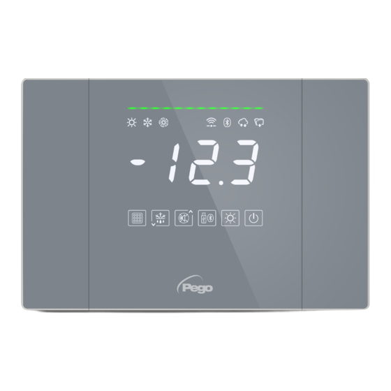
NECTOR DATA PROGRAMMING DISPLAY DESCRIPTION ◆ ◆ SYSTEM STATUS LINE The colour indicates a particular state of the system. OFF: system in standby GREEN: system active, no call. -
Page 17: Front Keyboard
Fixed on: Remote device connected via bluetooth. Flashing: Waiting for connection from remote devices. CLOUD CONNECTION ICON Fixed on: device connected to Pego Cloud. DATALOGGER ICON Fixed on: active datalogger (recordings on internal memory, int other than 0). -
Page 18: Key Combinations
NECTOR KEY COMBINATIONS EDIT SETPOINT / PARAMETERS Pressing SET (1) and ( ) or ( ) increases or decreases the value of the setpoint or parameter currently displayed. SAVING DATA ON USB STICK If pressed for 5 seconds, internal memory data saving to USB ... -
Page 19: General Information
NECTOR GENERAL INFORMATION For reasons of safety and greater practicality for the operator, the NECTOR system provides three levels of parameter programming; the first for the configuration of parameters that can be frequently modified by the user, the second reserved for the installer for programming of the parameters relating to the various operating modes and the third reserved for the installer dedicated to the configuration of the system. - Page 20 NECTOR 1st LEVEL OF PROGRAMMING (User level) To access the first level configuration menu you must: 1. Press and hold the () and () keys simultaneously for a few seconds until the first programming variable appears on the display. 2. Release the () and () keys.
- Page 21 NECTOR Dripping duration (minutes) 0 ÷ 10 min At the end of defrosting, the compressor and fans remain 0 min stationary for the set time d7, the defrosting LED on the front 0 = disabled of the panel flashes. Fan pause after defrosting (minutes).
- Page 22 NECTOR 2nd LEVEL OF PROGRAMMING (Installer level) To access the second programming level press and hold the UP (), DOWN () and LIGHT keys for a few seconds. When the first programming variable appears, the system automatically switches to standby.
- Page 23 NECTOR 0 = always enabled 1 = disabled in case of standby Temperature alarm enabling 2 = disabled if door switch active 3 = disabled if standby or door switch active Minimum time between shutdown next 0 ÷ 15 minutes 0 min compressor power on.
- Page 24 NECTOR Condenser fan pressure set -0.5 ÷ 90.0 Bar Differential condenser fan pressure SET. Value 2.0 Bar 5.0 Bar always above the value of (iOv) 2.5 bar Fan inverter offset (pressure) 0.5 Bar always < r2 Fan inverter: setting the minimum value of the ...
-
Page 25: List Of Third Level Variables
NECTOR 3rd LEVEL OF PROGRAMMING (system configurations) 5.11 To access the third programming level press and hold the UP () and STANDBY keys for a few seconds. When the first programming variable appears, the system automatically switches to standby. 1. Select with the () key or the () key the variable to be modified. After selecting the desired variable you will be able to: - Display the setting by pressing the SET key. - Page 26 NECTOR Presence of evaporator probe 1: excluding evaporator probe, defrosting occurs cyclically with period d0 and ends with the 0 = disabled intervention of an external device that closes 1 = Evaporator probe 1 the remote defrosting contact or with the expiry of time d31.
- Page 27 NECTOR INP-6 digital input setting - Same legend in1 values - INP-7 digital input setting - Same legend in1 values - 11 = defrost output 2 (N.O.) 10 = active night mode (N.O.) 9 = condenser fan consent (N.O., managed if An5=2, high pressure probe) 8 = liquid solenoid (N.O., for hot gas defrosting...
-
Page 28: Probe Display (Read-Only)
NECTOR Setting the default parameters Assume a position on the dEF parameter and - - - - - - press the + keys for 10 seconds reset the default parameters. PROBE DISPLAY ( read-only) 5.13 To access the probe display level press and hold the DOWN () and STANDBY keys for a few seconds. -
Page 29: Data Logging
Through the TeleNET program it is possible to store, consult, view graphs and to print quickly and easily the data downloaded from the NECTOR panels. Alternatively, it is possible to download all the data stored in the NECTOR EXPERT in standard comma-separated values (CSV) format that can be viewed on PC with any spreadsheet. - Page 30 NECTOR - pg3: Export data in secure format compatible with the TeleNET supervision software. - CSv: Export data in standard table text format. Confirm the save with the key 5. Wait: a short beep will sound when the save is complete.
- Page 31 NECTOR TeleNET - Example of graph obtained by importing data from NECTOR (PG3) Example of a table obtained by exporting data from NECTOR (CSV) The table in the example shows a number of asynchronous recordings due to an alarm event on channel 1 (ASr = 1).
- Page 32 An5=1/2: humidity probe enabled on PROBE5 (IN_12) An5=3: pressure probe enabled on PROBE5 (IN_12) POWER-ON: start of the NECTOR (recording performed asynchronously, regardless of the parameter 'int’: in this way it is possible to understand when the power returns). DI1: Digital input DI1 active (IN_5)
-
Page 33: Software Update
PARAMETER EXPORT/IMPORT 5.18 The parameters set in the NECTOR can be exported/imported via the USB port used to download the data. To do this, proceed as follows: 1. Insert the USB stick into the slot on the front panel. -
Page 34: Evaporator Configuration
HOT mode (mOd parameter=1) The NECTOR controller activates the hot resistance control when the ambient temperature drops below the set value minus the differential (r0); it switches off the resistance when the ambient temperature is higher than the set value. -
Page 35: Changing Of Date And Time Settings
NECTOR For the correct management of the system: - Connect the cycle reversal solenoid valve to the defrost output. - Connect the liquid solenoid valve to the liquid solenoid valve outlet (AUx = +/- 8) Doing so during the defrosting phase will ensure closing of the liquid solenoid valve and activation of the hot gas defrosting cycle. -
Page 36: Password Protection
NECTOR PASSWORD PROTECTION 5.28 Parameters: PA (2°), P1 (2°). The password function is activated by setting a value other than 0 for the PA parameter. See parameter P1 for different security levels. Protection is automatically enabled after about 2 minutes of inactivity on the keyboard. -
Page 37: Fan Speed Management - 0-10V Output
NECTOR FAN SPEED MANAGEMENT - 0-10V OUTPUT 5.31 Parameters: Ao1 (3°), An5 (3°), Au1/2 (3°), FsE (2°). CONDENSER FAN MANAGEMENT If Ao1=2, An5=3 and AU1/2 = +/- 9 the condenser fans are managed with the 0-10V output and sideband type adjustment. The configured auxiliary digital output (AU1 or AU2) is used as consent. - Page 38 NECTOR PRESSURE DECREASING (Graph 2): With pressure values of the pressure probe equal to or greater than point (D) the analog output will be 10V. Between point (D) and point (E) the analogue output will have a value proportional to the value of the pressure probe starting from the maximum value of 10V and reaching the minimum value iMv.
-
Page 39: Humidification Management
5.33 Parameters: Au1/2 (3°), StU (2°), r1 (2°). The NECTOR controller activates the humidity call when the ambient humidity drops below the set value StU minus the differential r1; it disengages the humidity call when the ambient humidity exceeds the set value. Configure Au1/2 = +/- 7 to enable a digital output as humidification consent. -
Page 40: Monitoring
The myPego app is available on Google and Apple stores for free. It allows complete control of the NECTOR tool and is necessary to perform the basic operations to connect the device to the Internet (check IP address, enter Wi-Fiusername and password, etc. - Page 41 NECTOR The Homepage of the application opens, where it is possible to see the cell temperature and to check the status of inputs and outputs. In the selection bar below, tap the “Cloud” icon to access the network configuration menu.
- Page 42 IP received from the DHCP server. In the case of wi-fi connection, touch the WI-FI ON switch and configure the SSID and password of the network to which the NECTOR is to connect. At the end of the setting touch the "Send settings" button.
-
Page 43: Mypego App
NECTOR MyPego APP The myPego app is the official Pego application for the control and supervision of NECTOR line tools. Direct connection to the device via Bluetooth BLE; monitoring system status; changing parameters configuring Ethernet wi-fi connectivity. Cloud connection: monitoring of the status of all devices registered in the subscription plan;... - Page 44 NECTOR instrument status Once logged in (via Bluetooth if it is a nearby instrument or via Cloud if it is a remote instrument) the NECTOR status page opens. Here it is possible to: - Read current ambient temperatures. - Read the setpoint and modify it (if connected via Bluetooth).
- Page 45 NECTOR Downloading data: - History Page tap to download data in csv table format Displayed date: Tap to change the date Graph: Tap to view the individual points Legend: Touch the name of a probe to exclude or display it...
-
Page 46: Integrated Webserver / Http Access
Access to the NECTOR homepage is subject to access control by Username and password. The NECTOR Web pages can be accessed in two modes, depending on the value of the cSL parameter (3rd parameter level): - If cSL=1, Normal user: entering in the “Username” field the string “admin” and in the "Password”... - Page 47 NECTOR WEB INTERFACE: PAGES The Web interface consists of a number of fixed sections: ▪ left: page navigation menu. ▪ top: Name of the page, serial number and type of user logged on. ▪ on the right: page content. - Home Page...
- Page 48 NECTOR - I/O (Inputs / Outputs) Input/Output Input/Output Description Input / Output Status Terminal PIN (digital or analogue) If digital: - green: active input / output - grey: input / output not active If analog the analog input or output...
- Page 49 On the “Datalogger => Table” page it is possible to view and print the daily data recorded in the NECTOR memory. To view the records, select a date from the calendar (click on the "Select a date” field) and click on the "Upload” button.
- Page 50 On the "Datalogger => Graph” page it is possible to view and print the graph of the daily data recorded in the NECTOR memory. To view the chart, select a date from the calendar (click on the "Select a date” field) and click on the "Upload” button.
- Page 51 NECTOR - Commands => Parameters Parameter menu Click on the arrow to view the parameter list Increases decreases Parameter code Parameter description Current value value OPERATION AND MAINTENANCE MANUAL Page 51 Rev. 03-21...
- Page 52 NECTOR - Setup On the "Setup” page it is possible to configure the language of the webserver. - Info OPERATION AND MAINTENANCE MANUAL Page 52 Rev. 03-21...
-
Page 53: Telenet Monitoring/Supervision System
NECTOR TELENET MONITORING/SUPERVISION SYSTEM To connect the NECTOR to the TeleNET monitoring and supervision system perform the following steps: 1. Assign a unique network address using the 3rd level variable Ad, and set Ser=0. 2. The terminals of the TeleNET connection are indicated with RS-485(A) and RS-485(B) on the NECTOR board. -
Page 54: Diagnostics
NECTOR DIAGNOSTICS DIAGNOSTICS In the event of any anomalies, the NECTOR system warns the operator through alarm codes, visual and acoustic signalling. When an alarm condition occurs, the red alarm bar is activated, the alarm relay and the buzzer are activated. - Page 55 NECTOR Man in cold room alarm. • Check the hazardous situation and reset the The “man in cold room alarm” button inside the cell button inside the cell. has been pressed to signal a dangerous situation. • Check that the door is closed.
- Page 56 NECTOR • Check the compressor status. • Check the compressor protection oil pressure Compressor oil pressure switch protection insertion: (the outputs are all deactivated except switch. • If the problem persists, contact technical for the alarm one, if present). support.
-
Page 57: Maintenance
Permanently and safely disconnect the power supply to the panel in one of the ❑ following ways: 1) Turn the main switch of the NECTOR to OFF to lock it in this position using a mechanical lock (Pego ACC5ST3801 accessory). 2) Disconnect the power supply upstream of our panel permanently by padlocking it to OFF. -
Page 58: Periodic Verification
NECTOR PERIODIC VERIFICATION The NECTOR is tested and adjusted at the factory as attested by the "calibration report" included in this package. When it is in service, its periodic verification is necessary to ensure the reliability of the records as established by UNI EN12830 and in accordance with UNI EN13486. -
Page 59: Spare Parts And Accessories
For external cleaning of the panel, use only a damp cloth with a small quantity of neutral detergent. DISPOSAL The NECTOR panel consists of plastic, cables, printed circuit board and electronic components. With reference to Directive 2012/19/EU of the European Parliament and of the Council of 4 July 2012 and the relevant national legislation on the subject, we inform you that: A. -
Page 60: Eu Declaration Of Conformity
THIS DECLARATION OF CONFORMITY IS ISSUED UNDER THE EXCLUSIVE RESPONSIBILITY OF THE MANUFACTURER: PEGO S.R.L. Via Piacentina 6/b, 45030 Occhiobello (RO) – Italy – Società soggetta all’attività di direzione e coordinamento di Castel S.r.l. DENOMINAZIONE DEL PRODOTTO IN OGGETTO / NAME OF THE PRODUCT IN QUESTION... -
Page 61: Nector200 Connection Diagram
NECTOR NECTOR200 CONNECTION DIAGRAM INPUTS OUTPUTS OPERATION AND MAINTENANCE MANUAL Page 61 Rev. 03-21... - Page 62 NECTOR OPERATION AND MAINTENANCE MANUAL Page 62 Rev. 03-21...
- Page 63 NECTOR OPERATION AND MAINTENANCE MANUAL Page 63 Rev. 03-21...
- Page 64 Tel. +39 0425 762906 e-mail: info@pego.it – www.pego.it AFTER SALES SERVICE Tel. +39 0425 762906 e-mail: tecnico@pego.it Agency: PEGO s.r.l. reserves the right to make changes to this user manual at any time. OPERATION AND MAINTENANCE MANUAL Page 64 Rev. 03-21...
Need help?
Do you have a question about the NECTOR and is the answer not in the manual?
Questions and answers
Where do i connect product probe on this nector