Advertisement
Quick Links
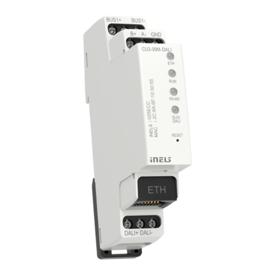
CU3-09M/DALI
Central unit with 1x BUS, 1x DALI
EN
EN
Characteristics
• CU3-09M is one of the basic system control units of iNELS BUS istallations.
• The unit can work independently, as an autonomous project, or it can be contro-
lled by the central software as part of a larger project.
• The unit is equipped with one BUS to swich it is possible to connect up to 32 ele-
ments from the iNELS BUS portfolio.
• The current load of one line is max. 1 A. BPS3-01M with 3 A can be used incase of
connected device with more than 1 A.
• The CU3-09M/DALI system unit is equipped with one DALI bus.
• The DALI system bus allow control of up 64 independent DALI for devices.
• Addressing of DALI can be done via the iDM3 software.
• The RJ45 100 Mbps Ethernet connector is used direct communication with the
cloud for mobile app control or for communication with the superior unit within
the iNELS IP topology.
• Confi guration takes place in the iNELS3 Designer & Manager software (iDM3).
• Through iDM3 it is possible to update the fi rmware of central units and bus co-
nnected peripheral units.
• The central unit is implemented with MQTT protocol for 3rd party communica-
tion.
• The unit is powered by 27 V DC from iNELS power supply.
• System units CU3-09M/DALI in 1-MODULE design are designed for mouting into
a switchboard on DIN rail EN60715.
Connection
1
2
3
4
5
6
7
8
9
1. Power supply terminals
2. DALI interface
3. LED indication of communication Ethernet
4. LED indication of unit operating status
5. DALI bus LED indication
6. BUS bus LED indication
7. Reset button
8. Ethernet port 100 Mbps (RJ45)
9. BUS data bus
Description of device
L
120 - 230V AC
N
Technical parameters
Indication LED STATUS
Green - RUN:
Red - ERR:
Communication
System BUS
Maximum number of units:
Status indication (LED BUS):
Output interface DALI
DALI addresses max.
Bus power supply:
Status indication (LED DALI):
Ethernet
Connector:
Communication speed:
Ethernet status indication
(LED ETH):
Default IP address:
RESET button
Restart:
Reset (return to factory
settings):
Power
Supply voltage/tolerance:
Rated current:
Operating conditions
Working temperature:
Storage temperature:
Air humidity:
Degree of protection:
Degree of pollution:
Working position:
Installation:
Design:
Terminal plate:
Dimensions and weight
Dimensions:
Weight:
Standards:
02-20/2024
+27V
GND
DA DA
ETH
BUS+
The main program runs
The main program stalled
max. 32 Units
green: BUS Operating Status
red: error indication on the bus
64
external DALI power supply must be connected
green: DALI Operating Status
RJ45
100 Mbps
green - Ethernet communication
yellow - speed Ethernet 100 Mbps
192.168.1.1
short press
press the button to bring power on,
button release 10 s after power is supplied
27 V DC, -20/+10 %
50 mA (at 27 V DC)
-20 to +55 °C
-25 to +70 °C
max. 80%
IP20 device, IP40 with cover in the control cabinet
2
any
to the control cabinet for DIN rail EN 60715
1-MODULE
2
max. 2.5 mm
94 x 17.6 x 64 mm
72 g
EN 63044-1, EN 62368-1
DALI
LIGHT
up to 64
DALI
address
BUS-
BUS
+
BUS
–
1/2
Advertisement

Related Manuals for iNels CU3-09M/DALI


Summary of Contents for iNels CU3-09M/DALI
- Page 1 Central unit with 1x BUS, 1x DALI 02-20/2024 Characteristics Description of device • CU3-09M is one of the basic system control units of iNELS BUS istallations. DALI • The unit can work independently, as an autonomous project, or it can be contro- 120 - 230V AC LIGHT lled by the central software as part of a larger project.
- Page 2 ELKO EP, s.r.o. | Palackého 493 | 769 01 Holešov, Všetuly | Czech republic | e-mail: elko@elkoep.com TECHNICAL SUPPORT | E-mail: support@inels.com | Mobil: +420 777 356 466 | Tel.: +420 573 514 276, +420 573 514 211 | Fax: +420 573 514 227 | www.inels.com...
Need help?
Do you have a question about the CU3-09M/DALI and is the answer not in the manual?
Questions and answers