Advertisement
Quick Links
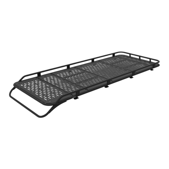
S PRI NTER VAN S AFARI R ACK - 14 4" D RO P FR ON T
SP0107 B
INSTALLATION
GUIDE
F L AT L I N E VA N C O • S U P P O R T @ F L AT L I N EVA N C O . C O M • 8 8 8 - 6 6 7- 5 5 7 6
TOOLS REQUIRED
(NOT INCLUDED)
+
MEASURING TAPE
+
QWICK CLAMPS
+
3/8" WRENCH OR SOCKET
+
7/16" WRENCH OR SOCKET
+
9/16" WRENCH OR SOCKET
+
5/32" ALLEN WRENCH
INSTALL INFO
TIME TO INSTALL THIS PRODUCT: 3-4 HOURS
Additional help is suggested for a few of the install
steps.
BEFORE YOU START
Please inspect the product and packaging upon
delivery to ensure there are no issues and that all
parts and hardware are accounted for.
Contact us ASAP if anything is missing at:
support@flatlinevanco.com
0 1
Advertisement

Related Manuals for FVC SP0107B


Summary of Contents for FVC SP0107B
- Page 1 INSTALLATION GUIDE S PRI NTER VAN S AFARI R ACK - 14 4” D RO P FR ON T SP0107 B TOOLS REQUIRED (NOT INCLUDED) MEASURING TAPE QWICK CLAMPS 3/8” WRENCH OR SOCKET 7/16” WRENCH OR SOCKET 9/16” WRENCH OR SOCKET 5/32”...
- Page 2 BEFORE YOU START All Flatline Van Co products must be properly assembled and secured before attaching to your vehicle. Improper attachment could result in an automobile accident, and could cause serious bodily injury or death to you or to others involved. You are responsible for assembling and securing Flatline Van Co products to your vehicle, checking the mounting points and attachments prior to use, and regularly inspecting the products for wear and or damage.
- Page 3 PACKAGE CONTENTS DROP FRONT SIDE RAIL FRONT BASKET REAR BASKET BAYONET QTY: 6 QTY: 1 QTY: 1 QTY: 1 QTY: 8 FLOOR SECTION FAN SIDE PANEL FLOOR SECTION FAN COVER SAFARI RAIL MOUNT F45 AWNING BRACKET FLOOR SECTION 2 QTY: 8 QTY: 3 QTY: 4 QTY: 2...
- Page 4 HARDWARE 3/8-16 X 0.75 FLANGED HEX 3/8-16 X 1 CARRIAGE BOLT RAIL NUTS 1/4-20 T-NUT 3/8-16 NYLON LOCKNUT HEAD SCREW QTY: 22 QTY: 8 QTY: 43 QTY: 22 QTY: 8 1/4-20 X 0.75 FLANGED HEX 1/4-20 X 0.75 FLANGED BUTTON 1/4-20 X 0.5 FLANGED BUTTON 3/8 SCREW FLAT WASHER 3/8 BELLEVILLE LOCK WASHER...
- Page 5 TOOLS REQUIRED FOR THIS STEP: MEASURING TAPE STEP | 01 LAYOUT AND INSTALL PREP 1.1 Install Rail Nuts: Slide (4) Rail Nuts into the Passenger Side factory roof rail (FIG 1), and (4) into the Driver Side rail. If you purchased a Side Ladder to go with your Safari Rack (FIG 2), add two more to the Driver Side Rail in the location shown in FIG 2+3.
- Page 6 5/32” ALLEN WRENCH TOOLS REQUIRED FOR THIS STEP: 9/16” WRENCH OR SOCKET STEP | 02 SIDE RAIL ASSEMBLY 2.1 Assemble Side Rails: Insert a Bayonet into the end of a Side Rail (FIG 5+6) and use (2) 1/4-20 x 0.75 Flanged Button Head Screws (not the shorter ones) to loosely secure the Bayonet in place.
- Page 7 QWICK CLAMPS TOOLS REQUIRED FOR THIS STEP: 3/8” WRENCH OR SOCKET 7/16” WRENCH OR SOCKET STEP | 02 SIDE RAIL INSTALL 2.4 Fasten Side Rails Together: Secure the connection with a 1/4-20 Flanged Hex Bolt, Washer and Nylon Locknut. Insert the bolt through the smaller hole inside the larger wire pass- through hole (FIG 7).
- Page 8 TOOLS REQUIRED FOR THIS STEP: 9/16” WRENCH OR SOCKET STEP | 03 SIDE RAIL INSTALL 3.1 Mount Side Rails to Van Rails: With assistance, lift the Side Rail Assembly onto the roof (FIG 8). Align the Mounting Feet with the roof Rail Nuts and insert a 3/8-16” Flanged Hex Head Bolt and Belleville Lock Washer into the available mounting hole as shown in FIG 9.
- Page 9 TOOLS REQUIRED FOR THIS STEP: 5/32” ALLEN WRENCH QWICK CLAMPS 3/8” WRENCH OR SOCKET 7/16” WRENCH OR SOCKET STEP | 04 ATTACH BASKETS TO RAILS 4.1 Attach Front and Rear Baskets: With help, carefully attach the Front Basket to the protruding Bayonets and secure the connections using (2) 1/4-20 x 0.75 Flanged Button Head Screws (not the shorter ones) for the Bayonets and a 1/4-20 Flanged Hex Bolt, Washer and Nylon Locknut for the Side Rail...
- Page 10 TOOLS REQUIRED FOR THIS STEP: 3/8” WRENCH OR SOCKET 7/16” WRENCH OR SOCKET STEP | 05 ATTACH DROP FRONT 5.1 Attach Drop Front: The Drop Front mounts to the underside tray of the Front Basket Weldment. You will need to maneuver it around your antenna to get it in place, so having a second person helps immensely for this step.
- Page 11 TOOLS REQUIRED FOR THIS STEP: MEASURING TAPE 9/16” WRENCH OR SOCKET STEP | 06 INSTALL AWNING BRACKETS 6.1 F45 Awning Brackets (optional): If you purchased a Fiamma F45 Awning with your rack, install the (3) Awning Brackets at this time using (2ea) 3/8-16” Carriage Bolts, Flat Washers and Nylon Locknuts.
- Page 12 TOOLS REQUIRED FOR THIS STEP: MEASURING TAPE 7/16” WRENCH OR SOCKET STEP | 07 INSTALL CROSSBARS 7.1 Attach Crossbars: Using (4ea) 1/4-20 Flanged Hex Bolts with Loctite (FIG 14), attach Crossbars to the rack in the locations shown in FIG 18. Be sure to measure on both sides to ensure that the Crossbars are square.
- Page 13 TOOLS REQUIRED FOR THIS STEP: STEP | 08 PREP FOR PANELS 8.1 Attach Clip Nuts to Baskets: Install the Clip Nuts to the Front and Rear Basket locations as shown in FIG 19. NOTE - The flat side of the Clip Nut should be facing upwards (FIG 20) F I G 19 F I G 2 0...
- Page 14 TOOLS REQUIRED FOR THIS STEP: STEP | 08 PREP FOR PANELS 8.2 Layout T-Nuts: Consider the layout plan of your roof accessories and install T-Nuts into the available slots of the Crossbars as shown in FIG 21. See FIG 22 for amounts of T-Nuts needed per slot if using exclusively decking panels.
- Page 15 TOOLS REQUIRED FOR THIS STEP: FLOOR SECTION 6 STEP | 09 INSTALL FLOOR PANELS BACK FLOOR SECTION FAN SIDE PANEL 9.1 Install Floor Panels: Begin to layout your Decking Panels FLOOR SECTION FAN COVER along the locations shown in FIG 23. Adjust the T-Nuts as FLOOR SECTION 4 necessary to line up with the available pill slots of the Decking Panels (FIG 24).
- Page 16 TOOLS REQUIRED FOR THIS STEP: 5/32” ALLEN WRENCH STEP | 09 INSTALL FLOOR PANELS 9.2 Install Floor Panels: Note that the front and rear-most CLIP NUT MOUNT panels have pill slots for attaching to the Clip Nuts installed earlier (FIG 25). Use the 1/4-20 x 0.5” Flanged Button Head Screws for the Decking Panels that attach to Crossbars, and the longer 0.75”...
- Page 17 FVC (and see) from you! Head to the products and following along and we will make it right. FVC is product page and click “Leave a company of van and outdoor with your adventures. Tag us Review.”...
Need help?
Do you have a question about the SP0107B and is the answer not in the manual?
Questions and answers