Siemens SENTRON 7KTPAC1200 System Manual
Multi channel current measuring system
Hide thumbs
Also See for SENTRON 7KTPAC1200:
- System manual (88 pages) ,
- Operating instructions manual (6 pages) ,
- Operating instructions manual (8 pages)

Related Manuals for Siemens SENTRON 7KTPAC1200


Summary of Contents for Siemens SENTRON 7KTPAC1200
- Page 3 Introduction Safety notes Product description Connection Measuring Devices 7KT PAC1200 multichannel Operator control (software) current measuring system Service and maintenance System Manual Technical data Appendix ESD guidelines 10/2024 2514374103_RS-AA_005...
- Page 4 Note the following: WARNING Siemens products may only be used for the applications described in the catalog and in the relevant technical documentation. If products and components from other manufacturers are used, these must be recommended or approved by Siemens. Proper transport, storage, installation, assembly, commissioning, operation and maintenance are required to ensure that the products operate safely and without any problems.
- Page 5 Table of contents Introduction ............................5 Introduction......................... 5 Technical Support ........................ 5 Change documentation ....................... 5 Safety notes ............................7 Safety instructions ....................... 7 Cybersecurity information ....................10 Open Source Software ....................... 10 Product description..........................13 Products of the system ....................... 13 Functions...........................
- Page 6 Table of contents Technical Support ......................45 Cybersecurity........................45 6.3.1 Introduction........................46 6.3.2 Further information on the defense-in-depth strategy............46 6.3.3 Application environment....................46 6.3.4 Firmware update........................ 46 6.3.5 Communication protocols ....................47 6.3.6 Removing the device from service ..................47 6.3.7 Guideline for secure operation and commissioning.............
- Page 7 You can find further details in the following documents: • Operating Instructions 7KT PAC1200 multichannel current measuring system (https:// support.industry.siemens.com/cs/ww/en/view/109483797) Technical Support You can find further support on the Internet at: TechnicalSupport (https://www.siemens.com/support-request) Change documentation Document Revisions identification number 2514374102_RS-...
- Page 8 Introduction 1.3 Change documentation 7KT PAC1200 multichannel current measuring system System Manual, 10/2024, 2514374103_RS-AA_005...
- Page 9 Safety notes Safety instructions The safety instructions that have to be followed when using the 7KT PAC1200 multichannel current measuring system are given below. DANGER Hazardous voltage. Will cause death or serious injury. Turn off and lock out all power supplying this device before working on it. Installation and maintenance work on this device must by carried out by authorized persons with the appropriate electrical training only.
- Page 10 Safety notes 2.1 Safety instructions NOTICE Device can be irreparably damaged When performing an insulation test of the entire installation with AC or DC, disconnect the device before starting the test. NOTICE Damage to, or destruction of, the Data Manager. Material damage. Do not connect an ISDN cable to the Data Manager’s network connection.
- Page 11 For safety reasons, changes to the sensor bar are forbidden unless expressly approved for the product by Siemens AG. Any use of the product other than the intended use described is considered improper use. Impermissible modification, conversions, repairs, or opening of the product are forbidden.
- Page 12 Siemens’ products and solutions undergo continuous development to make them more secure. Siemens strongly recommends that product updates are applied as soon as they are available and that the latest product versions are used. Use of product versions that are no longer supported, and failure to apply the latest updates may increase customer's exposure to cyber threats.
- Page 13 Product or any OSS components contained in it if they are modified or used in any manner not specified by SIEMENS. The license conditions may contain disclaimers that apply between you and the respective licensor.
- Page 14 Safety notes 2.3 Open Source Software 7KT PAC1200 multichannel current measuring system System Manual, 10/2024, 2514374103_RS-AA_005...
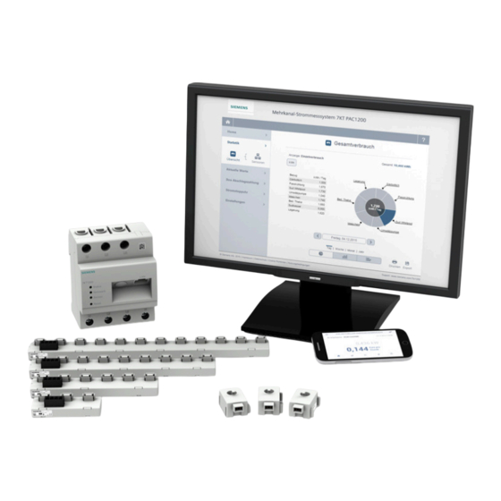
- Page 15 Product description Products of the system ① Mobile terminal device ② Web browser ③ SENTRON Powermanager ④ Router ⑤ Power distribution ⑥ Device for which current is being monitored The 7KT PAC1200 multichannel current measuring system is part of the energy management portfolio.
- Page 16 Product description 3.1 Products of the system Highlights • Fully integrated smart meter • 3-phase active power and reactive power energy measurement • Measurement of energy as balancing counter • Direct connection up to 63 A • Optional use with external instrument transformer for extending the measuring range (e.g. 100 ...
- Page 17 Product description 3.2 Functions Functions How the individual components of the system function is defined below. The current sensor of the Data Manager is a current transformer in the ratio 1:1000. The Data Manager reads out the connected sensor bar at fixed regular intervals and calculates the active power, the reactive power and the apparent power using the internally measured voltage U[1,2,3] of the respective phase PI[1,2,3] as well as the power factor (cos phi).
- Page 18 Product description 3.2 Functions Data Manager The Data Manager is a measuring instrument that determines electrical measured values at the connection point and makes them available via LAN. ① ⑧ Input N* Status LED ② ⑨ Input L3 Output L1 ③ ⑩ Input L2 Output L2 ④...
- Page 19 Product description 3.2 Functions On the left, you see 3 LEDs (Status, Network and Sensor) that indicate the status of the Data Manager. Under the LEDs is the Reset button that causes restart or resetting of the device. The accuracy of current measurement by the current sensors is ±1 % of the full-scale value, and the accuracy of the voltage measurement of the Data Manager is ±0.5 % of the full-scale value.
- Page 20 Product description 3.3 Application area ① Connections for sensors ② Bus for RS485 and power supply ③ Status LED Sensor ① Securing mechanism for connecting the individual sensors in the sensor bar ② Cable entry for the power cable ③ Connections for the sensor bar Application area The system is used primarily in the following areas: •...
- Page 21 Product description 3.3 Application area • Residential buildings • Supermarkets • Data centers • Office buildings Application example of a brewery Figure 3-1 Application example 7KT PAC1200 multichannel current measuring system System Manual, 10/2024, 2514374103_RS-AA_005...
- Page 22 Product description 3.4 Diagnostics options Diagnostics options Status indication via LEDs of the Data Manager ① Table 3-1 Status: Indicates readiness Status Readiness for operation Device switched off Orange Voltage boot active Green, slow flashing Linux is booting Green, rapid flashing Firmware update in progress Green, continuous Device ON...
- Page 23 Data Manager and a maximum of 8 sensor bars must not exceed 10 meters. The Data Manager is connected via LAN – possibly using an additional router – to the PC that is running the Siemens-specific SENTRON Powermanager software. 7KT PAC1200 multichannel current measuring system...
- Page 24 Product description 3.5 System environment In communication via LAN, the Data Manager is the Modbus TCP client and the PC with the SENTRON software is the Modbus TCP server. The data are sent continuously to the higher-level management system while a connection is present. Note A continuous data connection to the SENTRON software is required.
- Page 25 Connection TN system ① Line connection/ infeed ② Loads IT system ① Line connection/ infeed ② Loads 7KT PAC1200 multichannel current measuring system System Manual, 10/2024, 2514374103_RS-AA_005...
- Page 26 Connection 4.1 Cables Transformer L1 L2 L3 10/16A N/PE L1 L2 L3 Overall connection Cables Power supply The Data Manager is supplied with energy via phase L1 and neutral conductor N, i.e. these terminals must always be connected. The Data Manager has a 63 A direct connection. For applications with other requirements, external current transformers can be additionally connected to the Data Manager.
- Page 27 Connection 4.1 Cables When using external current transformers, the respective measurement accuracy must be taken into account. The Data Manager displays the current values extremely precisely at a current transformer ratio of 600:5. Connections Above, you will find the connections L1, L2, L3; below also, plus an additional connection for N. In the middle, you will find the connection for the LAN cable.
- Page 28 Connection 4.1 Cables 7KT PAC1200 multichannel current measuring system System Manual, 10/2024, 2514374103_RS-AA_005...
- Page 29 Operator control (software) Browser-based web application 5.1.1 System environment The web interface is designed for use on browser-based terminal devices (PC and notebook). Smartphone and tablet access to the web interface are also possible via WLAN. The web interface is optimized for a resolution of 1024x768 (WxH). The following versions of commercially available web browsers are supported: •...
- Page 30 Operator control (software) 5.1 Browser-based web application • Where applicable: Transformer ratio • Modbus settings and sensor management (connection, labeling, phase assignment, and grouping of the individual sensors). 5.1.2 Function overview The browser-based web application offers the following functions: • Statistics •...
- Page 31 Operator control (software) 5.1 Browser-based web application 5.1.3 Home page The web interface is called up by entering the IP address in the address line of the browser. The following page opens: Figure 5-1 Home The Start page shows the instantaneous consumption at the specified rate on the day. Depending on the configuration, consumption can be displayed per hour, per day, per week, per month, and per year.
- Page 32 Operator control (software) 5.1 Browser-based web application The periods that can be selected are as follows: • Days • Week • Months • Year Both the overall consumption and the individual consumption of a sensor can be displayed. It is also possible to generate a history so that any deviations can be investigated. A date can be selected for this using the button below the chart.
- Page 33 Operator control (software) 5.1 Browser-based web application It is also possible to switch between various modes in this view. • History • Current values: for individual sensors • Meter reading Figure 5-3 Current values 5.1.6 Installment The installment is calculated from the specified budget over a specified time period and from the monthly base fee.
- Page 34 Operator control (software) 5.1 Browser-based web application Figure 5-4 Installment - Day 7KT PAC1200 multichannel current measuring system System Manual, 10/2024, 2514374103_RS-AA_005...
- Page 35 Operator control (software) 5.1 Browser-based web application Figure 5-5 Installment - Year 5.1.7 Energy stopwatch Consumption over a specific period can be checked with the current stopwatch. These measurements can be saved for comparison purposes. 7KT PAC1200 multichannel current measuring system System Manual, 10/2024, 2514374103_RS-AA_005...
- Page 36 Operator control (software) 5.1 Browser-based web application Figure 5-6 Energy stopwatch 7KT PAC1200 multichannel current measuring system System Manual, 10/2024, 2514374103_RS-AA_005...
- Page 37 Operator control (software) 5.1 Browser-based web application 5.1.8 Settings 5.1.8.1 Start On the Settings homepage, you will find an overview of the serial number, firmware version, and LAN MAC address of the device. Figure 5-7 Settings - Start page 5.1.8.2 Device In the menu item Device Settings, the following settings can be made: •...
- Page 38 Operator control (software) 5.1 Browser-based web application Figure 5-8 Device settings 5.1.8.3 Sensors Under Sensor settings you will find two views: • Sensor settings • Current values Sensor settings In the Sensor settings, you can search for sensor bars connected to the Data Manager by clicking the button "Rescan sensor bus".
- Page 39 Operator control (software) 5.1 Browser-based web application other, regardless of whether they are located on the same sensor bar or not. The sensors that are to be compared with each other need only be connected to the same Data Manager. Current values Under "Current values", the following live values of the sensors can be read out: •...
- Page 40 Operator control (software) 5.1 Browser-based web application Figure 5-9 Sensor settings - Current values Note Note the ID number on the sensor bar. 5.1.8.4 Network Settings In the Network Settings, a static IP address can be assigned manually. The Data Manager is supplied with a fixed IP address (192.168.1.200).
- Page 41 Operator control (software) 5.1 Browser-based web application Figure 5-10 Network Settings 5.1.8.5 Data export Data transfer is configured via the Modbus settings. All measured values are transferred through this connection. As a bidirectional counter, the Data Manager measures active power [W], reactive power [var], apparent power [VA] and power factor per phase and in total, current [A] and voltage [V] per phase, and the network frequency [Hz].
- Page 42 Operator control (software) 5.1 Browser-based web application The following settings can be made in the "Data Export” dialog: • Sensors that must appear in the CSV file • Resolution: 15 min., 1 hour, 1 day and 1 week Values for 15 min for max. 1 year Values 1 day for max.
- Page 43 Operator control (software) 5.1 Browser-based web application This export variant is automated, in other words, data are exported, saved and sent by email, or stored on an FTP server over a specified period. Here too, there is the option of activating data logging, which results in a CSV file being saved to the hard disk at a specific resolution.
- Page 44 Operator control (software) 5.1 Browser-based web application The firmware update can then be installed. The Data Manager restarts automatically following installation, and changes to the Start page. Firmware updates can be found in Industry Online Support (https://support.industry.siemens.com/cs/ww/en/ps/21681). 5.1.8.7 Tariff settings Edit tariff...
- Page 45 Operator control (software) 5.1 Browser-based web application Adjust tariff Under "Adjust tariff", the tariff can be changed at a particular time. 5.1.8.8 Budget settings Two values can be entered for budget settings: • Available budget • Period during which the budget is to be used When calculating the installment, the budget is distributed evenly across the number of months.
- Page 46 Operator control (software) 5.1 Browser-based web application 5.1.8.9 Reset There are three options under the menu item "Reset": • Restart device: Settings and other data are retained. • Reset configurations: Network and sensor settings are deleted, but the configuration of the Modbus data transfer is retained.
- Page 47 Technical Support You can find further support on the Internet at: TechnicalSupport (https://www.siemens.com/support-request) Disposal of waste electronic equipment Waste electronic equipment must not be disposed of as unsorted municipal waste, e.g. household waste. When disposing of waste electronic equipment, the current local national/ international regulations must be observed.
- Page 48 In order to protect technical infrastructures, systems, machines and networks against cyber threats, it is essential to implement and consistently support a holistic, state-of-the-art IT security concept. Siemens products and solutions constitute just one element of such a concept. You can find more information on the Industrial Cybersecurity web page https://www.siemens.com/industrialsecurity...
- Page 49 Service and maintenance 6.3 Cybersecurity You can find the available firmware versions under: 7KT PAC1200 measuring devices - Industry Support Siemens (https://support.industry.siemens.com/cs/ww/en/ps/21681). 6.3.5 Communication protocols Service Protocol Port Properties HTTP • Not configurable • Cannot be switched off Modbus TCP Modbus •...
- Page 50 It offers greater security against cyberattacks. Updates may only be carried out from a cybersecure terminal device. The latest firmware version may only be installed from the Siemens Industry Online Portal (SIOS) (https://sieportal.siemens.com/su/bkshZ). • Set up a backup and restore process Use the integrated web server properties to create a backup of the project file.
- Page 51 6.3.9 Reporting cybersecurity vulnerabilities You can contact us at any time with security-related queries about the Siemens portfolio or the Siemens infrastructure. This is especially important if you would like to report a security issue. Please note that we can only process emails in English or German.
- Page 52 Service and maintenance 6.3 Cybersecurity 7KT PAC1200 multichannel current measuring system System Manual, 10/2024, 2514374103_RS-AA_005...
- Page 53 Technical data Interfaces (standard) • LAN (10 / 100 Mbps) • RS485 for data transfer by means of Modbus RTU Voltage and current inputs Rated voltage 110/230 V Operating voltage 230 V ±10 % Frequency 50/60 Hz ±5 % Intrinsic consumption Voltage circuit <0.01 VA per phase Current circuit <2 VA per phase Overall device...
- Page 54 Technical data Active energy Class 1 Reactive energy Class 1 When using external current transformers, the respective measurement accuracy must be taken into account. ESD (IEC 61000-4-2) • 4 kV contact-mode discharge • 8 kV air discharge RF radiation • 3 V / m Burst (IEC 61000-4-4) •...
- Page 55 Technical data • Protection class / type: II / IP20 • Weight / size: 0.3 kg / 88x70x65 mm RS485 interface Protocol Modbus Type RS485 half-duplex Data transfer rate 19200 or 115200 kbits Connectors 4-pin connector 2.54 mm, enclosure Proprietary RS 485 driver Slew-rate limited, CS-Sensor MAX13412 Electrical isolation Power supply for sensors Yes (280 mA)
- Page 56 Technical data 7.1 Dimension drawings Dimension drawings 7.1.1 Dimensions of the Data Manager View from the right and from the front View from above and from below 7KT PAC1200 multichannel current measuring system System Manual, 10/2024, 2514374103_RS-AA_005...
- Page 57 Technical data 7.1 Dimension drawings 7.1.2 Dimensions of the sensor bar Sensor bar with three sensor slots Sensor bar with six sensor slots 7KT PAC1200 multichannel current measuring system System Manual, 10/2024, 2514374103_RS-AA_005...
- Page 58 Technical data 7.1 Dimension drawings Sensor bar with nine sensor slots 7KT PAC1200 multichannel current measuring system System Manual, 10/2024, 2514374103_RS-AA_005...
- Page 59 Technical data 7.1 Dimension drawings Sensor bar with twelve sensor slots 7.1.3 Dimensions of the sensors on the sensor bar 7KT PAC1200 multichannel current measuring system System Manual, 10/2024, 2514374103_RS-AA_005...
- Page 60 Technical data 7.1 Dimension drawings 7KT PAC1200 multichannel current measuring system System Manual, 10/2024, 2514374103_RS-AA_005...
- Page 61 What is the measuring accuracy of the overall system? Data Manager 1 %, overall system 2 % At which intervals are the sensor values transferred to Siemens Data Manager? < 1 second In which languages can the system be configured? In German and English.
- Page 62 Appendix A.3 Internal registers Internal registers Internal, immediate registers Start End ad‐ Start ad‐ End ad‐ Size R/W Func‐ Type Units OBIS code Description ad‐ dress dress dress tion dress (deci‐ (hexa‐ (hexa‐ codes (deci‐ mal) decimal) decimal) mal) 0x0000 0x0001 0x03 Unit 32 0.1 W...
- Page 63 Appendix A.3 Internal registers 0x002E 0x002F 0x03 Unit 32 0.1 var 1-0:24.4.0*255 Reactive pow‐ er - (L1) 0x0030 0x0031 0x03 — — — (reserved) 0x0032 0x0033 0x03 — — — (reserved) 0x0034 0x0035 0x03 — — — (reserved) 0x0036 0x0037 0x03 —...
- Page 64 Appendix A.3 Internal registers 0x0072 0x0073 0x03 — — — (reserved) 0x0074 0x0075 0x03 — — — (reserved) 0x0076 0x0077 0x03 — — — (reserved) 0x0078 0x0079 0x03 Unit 32 0.1 W 1-0:61.4.0*255 Active power + (L3) 0x007A 0x007B 0x03 Unit 32 0.1 W 1-0:62.4.0*255 Active power -...
- Page 65 Appendix A.3 Internal registers 0x0228 0x022B 0x03 — — — (reserved) 0x022C 0x022F 0x03 — — — (reserved) 0x0230 0x0233 0x03 — — — (reserved) 0x0234 0x0237 0x03 — — — (reserved) 0x0238 0x023B 0x03 — — — (reserved) 0x023C 0x023F 0x03 —...
- Page 66 Appendix A.3 Internal registers 0x02B8 0x02BB 0x03 — — — (reserved) 0x02BC 0x02BF 0x03 — — — (reserved) 0x02C0 0x02C3 0x03 Unit 64 0.1 VAh 1-0:49.8.0*255 Apparent power + (L2) 0x02C4 0x02C7 0x03 Unit 64 0.1 VAh 1-0:50.8.0*255 Apparent power - (L2) 0x02C8 0x02CB 0x03...
- Page 67 C_Sun‐ Unit regis‐ Length of the Spec_Len ters common model 40004 40019 0x03 C_Manu‐ Series Manufacturer's Siemens AG facturer (32) name: 40020 40035 0x03 C_Model Series Model name PAC1200 (32) 7KT PAC1200 multichannel current measuring system System Manual, 10/2024, 2514374103_RS-AA_005...
- Page 68 Appendix A.3 Internal registers 40036 40043 0x03 C_Options Series Manufacturer- — (16) specific value 40044 40051 0x03 C_Version Series Manufacturer- — (16) specific value 40052 40067 0x03 C_Serial‐ Series Manufacturer- — Number (16) specific value 40068 40068 0x03 C_Devi‐ Unit Modbus ID (Mod‐ ceAddress bus address).
- Page 69 Appendix A.3 Internal registers 40085 40085 0x03 M_AC_Fre Unit M_AC_Fre AC frequency 1-0:14.4.0*25 q_SF 40086 40086 0x03 M_AC_Fre Unit AC frequency q_SF scaling factor** 40087 40087 0x03 M_AC_Po Unit M_AC_Po Total active pow‐ > 0 ≙ wer_SF er (total of active 1-0:1.4.0*255 phases) <...
- Page 70 Appendix A.3 Internal registers 40096 40096 0x03 M_AC_VA Unit AC apparent power scaling factor** 40097 40097 0x03 M_AC_VA Unit M_AC_VA Total AC reactive < 0 ≙ R_SF power (total of 1-0:4.4.0*255 active phases) 40098 40098 0x03 M_AC_VA Unit M_AC_VA Phase A AC reac‐ >...
- Page 71 Appendix A.3 Internal registers 40115 40116 0x03 M_Impor‐ Unit M_Ener‐ Total, imported 1-0:1.8.0*255 gy_W_SF real energy 40117 40118 0x03 M_Impor‐ Unit M_Ener‐ Phase A impor‐ 1-0:21.8.0*25 ted_A gy_W_SF ted, real energy 40119 40120 0x03 M_Impor‐ Unit M_Ener‐ Phase B impor‐ 1-0:41.8.0*25 ted_B gy_W_SF ted, real energy...
- Page 72 Appendix A.3 Internal registers 40151 40152 0x03 M_Im‐ Unit VARh M_Ener‐ Phase A - quad‐ 0x80000000 port_VARh gy_VAR_S rant 2: imported _Q2A reactive energy 40153 40154 0x03 M_Im‐ Unit VARh M_Ener‐ Phase B - quad‐ 0x80000000 port_VARh gy_VAR_S rant 2: imported _Q2B reactive energy 40155...
- Page 73 Appendix A.4 Sensor registers Sensor registers Overview Start address End address Start address End address Size Description (decimal) (decimal) (hexadecimal) (hexadecimal) 61440 61479 0xF000 0xF027 Sensor 1 61480 61519 0xF028 0xF04F Sensor 2 … … … … … … 65240 65279 0xFED8 0xFEFF Sensor 96...
- Page 74 Appendix A.4 Sensor registers 61473 61474 0xF021 0xF022 0x03 Unit 32 0.001 1-x:11.4.0*255 Current Sensor 61475 61476 0xF023 0xF024 0x03 Unit 32 0.001 1-x:12.4.0*255 Current Internal potential 61477 61478 0xF025 0xF026 0x03 Unit 32 0.001 1-x:13.4.0*255 Power Internal factor 61479 61479 0xF027 0xF027 0x03...
- Page 75 ESD guidelines Electrostatic sensitive devices (ESD) ESD components are destroyed by voltage and energy far below the limits of human perception. Voltages of this kind occur as soon as a device or an assembly is touched by a person who is not electrostatically discharged.
- Page 76 ESD guidelines B.1 Electrostatic sensitive devices (ESD) ESD seat ESD standing position ESD seat and ESD standing position Protective measures Conductive floor ESD table ESD footwear ESD smock ESD bracelet Cubicle ground connection 7KT PAC1200 multichannel current measuring system System Manual, 10/2024, 2514374103_RS-AA_005...
- Page 77 Glossary Application Application software or computer program that executes a useful function for the user. Balancing counter The balancing counter calculates the total of energy flows of all three phases, and registers this total according to the direction of the energy flow. CSV file This file format describes the structure of a text file for saving or exchanging simply structured data.
- Page 78 Glossary 7KT PAC1200 multichannel current measuring system System Manual, 10/2024, 2514374103_RS-AA_005...
- Page 79 Index Dimensions Data Manager, 54 Applications, 14, 18 EMC, 52 Energy stopwatch, 33 Browser application Budget settings, 43 Current values, 30 Data export, 39 Firmware update, 41 Device settings, 35 Energy stopwatch, 33 Function overview, 28 Getting started, 29 Installment, 31 Installment, 31 Intrinsic consumption, 51 Network Settings, 38 Reset, 44 Sensor settings, 36 Settings, 35 Statistics, 29 Network System environment, 27 Settings, 38 Tariff settings, 42 Budget...
- Page 80 Index Reset, 44 Sensor, 36 Start-up, 27 System environment, 27 Tariff, 42 Start-up Settings, 27 Statistics, 29 System environment Browser application, 27 Settings, 27 Tariff Settings, 42 Technical specifications, 51 Intrinsic consumption, 51 Measurement accuracy, 51 Mounting, 51 Process data, 51 RS 485 interface, 53 Voltage and current inputs, 51 Voltage and current inputs, 51 7KT PAC1200 multichannel current measuring system System Manual, 10/2024, 2514374103_RS-AA_005...
- Page 82 Further information Published by Siemens AG Smart Infrastructure Electrical Products P. O. Box 10 09 53 93055 Regensburg, Germany For the U.S. published by Siemens Industry Inc. 3617 Parkway Lane Peachtree Corners, GA 30092 United States SI EP online...
Need help?
Do you have a question about the SENTRON 7KTPAC1200 and is the answer not in the manual?
Questions and answers