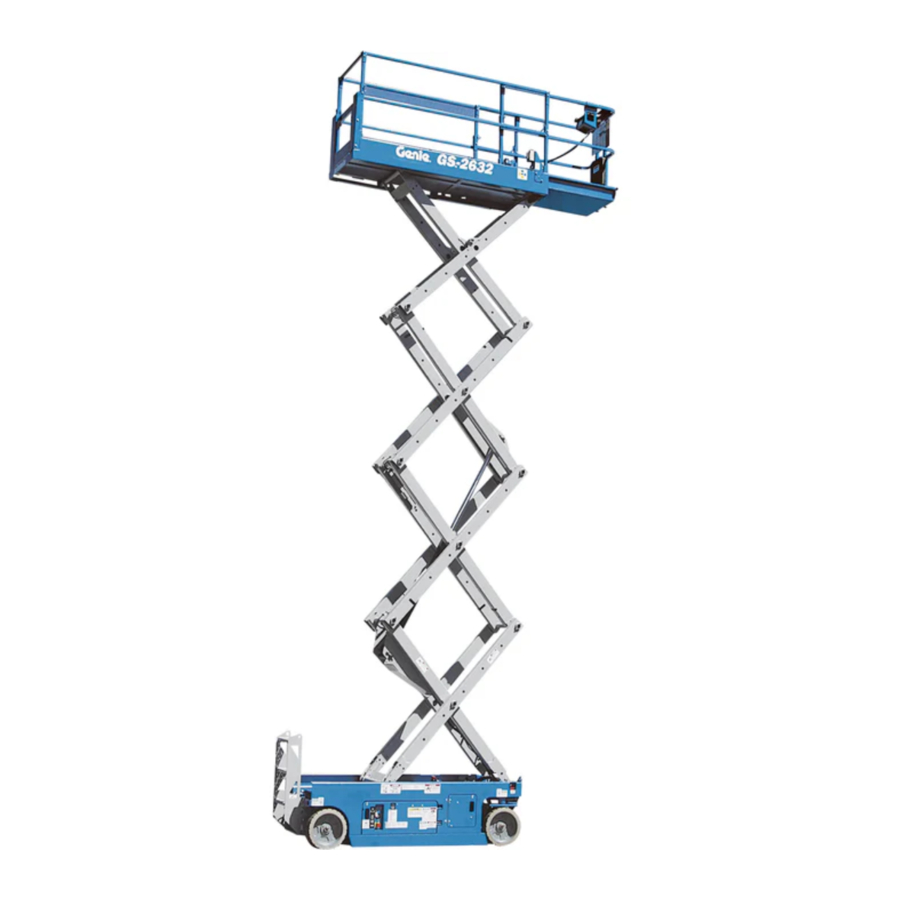
Genie GS-2032, GS-2632 Manual
- Operator's manual (38 pages) ,
- Operators manual with maintenance information (38 pages) ,
- Service and repair manual (343 pages)
Advertisement
- 1 Safety Rules
- 2 Legend
- 3 Controls
- 4 Pre-operation Inspection
- 5 Maintenance
- 6 Function Tests
- 7 Workplace Inspection
-
8
Operating Instructions
- 8.1 Emergency Stop
- 8.2 Auxiliary Lowering
- 8.3 Operation From Ground
- 8.4 Operation From Platform
- 8.5 To Extend and Retract Platform
- 8.6 Operation From Ground with Controller
- 8.7 After Each Use
- 8.8 Battery and Charger Instructions
- 8.9 To Charge Battery
- 8.10 Dry Battery Filling and Charging Instructions
- 9 Transport and Lifting Instructions
- 10 Decals
- 11 Specifications
- 12 Documents / Resources
Safety Rules

Failure to obey the instructions and safety rules in this manual will result in death or serious injury.
Do Not Operate Unless:
![]() You learn and practice the principles of safe machine operation contained in this operator's manual.
You learn and practice the principles of safe machine operation contained in this operator's manual.
- Avoid hazardous situations. Know and understand the safety rules before going on to the next section.
- Always perform a pre-operation inspection.
- Always perform function tests prior to use.
- Inspect the workplace.
- Only use the machine as it was intended.
![]() You read, understand and obey the manufacturer's instructions and safety rules— safety and operator's manuals and machine decals.
You read, understand and obey the manufacturer's instructions and safety rules— safety and operator's manuals and machine decals.
![]() You read, understand and obey employer's safety rules and worksite regulations.
You read, understand and obey employer's safety rules and worksite regulations.
![]() You read, understand and obey all applicable governmental regulations.
You read, understand and obey all applicable governmental regulations.
![]() You are properly trained to safely operate the machine.
You are properly trained to safely operate the machine.
Electrocution Hazards
This machine is not electrically insulated and will not provide protection from contact with or proximity to electrical current.

Maintain safe distances from electrical power lines and apparatus in accordance with applicable governmental regulations and the following chart.
| Voltage Phase to Phase | Minimum Safe Approach Distance | |
| Feet | Meters | |
| 0 to 300V | Avoid Contact | |
| 300V to 50KV | 10 | 3.05 |
| 50KV to 200KV | 15 | 4.60 |
| 200KV to 350KV | 20 | 6.10 |
| 350KV to 500KV | 25 | 7.62 |
| 500KV to 750KV | 35 | 10.67 |
| 750KV to 1000KV | 45 | 13.72 |
Allow for platform movement, electrical line sway or sag and beware of strong or gusty winds.
Keep away from the machine if it contacts energized power lines. Personnel on the ground or in the platform must not touch or operate the machine until energized power lines are shut off.
Do not operate the machine during lightning or storms.
Do not use the machine as a ground for welding.
Tip-over Hazards
Occupants, equipment and materials must not exceed the maximum platform capacity or the maximum capacity of the platform extension.
| Maximum capacity - GS-2032 | ||
| Platform retracted | 800 lbs | 363 kg |
| Platform extended - Platform only | 550 lbs | 249 kg |
| Platform extended - Extension only | 250 lbs | 113 kg |
| Maximum occupants - ANSI and CSA | 2 | |
| Maximum occupants - Australia Outdoor use | 1 | |
| Indoor use only | 2 | |

| Maximum capacity - GS-2632 | ||
| Platform retracted | 500 lbs | 227 kg |
| Platform extended - Platform only | 250 lbs | 113 kg |
| Platform extended - Extension only | 250 lbs | 113 kg |
| Maximum occupants - ANSI and CSA | 2 | |
| Maximum occupants - Australia Indoor use only | 2 | |

Do not raise the platform unless the machine is on a firm, level surface.

Do not depend on the tilt alarm as a level indicator. The tilt alarm sounds on the chassis only when the machine is on a slope.
If the tilt alarm sounds:
Lower the platform. Move the machine to a firm, level surface. If the tilt alarm sounds when the platform is raised, use extreme caution to lower the platform.
Do not alter or disable the limit switches.
Do not drive over 0.5 mph / 0.7 km/h with the platform raised.
Do not operate the machine in strong or gusty winds. Do not increase the surface area of the platform or the load. Increasing the area exposed to the wind will decrease machine stability.

Do not drive the machine on or near uneven terrain, unstable surfaces or other hazardous conditions with the platform raised.
Use extreme care and slow speeds while driving the machine in a stowed position across uneven terrain, debris, unstable or slippery surfaces and near holes and drop-offs.
Do not push off or pull toward any object outside of the platform.

Do not alter or disable machine components that in any way affect safety and stability.
Do not place or attach fixed or overhanging loads to any part of this machine.

Do not transport tools and materials unless they are evenly distributed and can be safely handled by person(s) in the platform.
Do not place ladders or scaffolds in the platform or against any part of this machine.
Do not modify or alter an aerial work platform without prior written permission from the manufacturer. Mounting attachments for holding tools or other materials onto the platform, toeboards or guard rail system can increase the weight in the platform and the surface area of the platform or the load.
Maximum allowable manual force
| GS-2032 | |
| ANSI & CSA - 2 person | 120 lbs / 534 N |
| Australia - Indoor use only - 2 person | 90 lbs / 400 N |
| Australia - Outdoor use - 1 person | 45 lbs / 200 N |
| GS-2632 | |
| ANSI & CSA - 2 person | 100 lbs / 445 N |
| Australia - Indoor use only - 2 person | 90 lbs / 400 N |
Do not replace items critical to machine stability with items of different weight or specification.
Do not use the machine on a moving or mobile surface or vehicle.
Be sure all tires are in good condition, castle nuts are properly tightened and cotter pins are properly installed.
Do not use batteries that weigh less than the original equipment. Batteries are used as counterweight and are critical to machine stability. Each battery must weigh 65 pounds / 30 kg.
Do not use the machine as a crane.
Do not push the machine or other objects with the platform.
Do not contact adjacent structures with the platform.
Do not tie the platform to adjacent structures.
Do not place loads outside the platform perimeter.
Do not operate the machine with the chassis trays open.
Do not use the platform controls to free a platform that is caught, snagged or otherwise prevented from normal motion by an adjacent structure. All personnel must be removed from the platform before attempting to free the platform using the ground controls.
Fall Hazards
The guard rail system provides fall protection. If occupants of the platform are required to wear personal fall protection equipment (PFPE) due to job site or employer rules, PFPE equipment and its use shall be in accordance with the PFPE manufacturer's instructions and applicable governmental requirements.
Do not sit, stand or climb on the platform guard rails. Maintain a firm footing on the platform floor at all times.

Do not climb down from the platform when raised. Keep the platform floor clear of debris.
Attach the platform entry chain or close the entry gate before operating.
Do not operate the machine unless the guard rails are properly installed and the entry is secured for operation.
Collision Hazards

Be aware of limited sight distance and blind spots when driving or operating.
Be aware of the extended platform position when moving the machine.
The machine must be on a level surface or secured before releasing the brakes.
Operators must comply with employer, job site and governmental rules regarding use of personal protective quipment.

Check the work area for overhead obstructions or other possible hazards.
Be aware of crushing hazards when grasping the platform guard rail.
Observe and use the color-coded direction arrows on the platform controls and platform decal plate for drive and steer functions.
No stunt driving or horseplay while operating a machine.

Do not lower the platform unless the area below is clear of personnel and obstructions.
Limit travel speed according to the condition of the ground surface, congestion, slope, location of personnel, and any other factors which may cause collision.
Do not operate a machine in the path of any crane or moving overhead machinery unless the controls of the crane have been locked out and/or precautions have been taken to prevent any potential collision.
Crushing Hazards
Keep hands and limbs out of scissors.
Use common sense and planning when operating the machine with the controller from the ground. Maintain safe distances between the operator, the machine and fixed objects.
Component Damage Hazard
Do not use the machine as a ground for welding.
Explosion and Fire Hazard
Do not operate the machine in hazardous locations or locations where potentially flammable or explosive gases or particles may be present.
Damaged Machine Hazards
Do not use a damaged or malfunctioning machine.
Conduct a thorough pre-operation inspection of the machine and test all functions before each work shift. Immediately tag and remove from service a damaged or malfunctioning machine.
Be sure all maintenance has been performed as specified in this manual and the appropriate service manual.
Be sure all decals are in place and legible.
Be sure the operator's, safety, and responsibilities manuals are complete, legible and in the storage container located on the platform.
Bodily Injury Hazard
Do not operate the machine with a hydraulic oil or air leak. An air leak or hydraulic leak can penetrate and/or burn skin.
Improper contact with components under any cover will cause serious injury. Only trained maintenance personnel should access compartments. Access by the operator is only advised when performing a pre-operation inspection. All compartments must remain closed and secured during operation.
Decal Legend
Genie product decals use symbols, color coding and signal words to identify the following:
 Safety alert symbol—used to alert personnel to potential personal injury hazards. Obey all safety messages that follow this symbol to avoid possible injury or death.
Red—used to indicate the presence of an imminently hazardous situation which, if not avoided, will result in death or serious injury.

Orange—used to indicate the presence of a potentially hazardous situation which, if not avoided, could result in death or serious injury.

Yellow with safety alert symbol— used to indicate the presence of a potentially hazardous situation which, if not avoided, may cause minor or moderate injury.
 Yellow without safety alert symbol—used to indicate the presence of a potentially hazardous situation which, if not avoided, may result in property damage.
 NOTICE Green—used to indicate operation or maintenance information.
Battery Safety
Burn Hazards
Batteries contain acid. Always wear protective clothing and eye wear when working with batteries.

Avoid spilling or contacting battery acid. Neutralize battery acid spills with baking soda and water.
Do not expose the batteries or the charger to water or rain during charging.
Explosion Hazards

Keep sparks, flames and lighted tobacco away from batteries. Batteries emit an explosive gas.
The battery tray should remain open during the entire charging cycle.
Do not contact the battery terminals or the cable clamps with tools that may cause sparks.
Component Damage Hazard
Do not use any battery charger greater than 24V to charge the batteries.
Electrocution Hazards

Connect the battery charger to a grounded, AC 3-wire electrical outlet only. Inspect daily for damaged cord, cables and wires. Replace damaged items before operating.
Avoid electrical shock from contact with battery terminals. Remove all rings, watches and other jewelry.
Tip-over Hazard
Do not use batteries that weigh less than the original equipment. Batteries are used as counterweight and are critical to machine stability. Each battery must weigh 65 pounds / 30 kg.
Lifting Hazard
Use the appropriate number of people and proper lifting techniques when lifting batteries.
Legend

- Platform entry chain or entry gate
- Platform guard rails
- Lanyard anchorage point
- Platform extension release pedal
- GFCI outlet
- Platform controls
- Manual storage container
- Tilt alarm (under cover)
- Auxiliary lowering lever
- Transport tie-down
- Steer tire
- Pothole guard
- LED diagnostic readout
- Ground controls
- Non-steer tire
- Brake release pump knob and release knob
- Battery charger (on opposite side of machine)
- Entry ladder/transport tie-down
- Safety arm
Controls

Ground Control Panel
- 7 amp breaker for electrical circuits
- Key switch for platform/off/ground selection
- Hour meter
- Platform up/down toggle switch
- Red Emergency Stop button

Platform Controls
- Horn button
- Machine on incline symbol: Low speed operation for inclines
- Lift function select button with indicator light
- Drive function select button with indicator light
- Red Emergency Stop button
- Function enable switch
- Proportional control handle for lift and drive functions and thumb rocker for steer function
- Error indicator light
- Power light
- Battery level indicator
Pre-operation Inspection
Do Not Operate Unless:
![]() You learn and practice the principles of safe machine operation contained in this operator's manual.
You learn and practice the principles of safe machine operation contained in this operator's manual.
- Avoid hazardous situations.
- Always perform a pre-operation inspection. Know and understand the pre-operation inspection before going on to the next section.
- Always perform function tests prior to use.
- Inspect the workplace.
- Only use the machine as it was intended.
Fundamentals
It is the responsibility of the operator to perform a pre-operation inspection and routine maintenance.
The pre-operation inspection is a visual inspection performed by the operator prior to each work shift. The inspection is designed to discover if anything is apparently wrong with a machine before the operator performs the function tests.
The pre-operation inspection also serves to determine if routine maintenance procedures are required. Only routine maintenance items specified in this manual may be performed by the operator.
Refer to the list on the next page and check each of the items.
If damage or any unauthorized variation from factory delivered condition is discovered, the machine must be tagged and removed from service.
Repairs to the machine may only be made by a qualified service technician, according to the manufacturer's specifications. After repairs are completed, the operator must perform a pre-operation inspection again before going on to the function tests.
Scheduled maintenance inspections shall be performed by qualified service technicians, according to the manufacturer's specifications and the requirements listed in the responsibilities manual.
Pre-operation Inspection
- Be sure that the operator's, safety and responsibilities manuals are complete, legible and in the storage container located on the platform.
- Be sure that all decals are legible and in place. See Decals section.
- Check for hydraulic oil leaks and proper oil level. Add oil if needed. See Maintenance section.
- Check for battery fluid leaks and proper fluid level. Add distilled water if needed. See Maintenance section.
Check the following components or areas for damage, improperly installed or missing parts and unauthorized modifications:
- Electrical components, wiring and electrical cables
- Hydraulic power unit, tank, hoses, fittings, cylinders and manifolds
- Battery pack and connections
- Drive motors
- Wear pads
- Tires and wheels
- Ground strap
- Limit switches, alarms and horn
- Nuts, bolts and other fasteners
- Platform entry chain (if equipped)
- Platform entry gate (if equipped)
- Beacon and alarms (if equipped)
- Brake release components
- Safety arm
- Pothole guards
- Platform extension
- Scissor pins and retaining fasteners
- Platform control joystick
- Generator (if equipped)
Check entire machine for:
- Cracks in welds or structural components
- Dents or damage to machine
- Be sure that all structural and other critical components are present and all associated fasteners and pins are in place and properly tightened.
- Side rails are installed and bolts are fastened
- Be sure that the chassis trays are in place, latched and properly connected.
Maintenance
Observe and Obey:
![]() Only routine maintenance items specified in this manual shall be performed by the operator.
Only routine maintenance items specified in this manual shall be performed by the operator.
![]() Scheduled maintenance inspections shall be completed by qualified service technicians, according to the manufacturer's specifications and the requirements specified in the responsibilities manual.
Scheduled maintenance inspections shall be completed by qualified service technicians, according to the manufacturer's specifications and the requirements specified in the responsibilities manual.
Maintenance Symbols Legend
NOTICE The following symbols have been used in this manual to help communicate the intent of the instructions. When one or more of the symbols appear at the beginning of a maintenance procedure, it conveys the meaning below.
![]() Indicates that tools will be required to perform this procedure.
Indicates that tools will be required to perform this procedure.
![]() Indicates that new parts will be required to perform this procedure.
Indicates that new parts will be required to perform this procedure.
Check the Hydraulic Oil Level
![]() Maintaining the hydraulic oil at the proper levels is essential to machine operation. Improper hydraulic oil levels can damage hydraulic components. Daily checks allow the inspector to identify changes in oil level that might indicate the presence of hydraulic system problems.
Maintaining the hydraulic oil at the proper levels is essential to machine operation. Improper hydraulic oil levels can damage hydraulic components. Daily checks allow the inspector to identify changes in oil level that might indicate the presence of hydraulic system problems.
NOTICE Perform this procedure with the platform in the stowed position.
- Visually inspect the oil level in the hydraulic tank.
![]() Result: The hydraulic oil level should be at the FULL mark on the tank.
Result: The hydraulic oil level should be at the FULL mark on the tank. - Add oil if necessary. Do not overfill.
| Hydraulic oil specifications | |
| Hydraulic oil type | Chevron Rykon Premium MV equivalent |
Check the Batteries
![]() Proper battery condition is essential to good performance and operational safety. Improper fluid levels or damaged cables and connections can result in component damage and hazardous conditions.
Proper battery condition is essential to good performance and operational safety. Improper fluid levels or damaged cables and connections can result in component damage and hazardous conditions.
NOTICE This procedure does not need to be performed on machines with sealed or maintenance-free batteries.

Electrocution hazard. Contact with hot or live circuits may result in death or serious injury. Remove all rings, watches and other jewelry.
Bodily injury hazard. Batteries contain acid. Avoid spilling or contacting battery acid. Neutralize battery acid spills with baking soda and water.
NOTICE Perform this test after fully charging the batteries.
- Put on protective clothing and eye wear.
- Be sure that the battery cable connections are tight and free of corrosion.
- Be sure that the battery retaining fasteners are in place and secure.
- Remove the battery vent caps.
- Check the battery acid level of each battery. If needed, replenish with distilled water to the bottom of the battery fill tube. Do not overfill.
- Install the vent caps.
Scheduled Maintenance
Maintenance performed quarterly, annually and every two years must be completed by a person trained and qualified to perform maintenance on this machine according to the procedures found in the service manual for this machine.
Machines that have been out of service for more than three months must receive the quarterly inspection before they are put back into service.
Function Tests
Do Not Operate Unless:
![]() You learn and practice the principles of safe machine operation contained in this operator's manual.
You learn and practice the principles of safe machine operation contained in this operator's manual.
- Avoid hazardous situations.
- Always perform a pre-operation inspection.
- Always perform function tests prior to use. Know and understand the function tests before going on to the next section.
- Inspect the workplace.
- Only use the machine as it was intended.
Fundamentals
The function tests are designed to discover any malfunctions before the machine is put into service. The operator must follow the step-by-step instructions to test all machine functions.
A malfunctioning machine must never be used. If malfunctions are discovered, the machine must be tagged and removed from service. Repairs to the machine may only be made by a qualified service technician, according to the manufacturer's specifications.
After repairs are completed, the operator must perform a pre-operation inspection and function tests again before putting the machine into service.
- Select a test area that is firm, level and free of obstruction.
- Be sure the battery pack is connected.
At the Ground Controls
- Pull out the platform and ground red Emergency Stop buttons to the on position.
- Turn the key switch to ground control.
- Observe the diagnostic LED readout.
![]() Result: LED should read 23 or --.
Result: LED should read 23 or --.
Test Emergency Stop
- Push in the ground red Emergency Stop button to the off position.
![]() Result: No functions should operate.
Result: No functions should operate. - Pull out the red Emergency Stop button to the on position.
Test the Up/Down Functions
The audible warnings on this machine and the standard horn all come from the same central alarm. The horn is a constant tone. The descent alarm sounds at 60 beeps per minute. The alarm that goes off when the pothole guards have not deployed sounds at 300 beeps per minute. The alarm that goes off when the machine is not level sounds at 600 beeps per minute. An optional automotive-style horn is also available.
- Activate the up function.
![]() Result: The platform should raise.
Result: The platform should raise. - Activate the down function.
![]() Result: The platform should lower. The descent alarm should sound while the platform is lowering.
Result: The platform should lower. The descent alarm should sound while the platform is lowering.
Test Auxiliary Lowering
- Activate the up function and raise the platform approximately 2 feet / 60 cm.
- Pull the auxiliary lowering knob.
![]() Result: The platform should lower. The descent alarm will not sound.
Result: The platform should lower. The descent alarm will not sound. - Turn the key switch to platform control.
At the Platform Controls
Test Emergency Stop
- Push in the platform red Emergency Stop button to the off position.
![]() Result: No functions should operate.
Result: No functions should operate.
Test the Horn
- Pull the red Emergency Stop button out to the on position.
- Push the horn button.
![]() Result: The horn should sound.
Result: The horn should sound.
Test the Function Enable Switch
- Do not hold the function enable switch on the control handle.
- Slowly move the control handle in the direction indicated by the blue arrow, then in the direction indicated by the yellow arrow.
![]() Result: No functions should operate.
Result: No functions should operate.
Test the Up/Down Functions
- Press the lift function select button.
- Press and hold the function enable switch on the control handle.
- Slowly move the control handle in the direction indicated by the blue arrow.
![]() Result: The platform should raise. The pothole guards should deploy.
Result: The platform should raise. The pothole guards should deploy. - Release the control handle.
![]() Result: The platform should stop raising.
Result: The platform should stop raising. - Press and hold the function enable switch. Slowly move the control handle in the direction indicated by the yellow arrow.
![]() Result: The platform should lower. The descent alarm should sound while the platform is lowering.
Result: The platform should lower. The descent alarm should sound while the platform is lowering.
Test the Steering
Note: When performing the steer and drive function tests, stand in the platform facing the steer end of the machine.
- Press the drive function select switch.
- Press and hold the function enable switch on the control handle.
- Depress the thumb rocker switch on top of the control handle in the direction identified by the blue triangle on the control panel.
![]() Result: The steer wheels should turn in the direction that the blue triangle points on the control panel.
Result: The steer wheels should turn in the direction that the blue triangle points on the control panel. - Depress the thumb rocker switch in the direction identified by the yellow triangle on the control panel.
![]() Result: The steer wheels should turn in the direction that the yellow triangle points on the control panel.
Result: The steer wheels should turn in the direction that the yellow triangle points on the control panel.
Test Drive and Braking
- Press and hold the function enable switch on the control handle.
- Slowly move the control handle in the direction indicated by the blue arrow on the control panel until the machine begins to move, then return the handle to the center position.
![]() Result: The machine should move in the direction that the blue arrow points on the control panel, then come to an abrupt stop.
Result: The machine should move in the direction that the blue arrow points on the control panel, then come to an abrupt stop. - Slowly move the control handle in the direction indicated by the yellow arrow on the control panel until the machine begins to move, then return the handle to the center position.
![]() Result: The machine should move in the direction that the yellow arrow points on the control panel, then come to an abrupt stop.
Result: The machine should move in the direction that the yellow arrow points on the control panel, then come to an abrupt stop.
Note: The brakes must be able to hold the machine on any slope it is able to climb.
Test Limited Drive Speed
- Press the lift function select button.
- Press and hold the function enable switch on the control handle. Raise the platform approximately 4 feet / 1.2 m from the ground.
![]() Result: The pothole guards should deploy.
Result: The pothole guards should deploy. - Press the drive function select switch.
- Press and hold the function enable switch on the control handle. Slowly move the control handle to the full drive position.
![]() Result: The maximum achievable drive speed with the platform raised should not exceed 0.75 feet / 23 cm per second.
Result: The maximum achievable drive speed with the platform raised should not exceed 0.75 feet / 23 cm per second.
If the drive speed with the platform raised exceeds 0.75 feet / 23 cm per second, immediately tag and remove the machine from service.
Test the Tilt Sensor Operation
Note: Perform this test from the ground with the platform controller. Do not stand in the platform.
- Fully lower the platform.
- Place a 2x4 or similar piece of wood under both wheels on one side and drive the machine up onto them.
- Raise the platform approximately 7 feet / 2.1 m from the ground.
![]() Result: The platform should stop and the tilt alarm will sound at 600 beeps per minute.
Result: The platform should stop and the tilt alarm will sound at 600 beeps per minute. - Move the drive control handle in the direction indicated by the blue arrow, then move the drive control handle in the direction indicated by the yellow arrow.
![]() Result: The drive function should not work in either direction.
Result: The drive function should not work in either direction. - Lower the platform and remove both pieces of wood.
Test the Pothole Guards
Note: The pothole guards should automatically deploy when the platform is raised. The pothole guards activate two limit switches which control the machine drive speed. If the pothole guards do not deploy and the platform is raised above 6 feet / 1.8 m, an alarm sounds and the machine will not drive.
- Raise the platform.
![]() Result: When the platform is raised 4 feet / 1.2 m from the ground, the pothole guards should deploy.
Result: When the platform is raised 4 feet / 1.2 m from the ground, the pothole guards should deploy. - Press on the pothole guards on one side, and then the other.
![]() Result: The pothole guards should not move.
Result: The pothole guards should not move. - Lower the platform.
![]() Result: The pothole guards should return to the stowed position.
Result: The pothole guards should return to the stowed position. - Place a 2x4 or similar piece of wood under a pothole guard. Raise the platform.
![]() Result: Before the platform is raised 7 feet / 2.1 m from the ground, an alarm should sound and the drive function should not work.
Result: Before the platform is raised 7 feet / 2.1 m from the ground, an alarm should sound and the drive function should not work. - Lower the platform and remove the 2x4.
Workplace Inspection
Do Not Operate Unless:
![]() You learn and practice the principles of safe machine operation contained in this operator's manual.
You learn and practice the principles of safe machine operation contained in this operator's manual.
- Avoid hazardous situations.
- Always perform a pre-operation inspection.
- Always perform function tests prior to use.
- Inspect the workplace. Know and understand the workplace inspection before going on to the next section.
- Only use the machine as it was intended.
Fundamentals
The workplace inspection helps the operator determine if the workplace is suitable for safe machine operation. It should be performed by the operator prior to moving the machine to the workplace.
It is the operator's responsibility to read and remember the workplace hazards, then watch for and avoid them while moving, setting up and operating the machine.
Workplace Inspection
Be aware of and avoid the following hazardous situations:
- drop-offs or holes
- bumps, floor obstructions or debris
- sloped surfaces
- unstable or slippery surfaces
- overhead obstructions and high voltage conductors
- hazardous locations
- inadequate surface support to withstand all load forces imposed by the machine
- wind and weather conditions
- the presence of unauthorized personnel
- other possible unsafe conditions
Operating Instructions
Do Not Operate Unless:
![]() You learn and practice the principles of safe machine operation contained in this operator's manual.
You learn and practice the principles of safe machine operation contained in this operator's manual.
- Avoid hazardous situations.
- Always perform a pre-operation inspection.
- Always perform function tests prior to use.
- Inspect the workplace.
- Only use the machine as it was intended.
Fundamentals
The Operating Instructions section provides instructions for each aspect of machine operation. It is the operator's responsibility to follow all the safety rules and instructions in the operator's, safety and responsibilities manuals.
Using the machine for anything other than lifting personnel, along with their tools and materials, to an aerial work site is unsafe and dangerous.
Only trained and authorized personnel should be permitted to operate a machine. If more than one operator is expected to use a machine at different times in the same work shift, they must all be qualified operators and are all expected to follow all safety rules and instructions in the operator's, safety and responsibilities manuals. That means every new operator should perform a pre-operation inspection, function tests, and a workplace inspection before using the machine.
Emergency Stop
Push in the red Emergency Stop button to the off position at the ground controls or the platform controls to stop all functions.
Repair any function that operates when either red Emergency Stop button is pushed in.
Auxiliary Lowering
- Pull the auxiliary lowering knob.
Operation From Ground
- Turn the key switch to ground control.
- Pull out both ground and platform red Emergency Stop buttons to the on position.
- Be sure the battery pack is connected before operating the machine.
To Position Platform
- Move the up/down toggle switch according to the markings on the control panel.
Drive and steer functions are not available from the ground controls.
Operation From Platform
- Turn the key switch to platform control.
- Pull out the ground and platform red Emergency Stop buttons to the on position.
- Be sure the battery pack is connected before operating the machine.
To Position Platform
- Press the lift function select button.
- Press and hold the function enable switch on the control handle.
- Move the control handle according to the markings on the control panel.
To Steer
- Press the drive function select button.
- Press and hold the function enable switch on the control handle.
- Turn the steer wheels with the thumb rocker switch located on the top of the control handle.
To Drive
- Press the drive function select button.
- Press and hold the function enable switch on the control handle.
- Increase speed: Slowly move the control handle off center.
Decrease speed: Slowly move the control handle toward center.
Stop: Return the control handle to center or release the function enable switch.
Use the color-coded direction arrows on the platform controls and on the platform to identify the direction the machine will travel.
Machine travel speed is restricted when the platform is raised.
Battery condition will affect machine performance. Machine drive speed and function speed will drop when the low battery indicator light is on or when the last light on the battery level indicator is flashing.
Error Indicator Light On
 If the error indicator light is on, push in and pull out the red Emergency Stop button to reset the system.
If the light stays on, tag and remove the machine from service.
Drive Select Switch

Machine on incline symbol:
Low range operation for inclines
To Extend and Retract Platform
- Step on the platform extension release pedal on the platform toeboard.
- Grasp the platform guard rails and carefully push to extend the platform to the mid-position stop.
- Step on the release pedal again and push to fully extend the platform.
Do not stand on the platform extension while trying to extend it.
- Step on the platform extension release pedal and pull to retract the platform to the midposition stop. Step again to fully retract the platform.
Operation From Ground with Controller
Maintain safe distances between the operator, machine and fixed objects.
Be aware of the direction the machine will travel when using the controller.
After Each Use
- Select a safe parking location—firm level surface, clear of obstruction and traffic.
- Lower the platform.
- Turn the key switch to the off position and remove the key to secure from unauthorized use.
- Chock the wheels.
- Charge the batteries.
Battery and Charger Instructions
Observe and Obey:
![]() Do not use an external charger or booster battery. Charge the battery in a well-ventilated area.
Do not use an external charger or booster battery. Charge the battery in a well-ventilated area.
![]() Use proper AC input voltage for charging as indicated on the charger.
Use proper AC input voltage for charging as indicated on the charger.
![]() Use only Genie authorized battery and charger.
Use only Genie authorized battery and charger.
To Charge Battery
- Be sure the batteries are connected before charging the batteries.
- Open the battery compartment. The compartment should remain open for the entire charging cycle.
- Remove the battery vent caps and check the battery acid level. If necessary, add only enough distilled water to cover the plates. Do not overfill prior to the charge cycle.
- Replace the battery vent caps.
- Connect the battery charger to a grounded AC circuit.
- The charger will indicate when the battery is fully charged.
- Check the battery acid level when the charging cycle is complete. Replenish with distilled water to the bottom of the fill tube. Do not overfill.
Dry Battery Filling and Charging Instructions
- Remove the battery vent caps and permanently remove the plastic seal from the battery vent openings.
- Fill each cell with battery acid (electrolyte) until the level is sufficient to cover the plates. Do not fill to the maximum level until the battery charge cycle is complete. Overfilling can cause the battery acid to overflow during charging. Neutralize battery acid spills with baking soda and water.
- Install the battery vent caps.
- Charge the battery.
- Check the battery acid level when the charging cycle is complete. Replenish with distilled water to the bottom of the fill tube. Do not overfill.
Transport and Lifting Instructions
Observe and Obey:
Common sense and planning must be applied to control the movement of the machine when lifting it with a crane or forklift.
![]() The transport vehicle must be parked on a level surface.
The transport vehicle must be parked on a level surface.
![]() The transport vehicle must be secured to prevent rolling while the machine is being loaded.
The transport vehicle must be secured to prevent rolling while the machine is being loaded.
![]() Be sure the vehicle capacity, loading surfaces and chains or straps are sufficient to withstand the machine weight. See the serial plate for the machine weight.
Be sure the vehicle capacity, loading surfaces and chains or straps are sufficient to withstand the machine weight. See the serial plate for the machine weight.
![]() The machine must be on a level surface or secured before releasing the brakes.
The machine must be on a level surface or secured before releasing the brakes.
![]() Do not allow the rails to fall when the snap pins are removed. Maintain a firm grasp on the rails when the rails are lowered.
Do not allow the rails to fall when the snap pins are removed. Maintain a firm grasp on the rails when the rails are lowered.
Brake Release Operation

- Chock the wheels to prevent the machine from rolling.
- Be sure the winch line is properly secured to the drive chassis tie points and the path is clear of all obstructions.
- Before serial number GS04-52789: Turn the black brake release knob counterclockwise to open the brake valve. After serial number GS04-52788: Push in the black brake release knob to open the brake valve.
- Pump the red brake release pump knob.
After the machine is loaded:
- Chock the wheels to prevent the machine from rolling.
- Before serial number GS04-52789: Turn the brake release knob clockwise to close the brake valve. After serial number GS04-52788: Press the drive function select button. Press and hold the function enable switch on the control handle. Move the control handle off center to reset the brakes.
Towing the Genie GS-2032 and the GS-2632 is not recommended. If the machine must be towed, do not exceed 2 mph / 3.2 km/h.
Observe and Obey:
![]() Only qualified riggers should rig and lift the machine.
Only qualified riggers should rig and lift the machine.
![]() Be sure the crane capacity, loading surfaces and straps or lines are sufficient to withstand the machine weight. See the serial plate for the machine weight.
Be sure the crane capacity, loading surfaces and straps or lines are sufficient to withstand the machine weight. See the serial plate for the machine weight.
Lifting Instructions
Fully lower the platform. Be sure the extension deck, controls and component trays are secure. Remove all loose items on the machine.
Determine the center of gravity of your machine using the table and the picture on this page.
Attach the rigging only to the designated lifting points on the machine. There are two 1 inch / 2.5 cm holes on the front of the machine and two holes in the ladder for lifting.
Adjust the rigging to prevent damage to the machine and to keep the machine level.

| Center of gravity | X Axis | Y Axis |
| ANSI and CSA models | ||
| GS-2032 | 35.6 in 90.5 cm | 22.2 in 56.5 cm |
| GS-2632 | 31.7 in 80.6 cm | 22.7 in 57.6 cm |
| Australia models | ||
| GS-2032 | 31.9 in 80.9 cm | 21.2 in 53.9 cm |
| GS-2632 | 32.4 in 82.2 cm | 23.3 in 59.3 cm |
Securing to Truck or Trailer for Transit

Always use the extension deck lock when the machine is transported.
Turn the key switch to the off position and remove the key before transporting.
Inspect the entire machine for loose or unsecured items.
Use chains or straps of ample load capacity.
Use a minimum of 2 chains or straps.
Adjust the rigging to prevent damage to the chains.
Decals
Inspection for Decals with Words
Determine whether the decals on your machine have words or symbols. Use the appropriate inspection to verify that all decals are legible and in place.

| Part No. | Description Quantity | |
| 28164 | Notice - Hazardous Materials | 1 |
| 28171 | Label - No Smoking | 1 |
| 28174 | Label - Power to Platform, 230V | 2 |
| 28175 | Caution - Compartment Access | 1 |
| 28176 | Notice - Missing Manuals | 1 |
| 28235 | Label - Power to Platform, 115V | 2 |
| 28236 | Warning - Failure To Read. . . | 1 |
| 31060 | Danger - Do Not Alter Limit Switch | 1 |
| 31508 | Notice - Power to Battery Charger | 1 |
| 40434 | Label - Lanyard Anchorage | 5 |
| 43089 | Notice - Operating Instructions, Ground | 1 |
| 43090 | Notice - Operating Instructions, Platform | 1 |
| 43091 | Danger - General Safety Rules | 1 |
| 43617 | Danger - Tip-over (batteries) | 1 |
| 43618 | Label - Directional Arrows | 2 |
| 43619 | Label - Safety Arm | 1 |
| 43658 | Label - Power to Charger, 230V | 1 |
| 43696 | Danger - Electrocution Hazard | 2 |
| 44255 | Danger - Crushing Hazard | 4 |
| 44736 | Danger - Tilt Alarm | 1 |
| 44737 | Danger - Tip-over, Trays Open | 2 |
| 44753 | Label - LED Diagnostic Readout | 1 |
| 44980 | Label - Power to Charger, 115V | 1 |
| 46238 | Notice - Error Indicator Light | 1 |
| 46262 | Danger - Battery/Charger Safety | 1 |
| 46287 | Notice - Tire Specification | 4 |
| 52475 | Label - Transport Tie-down | 5 |
| 62055 | Cosmetic - Genie GS-2032 | 2 |
| 65052 | Label - ECU Fault Codes | 1 |
| 65058 | Label - Controller Identification | 1 |
| 72853 | Danger - Improper Use Hazard | 1 |
| 72970 | Notice - Battery Charger Operating Instructions | 1 |
| 72973 | Cosmetic - Genie GS-2632 | 2 |
| 78673 | Platform Control Panel | 1 |
| 82307 | Notice - Side Force, GS-2632, Australia | 1 |
| 82366 | Label - Chevron Rykon | 1 |
| 82447 | Label - Auxiliary Lowering | 1 |
| 82557 | Label - Platform Controls Location | 1 |
| 82558 | Warning - Skin Injection Hazard | 1 |
| 82559 | Notice - Annual Inspection | 1 |
| 82561 | Danger - Crushing Hazard | 2 |
| 82563 | Notice - Max Cap 500 lbs / 227 kg, GS-2632 | 1 |
| 82567 | Ground Control Panel | 1 |
| 82569 | Danger/Notice - Brake Release Safety & Operating Instructions | 1 |
| 82657 | Notice - Battery Connection Diagram | 1 |
| 82693 | Notice - Max Cap 800 lbs / 363 kg, GS-2032 | 1 |
| 82694 | Notice - Side Force, GS-2032, ANSI & CSA 1 | 1 |
| 82695 | Notice - Side Force, GS-2632, ANSI & CSA 1 | 1 |
| 97692 | Label - Wheel Load, GS-2032 | 4 |
| 97693 | Label - Wheel Load, GS-2632 | 4 |
| 97694 | Notice - Side Force, GS-2032, Australia | 1 |
| 97712 |  Danger/Notice - Brake Release Safety & Operating Instructions Danger/Notice - Brake Release Safety & Operating Instructions | 1 |
Inspection for Decals with Symbols
Determine whether the decals on your machine have words or symbols. Use the appropriate inspection to verify that all decals are legible and in place.

| Part No. | Description | Quantity |
| 28174 | Label - Power to Platform, 230V | 2 |
| 28235 | Label - Power to Platform, 115V | 2 |
| 40434 | Label - Lanyard Anchorage | 5 |
| 43618 | Label - Directional Arrows | 2 |
| 43658 | Label - Power to Charger, 230V | 1 |
| 44980 | Label - Power to Charger, 115V | 1 |
| 52475 | Label - Transport Tie-down | 5 |
| 62055 | Cosmetic - Genie GS-2032 | 2 |
| 65058 | Label - Controller Indentification | 1 |
| 72973 | Cosmetic - Genie GS-2632 | 2 |
| 78673 | Platform Control Panel | 1 |
| 82472 | Warning - Crushing Hazard | 1 |
| 82474 | Warning - Safety Chock | 2 |
| 82476 | Danger - Electrocution Hazard | 2 |
| 82481 | Danger - Battery/Charger Safety | 1 |
| 82482 | Label - Auxiliary Lowering | 1 |
| 82487 | Notice - Read the Manual | 2 |
| 82488 | Notice - Error Indicator Light | 1 |
| 82495 | Danger - Brake Release Safety & Operating Instructions | 1 |
| 82496 | Danger - Max Cap 500 lbs / 227 kg | 1 |
| 82502 | Label - LED Diagnostic Readout | 1 |
| 82560 | Warning - Skin Injection Hazard | 1 |
| 82562 | Danger - Crushing Hazard | 4 |
| 82567 | Ground Control Panel | 1 |
| 82656 | Danger - Side Force, 447 N | 1 |
| 82699 | Danger - Max Cap 800 lbs / 363 kg | 1 |
| 82701 | Danger - Side Force, 534 N | 1 |
| 97692 | Label - Wheel Load, GS-2032 | 4 |
| 97693 | Label - Wheel Load, GS-2632 | 4 |
Specifications


Continuous improvement of our products is a Genie policy. Product specifications are subject to change without notice or obligation.
Distributed by:
Genie Scandinavia
Phone +46 31 3409612
Fax +46 31 3409613
Genie France
Phone +33 (0)2 37 26 09 99
Fax +33 (0)2 37 26 09 98
Genie Iberica
Phone +34 93 579 5042
Fax +34 93 579 5059
Genie Germany
Phone +49 (0)4202 88520
Fax +49 (0)4202 8852-20
Genie U.K.
Phone +44 (0)1476 584333
Fax +44 (0)1476 584334
Genie Mexico City
Phone +52 55 5666 5242
Fax +52 55 5666 3241
Genie North America
Phone 425.881.1800
Toll Free USA and Canada 800.536.1800
Fax 425.883.3475
Genie Australia Pty Ltd.
Phone +61 7 3375 1660
Fax +61 7 3375 1002
Genie China
Phone +86 21 53852570
Fax +86 21 53852569
Genie Malaysia
Phone +65 98 480 775
Fax +65 67 533 544
Genie Japan
Phone +81 3 3453 6082
Fax +81 3 3453 6083
Genie Korea
Phone +82 25 587 267
Fax +82 25 583 910
Genie Brasil
Phone +55 11 41 665 755
Fax +55 11 41 665 754
Genie Holland
Phone +31 10 220 7911
Fax +31 10 220 6642
Documents / ResourcesDownload manual
Here you can download full pdf version of manual, it may contain additional safety instructions, warranty information, FCC rules, etc.
Advertisement


Need help?
Do you have a question about the GS-2032 and is the answer not in the manual?
Questions and answers