Advertisement
About This Guide
This document provides information and use instructions about the Anker SOLIX X1 Power Module X1-H(5~12)K-T series or hybrid three-phase power modules.
Product Introduction
Product Overview
Function
The Anker SOLIX X1 Power Module X1-H(5~12)K-T series (power module for short) is a hybrid three-phase power module that offers a comprehensive solution for home energy storage.
The power module can integrate with solar panels to convert excess energy into electricity, charge the batteries to store the energy in the batteries, and control the batteries to supply power to the loads. Without solar, the power module can control multiple battery modules to charge during lowcost electricity hours and discharge during high-cost electricity hours.
Model
The following table lists the Anker SOLIX X1 Power Module models to which this document applies.
| Product Name | Anker SOLIX X1 Power Module |
| Short Form | Power module |
| Product Models | X1-H5K-T, X1-H8K-T, X1-H10K-T, X1-H12K-T |
| Description | X1: Product series |
| H: Product category (Hybrid inverter) | |
| (5~12)K: Power level (5 kW, 8 kW, 10 kW, 12 kW) | |
| T: Type of AC power distribution (Three-phase) | |
| Specifications | 220/380 VAC, 230/400 VAC, 3L+N+PE |
Battery Capacity
The Anker SOLIX X1 Power Module supports up to six Anker SOLIX X1 Battery Modules (Model: X1-B5-H). The following table lists the stacking examples and corresponding energy capacity.

System Layout
The Anker SOLIX X1 Power Module applies to energy storage systems with partial home backup. The system stores energy from the grid or solar power and powers selected loads during a grid outage.
New-Build Scenario
The following diagram shows the wiring for a new system.
Figure: New system wiring.

Retrofit Scenario
The following diagram shows the wiring for a retrofitted system.
Figure: Retrofitted system wiring.

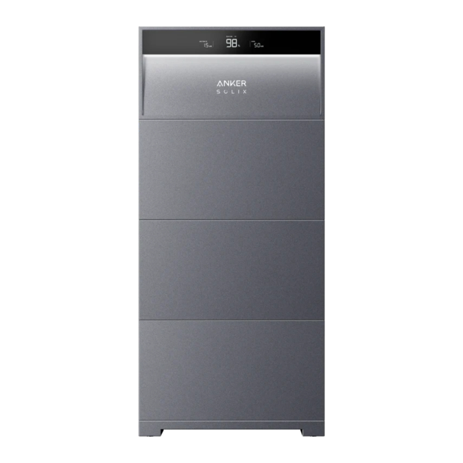
Product Appearance
Figure: Appearance of Anker SOLIX X1 Power Module X1-H(5~12)K-T.

- PV power ports (PV1+/PV1–, PV2+/PV2–)
- PV switch
- Toggle ON to power on the connected PV system.
- Toggle OFF to power off the connected PV system.
- BAT switch
- Toggle ON to power on the connected battery modules.
- Toggle OFF to power off the connected battery modules.
- Black start button
- To force a startup of the power module, press the black start button for 3 seconds.
- To force a shutdown of the power module, press the same button for 8 seconds.
- BMS port
- Internal ground point
- Screw hole for locking modules
- DC power ports (BAT+/BAT–)
- LED screen
- Status light
- WLAN/4G port
- Communication ports/terminals *
- AC grid port
- AC backup port
- Breather valve
- External ground point
- Screw hole for locking modules
- Heat sink
- Wall-mount cleats
Screen and Light Guide
LED Screen Guide
The LED screen of the power module will show you the working status of the system.

|  Overall Battery Level | |
 Recharging |  Discharging | |
|  Home Load Power | |
|  Connected to the Internet |  Disconnected from the Internet |
|  On Grid |  Off Grid |
|  Cumulative Solar Energy for the Day | |
Status Light Indication
The power module's light bar will indicate the system status.
 | Light Bar | Status |
| Flashing white once, and then steady white | Powered on | |
| Flashing white | Configuring or connecting to the Internet | |
| Steady white | On-Grid mode | |
| Steady blue | Off-Grid mode | |
| Flashing blue | Battery low in Off-Grid mode | |
| Flashing red | Malfunction | |
| Flashing white in sequence | Firmware upgrading |
Anker App for Smart Control
The Anker app enables remote control of your system with the following features:

- Remote access: Remotely power the system on/off, adjust electricity strategies, activate emergency backup power, and more.
- Real-time monitoring: Track current power usage, generation, and storage.
- Intuitive interface: Easily understand energy data by home scenes and topology.
- Instant alerts: Receive notifications of system issues for quick resolution.
Access Anker App (User)
- Download the Anker app from the App Store (iOS devices) or Google Play (Android devices), or by scanning the QR code.


- Log into the app. If you have not previously created an account, check the email to get your account name and initial password.
Check Energy Data
The home screen provides insight into your home's energy use and generation.
- Real-time energy flow:
Learn how the grid, solar system, and battery modules work together to power your home.
![]()
- Energy graphs over time:
View energy graphs by components of your energy system. The timescale can be set to day, week, month, or year.
![]()


Customize Work Mode
Work modes change the way your power module transfers power. Select your preferred work mode to meet your home's specific energy needs.

- Tap the settings icon in the top right corner of the home screen.
- Open the Modes menu.
- Choose one work mode from the following.
Self-Consumption Increase your home's reliance on solar power and reduce dependence on the grid. - When you produce enough solar power to offset your home's consumption and fully charge the battery modules, any excess solar power will export to the grid.
- When you consume more power than what's available from your solar system and stored in the battery modules, you will import power from the grid.
Time of Use The battery modules will charge when utility rates are the lowest, and power your home when utility rates are the highest. Make sure to edit your utility rate plan for weekdays and weekend. Off-Grid Power your home with solar power and the stored battery energy when the grid goes down.
* The Anker SOLIX X1's off-grid mode is incompatible with the Sunlight Backup mode of the Enphase microinverter. It is necessary to disable the Sunlight Backup mode of the Enphase microinverter before using the Anker SOLIX X1's off-grid mode. - Set backup reserve by adjusting the slider at the top of the screen.
- If you prefer to open more capacity for self-consumption mode or time-of-use mode, you can set a lower reserve percentage.
- If you prefer to reserve more energy for use during a grid outage, or if your area is more prone to outages, you can set a higher reserve percentage.
Set Advanced Options
There are three advanced options that impact how the energy storage system exports and imports power to and from the grid.

- Tap the settings icon in the top right corner of the home screen.
- Open the Modes menu.
- Scroll down to set the advanced options.
| Grid Charging | Turn on to allow the grid to charge battery modules. Turn off to charge the battery modules only from solar power. |
| Peak Shaving | Activate to smooth out peak loads and reduce overall charges on the grid. This is achieved by utilizing the stored battery energy. |
| Rapid Battery Charging | Charge the battery modules at full speed using both grid and solar power. |
Firmware Upgrade
To ensure your system can achieve optimal performance and use all the latest features, it is recommended to upgrade the firmware from time to time.
- Pay close attention to upgrade prompts from the app. Once you receive a notification, we encourage you to proceed with the manual upgradeimmediately to ensure your software is always up to date.
![]()
- If you want to check for firmware upgrade, go to Settings > Firmware Upgrade. If there's a new version, simply follow the on-screen instructions to complete the upgrade. You may choose Update Now or Select Update Time.
![]()


Maintenance
Power On/Off the System
To power on the system:
- Toggle the BAT switch of the power module to ON.
- Close the circuit breaker between the power module and the grid.
- Toggle the PV switch of the power module to ON.
To power off the system:
- Toggle the PV switch of the power module to OFF.
- Press the black start button of the power module for 8 seconds.
- Disconnect the circuit breaker between the power module and the grid.
- Toggle the BAT switch of the power module to OFF.
![warning]()
- After the system powers off, residual electricity and heat may still cause electric shocks and burns. Wait for at least 1 minute after powering off the system before performing any operations.
- Only qualified professionals or trained personnel are allowed to operate and maintain the equipment.
- To force a startup of the power module, press the black start button for 3 seconds. To force a shutdown of the power module, press the same button for 8 seconds.
Routine Maintenance
To ensure the energy storage system operates properly for an extended period, it is recommended to perform routine maintenance.
 Power off the system before cleaning it, connecting cables, and ensuring grounding reliability.
| Check Item | Check Method | Maintenance Interval |
| System cleanliness | Check periodically that the heat sinks are free from obstacles and dust. | Once every 6 to 12 months |
| System running status |
| Once every 6 months |
| Electrical connection |
| The first inspection is 6 months after the initial commissioning. From then on, the interval can be 6 to 12 months. |
| Grounding reliability | Check that ground cables are securely connected. | The first inspection is 6 months after the initial commissioning. From then on, the interval can be 6 to 12 months. |
| Firmware version | Check that the firmware is updated to the latest version via the app. | Once every 6 months |
Troubleshooting
Only qualified professionals or trained personnel are allowed to install, operate, and maintain the equipment.
You will receive push notifications from the Anker app once a system fault is detected. Please have the following information available when contacting Anker.
- Owner name
- Phone number or email address (the best way to contact you)
- Serial numbers
- Brief description of the issue
For instance, if a ground fault is detected, the Anker app will send a notification, the light bar will turn red, and the power module screen will show 'EE.' which meets the Earth Fault alarm requirements of AS/NZS 5033.
Emergency Handling
In the event of any threat to health or safety, always begin with these two steps before addressing the other suggestions below:
- Immediately contact the fire department or other relevant emergency response team.
- Notify all people who might be affected and ensure that they can evacuate the area.

Only perform the suggested actions below if it is safe to do so.
Fire
- Please shut down the equipment or disconnect the main power switch when it is safe.
- The high temperature may distort or damage the battery pack, resulting in electrolyte overflow or toxic gas leakage. Do not go near the battery pack and wear protective equipment.
- If the fire is small, use carbon dioxide or ABC dry powder extinguisher to extinguish the fire.
- If the fire is spreading, evacuate the building or equipment area immediately and call the fire department. Re-entry to burning buildings is prohibited.
- Do not touch or come into contact with high voltage components during fire fighting, due to the risk of electric shock.
- After extinguishing the fire, do not use the equipment, please contact your installer.
Flood
- Please shut down the equipment or disconnect the main power switch when it is safe.
- If the battery module is submerged, do not touch it to avoid the danger of electric shock.
- After the flood waters recede, do not use the equipment. Please contact your installer.
Battery Malfunction
- When the battery module has abnormal odor, electrolyte leakage, or heat, do not touch it, and contact professional personnel immediately.
- Professionals must wear protective equipment such as goggles, rubber gloves, gas masks, and protective clothing to protect themselves.
- The electrolyte is corrosive and contact may cause skin irritation or chemical burns. In case of accidental contact with the electrolyte, take the following measures immediately:
- Inhalation: Evacuate the contaminated area, keep fresh air circulating and seek immediate medical help.
- Eye contact: Flush eyes with plenty of water for at least 15 minutes. Do not rub eyes. Seek medical help immediately.
- Skin contact: Wash the contact area with plenty of soapy water and seek medical help immediately.
- Ingestion: Induce vomiting and seek medical help immediately.
- Do not continue to use abnormal battery modules, please contact your installer.
Battery Falling or Strong Impact
- If there is an obvious odor, smoke, or fire, keep away from the equipment immediately and contact professional personnel.
- Do not use the battery module if it has been dropped or hit. Please contact your installer.
In all cases, once the situation is stable, contact the Anker Customer Service.
Product Information
Nameplates


Specifications
Specifications are subject to change without notice.
| Product Name | Anker SOLIX X1 Power Module | |||
| Model Name | X1-H5K-T | X1-H8K-T | X1-H10K-T | X1-H12K-T |
| PV INPUT | ||||
| MPPT Voltage Range | 140 - 950 Vd.c. | 140 - 950 Vd.c. | 140 - 950 Vd.c. | 140 - 950 Vd.c. |
| Max. Input Voltage | 1000 Vd.c. | 1000 Vd.c. | 1000 Vd.c. | 1000 Vd.c. |
| Max. Input Current | 16/16 Ad.c. | 16/16 Ad.c. | 16/16 Ad.c. | 16/16 Ad.c. |
| Isc PV Array Short Circuit Current | 20/20 Ad.c. | 20/20 Ad.c. | 20/20 Ad.c. | 20/20 Ad.c. |
| Max. Inverter Backfeed Current to Array | 0 A | 0 A | 0 A | 0 A |
| BATTERY INPUT and OUTPUT | ||||
| Battery Type | Li-ion | Li-ion | Li-ion | Li-ion |
| Voltage Range | 350 - 450 Vd.c. | 350 - 450 Vd.c. | 350 - 450 Vd.c. | 350 - 450 Vd.c. |
| Rated Charge/Discharge Power | 5 kW/5 kW | 8 kW/8 kW | 10 kW/10 kW | 12 kW/12kW |
| Rated Charge/Discharge Current | 12.5 Ad.c./12.5 Ad.c. | 20 Ad.c./20 Ad.c. | 25 Ad.c./25 Ad.c. | 30 Ad.c./30 Ad.c. |
| Max. Continue Charge/Discharge Current | 15 Ad.c./15 Ad.c. | 24 Ad.c./24 Ad.c. | 30 Ad.c./30 Ad.c. | 36 Ad.c./36 Ad.c. |
| AC GRID INPUT and OUTPUT | ||||
| Rated Voltage | 220/380 Va.c., 230/400 Va.c., 3L+N+PE | 220/380 Va.c., 230/400 Va.c., 3L+N+PE | 220/380 Va.c., 230/400 Va.c., 3L+N+PE | 220/380 Va.c., 230/400 Va.c., 3L+N+PE |
| Rated Frequency | 50/60 Hz | 50/60 Hz | 50/60 Hz | 50/60 Hz |
| Rated Output Active Power | 5 kW | 8 kW | 10 kW | 12 kW |
| Rated Output Apparent Power | 5 kVA | 8 kVA | 10 kVA | 12 kVA |
| Max. Output Active Power | 5 kW | 8 kW | 10 kW | 12 kW |
| Max. Output Current | 8.4 Aa.c. | 13.3 Aa.c. | 16.7 Aa.c. | 20 Aa.c. |
| Max. Input Power/Current From Grid | 10 kVA/15.2 Aa.c. | 16 kVA/24.3 Aa.c. | 20 kVA/30.3 Aa.c. | 20 kVA/30.3 Aa.c. |
| Power Factor Range | 0.8 ind - 0.8 cap | 0.8 ind - 0.8 cap | 0.8 ind - 0.8 cap | 0.8 ind - 0.8 cap |
| Current (Inrush) | 100 A/20 us | 100 A/20 us | 100 A/20 us | 100 A/20 us |
| Max. Output Fault Current | 68 A/260 us | 68 A/260 us | 68 A/260 us | 68 A/260 us |
| Max. Output Overcurrent Protection | 30 A/10 s | 30 A/10 s | 30 A/10 s | 30 A/10 s |
| AC BACKUP OUTPUT | ||||
| Rated Output Power | 5 kW | 8 kW | 10 kW | 12 kW |
| Rated Output Apparent Power | 5 kVA | 8 kVA | 10 kVA | 12 kVA |
| Max. Output Power | 5.25 kW | 8.4 kW | 10.5 kW | 12.6 kW |
| Max. Output Apparent Power | 5.25 kVA | 8.4 kVA | 10.5 kVA | 12.6 kVA |
| Max. Output Current | 7.2 Aa.c. | 11.6 Aa.c. | 14.5 Aa.c. | 17.4 Aa.c. |
| Output Voltage | 220/380 Va.c., 230/400 Va.c., 3L+N+PE | 220/380 Va.c., 230/400 Va.c., 3L+N+PE | 220/380 Va.c., 230/400 Va.c., 3L+N+PE | 220/380 Va.c., 230/400 Va.c., 3L+N+PE |
| Output Frequency | 50/60Hz | 50/60Hz | 50/60Hz | 50/60Hz |
| Power Factor Range | 0.8 ind - 0.8 cap | 0.8 ind - 0.8 cap | 0.8 ind - 0.8 cap | 0.8 ind - 0.8 cap |
| GENERAL INFORMATION | ||||
| Inverter Topology | Non-Isolated | Non-Isolated | Non-Isolated | Non-Isolated |
| Overvoltage Category | III[MAINS], II[PV, BAT] | III[MAINS], II[PV, BAT] | III[MAINS], II[PV, BAT] | III[MAINS], II[PV, BAT] |
| Operating Temperature Range | -25°C to 60°C | -25°C to 60°C | -25°C to 60°C | -25°C to 60°C |
| Storage Temperature Range | -40°C to 70°C | -40°C to 70°C | -40°C to 70°C | -40°C to 70°C |
| Relative Humidity | 5% to 95% | 5% to 95% | 5% to 95% | 5% to 95% |
| Altitude | ≤ 4000 m | ≤ 4000 m | ≤ 4000 m | ≤ 4000 m |
| Ingress Protection | IP66 | IP66 | IP66 | IP66 |
| Protection Class | I | I | I | I |
| Active Anti-Islanding Method | Power Variation (method c) | Power Variation (method c) | Power Variation (method c) | Power Variation (method c) |
Note: When applying AS/NZS 4777.2:2020, the rated voltage is 230 Va.c., the rated frequency is 50 Hz, and the power factor range is 0.8 inductive (under-excited) to 0.8 capacitive (over-excited).
Safety Information
IMPORTANT SAFETY INSTRUCTIONS
Symbols
| Symbol | Description |
 | Caution Indicates a low-risk hazard. Failure to avoid this hazard could result in minor or moderate injury. |
 | Warning Indicates a hazard with a moderate level of risk. Failure to avoid this hazard could result in death or serious injury. |
| Danger Indicates a highly risky hazard. Failure to avoid this hazard could result in death or serious injury. |
 | Refer to Operating Instructions Indicates that users should refer to operating or installation instructions before proceeding. |
  | Caution, risk of electric shock, energy storage timed discharge Indicates discharge time is 1 minute from de-energization. |
| Risk of electric shock Indicates components that present risk of electrical shock. |
 | Caution, hot surface Indicates that equipment surfaces may be hot and pose a burn risk. |
 | PE conductor terminal Indicates a terminal that allows the electrical connection of conductors for earthing or grounding purposes. |
General Information
This document contains important instructions that must be followed during installation, use, and maintenance.
Read instructions carefully before performing any operation on the equipment.
Do not make any changes or create settings that are not described in this document. If physical injury, loss of data, or damage is caused by failure to follow instructions, the warranty does not apply.
Battery Safety
General Instructions Regarding Removal and Installation of Batteries:
- When replacing batteries, replace with the same type and number of batteries.
- Do not dispose of batteries in a fire. The batteries may explode.
- Do not open or damage batteries. Released electrolytes may be toxic and are harmful to skin and eyes.
- A battery can present a risk of electrical shock and high short-circuit current. The following precautions should be observed when working on batteries:
- Remove watches, rings, or other metal objects.
- Use tools with insulated handles.
- Wear rubber gloves and boots.
- Do not lay tools or metal parts on top of batteries.
- Disconnect the charging source prior to connecting or disconnecting battery terminals.
- Determine if the battery is inadvertently grounded. If inadvertently grounded, remove the source from the ground. Contact with any part of a grounded battery can result in electrical shock. The likelihood of such shock can be reduced if such grounds are removed during installation and maintenance (applicable to equipment and remote battery supplies not having a grounded supply circuit).

A BATTERY CAN PRESENT A RISK OF ELECTRICAL SHOCK, BURN FROM HIGH SHORT-CIRCUIT CURRENT, FIRE, OR EXPLOSION FROM VENTED GASES. OBSERVE PROPER PRECAUTIONS.
WHEN REPLACING BATTERIES, USE THE SAME NUMBER AND THE FOLLOWING TYPE OF BATTERIES: LiFePO4.
PROPER DISPOSAL OF BATTERIES IS REQUIRED. REFER TO YOUR LOCAL CODES FOR DISPOSAL REQUIREMENTS.
- Replacing a battery with an incorrect type may nullify safeguards and create danger;
- Disposal of the battery/equipment in a fire or another source of significant heat, or by mechanically crushing or cutting the battery/equipment may result in an explosion;
- Leaving the battery/equipment in an extremely hot environment may result in an explosion or leakage of flammable liquids or gases;
- Subjecting the battery/equipment to extremely low air pressure may result in an explosion or leakage of flammable liquids or gases.
Personal Safety
To reduce the risk of burns, do not touch the equipment surfaces as they may be hot.
Never touch the enclosure of operating equipment.
- Ensure that power is off during installation. Do not install or remove a cable with the power on.
- Non-standard and improper operations on the energized equipment may cause fire, electric shocks, or explosion, resulting in property damage, personal injury, or even death.
- Before operations, remove conductive objects such as watches, bracelets, bangles, rings, and necklaces to prevent electric shocks.
- During operations, use dedicated insulated tools to prevent electric shocks or short circuits.
- Do not make contact with other conductors, or indirect contact with power supply equipment through damp objects.
- Do not power on the equipment until it has been installed or confirmed by a professional.
- Only qualified professionals or trained personnel are allowed to install, operate, and maintain the equipment.
- If there is a probability of personal injury or equipment damage during operations on the equipment, immediately stop the operation, report the case to the supervisor, and take feasible protective measures.
- Do not touch the energized equipment, as the enclosure may be hot.
Electrical Safety
Do not disconnect under load!
Use conductors with insulation rated for at least 90 ℃/194℉.
Do not wire when energized.
Risk of electric shock. Terminals on the line and load sides may be energized when circuit breakers are in the open position.

Risk of electric shock from stored energy. Start maintaining the equipment at least 1 minute after the equipment disconnects from all external power supplies.
- Before installation, ensure that the equipment is intact. Otherwise, electric shocks or fires may occur.
- Non-standard and improper operations may result in fire or electric shocks.
- Prevent foreign matter from entering the equipment during operations.
- Do not route cables behind the air intake and exhaust vents of the equipment.
- For the equipment that needs to be grounded, install the ground cables first when installing the equipment and remove the ground cables last when removing the equipment.
- Before installing or removing power cables, the equipment and its switches must be disconnected.
- Do not damage the grounding conductors.
- The equipment terminals are used for electrical connections only.
- Ensure that the power module is connected to external breakers for the AC output circuit and the battery circuit.
- Ensure that all electrical connections comply with local electrical standards.
- Obtain approval from the local electric utility company before using the equipment in grid-tied mode.
- Ensure that the cables you prepared meet local regulations.
- The maximum operating temperature for the included cables is 221 ℉/105°C.
- Use dedicated insulated tools when performing high-voltage operations.
- Before making electrical connections, switch off the disconnector on the upstream device to cut off the power supply if people may come into contact with energized components.
- Before connecting a power cable, check that the label on the power cable is correct.
- If the equipment has multiple inputs, disconnect all the inputs before operating the equipment.
Environmental Requirements
- Do not expose the equipment to flammable or explosive gas or smoke. Do not perform any operation on the equipment in such environments.
- Do not store any flammable or explosive materials near the equipment.
- Install the equipment in an area far away from liquids and in a well ventilated environment.
- To prevent fire due to high temperature, ensure that the ventilation vents or heat dissipation system are not blocked when the equipment is running.
Mechanical Safety
- Do not drill holes into the equipment.
- Wear goggles and protective gloves when drilling holes.
- When moving the equipment by hand, wear protective gloves to prevent injuries.
- Clean up any debris that may have accumulated within or around the equipment after drilling.
- Be cautious to avoid injury when moving heavy objects.
Commissioning
- When the equipment is powered on for the first time, ensure that professional personnel set parameters correctly. Incorrect settings may result in inconsistency with local certification and affect the normal operation of the equipment.
Maintenance and Replacement
Disconnect all sources of supply before servicing.
Replace only with the same ratings and type of a fuse.
Disconnect supply before changing a fuse.
Only certified professionals are allowed to install and maintain the battery and external power supplies. High touch current, earth connection essential before connecting supply.

Do not disassemble the equipment without authorization. Tampering with the equipment will invalidate the warranty.
- High voltage generated by the equipment during operation may cause an electric shock, which could result in death, serious injury, or serious property damage.
- Prior to maintenance, power off the equipment and strictly comply with the safety precautions in this document and relevant documents.
- After powering off the equipment, wait at least 6 minutes before disassembling any cables or components.
- Maintain the equipment with proper tools, testing equipment, and sufficient knowledge of this document.
- Turn off the equipment switches when maintaining the electric devices or power distribution devices connected to the equipment.
- Place temporary warning signs or erect fences to prevent unauthorized access to the maintenance site.
- If the equipment is faulty, contact your supplier.
- The equipment can be powered on only after all faults are rectified. Failing to do so may escalate faults or damage the equipment.
Customer Service
support@anker.com
(UK) +44 (0) 1616 056 301
(DE) +49 (800) 000 2522
(AU) +61 1800 929 112
(IT) +39 800 776 561
10-Year Limited Warranty
Please visit ankersolix.com/warranty for full warranty details.
Documents / Resources
References
Download manual
Here you can download full pdf version of manual, it may contain additional safety instructions, warranty information, FCC rules, etc.
Advertisement


Need help?
Do you have a question about the SOLIX X1 and is the answer not in the manual?
Questions and answers