Universal Audio Apollo x16D, Apollo X Series Manual
- Hardware manual (35 pages)
Advertisement
- 1 Introduction
- 2 Front Panel
- 3 Rear Panel
- 4 Interconnections
- 5 Software Setup
- 6 Specifications
- 7 Hardware Block Diagram
-
8
Troubleshooting
- 8.1 Unit won't power on
- 8.2 No monitor output
- 8.3 Input/output levels are too high or too low
- 8.4 Can't fine tune signal I/O levels
- 8.5 Network audio channels unavailable
- 8.6 Audio glitches and/or dropouts during playback
- 8.7 Undesirable echo/phasing
- 8.8 HOST indicator is unlit or red
- 8.9 Various LEDs inside the unit are blinking
- 8.10 Apollo x16D is behaving unexpectedly
- 9 Notices
- 10 Technical Support
- 11 Documents / Resources
Introduction
Perfect for live sound venues or networked recording studios, Apollo x16D gives you elite-class Apollo X sound and realtime UAD plug-in processing over Thunderbolt and Dante.
With Apollo x16D, you can mix and record live performances with over 200 UAD plug-ins from Neve, SSL, and Auto-Tune, plus classic LA-2A and 1176 compressors, and more.
Take Elite-Class Apollo Sound on Stage
We built Apollo x16D for both live sound engineers and networked recording studios. With its 16 channels of Dante I/O, elite-class audio conversion, and HEXA core DSP processing — the world's most powerful system for running UAD plug-ins in realtime — Apollo x16D seamlessly connects to your digital mixing console, putting over 200 UAD plug-ins right at your fingertips.
Work Fast & Never Lose Your Settings
With its powerful digital mixing engine giving you control over inputs, outputs, and plugin routing — Apollo x16D makes it easy to quickly build your mix and control entire effects chains in realtime. Then quickly recall your plug-in settings over MIDI, all without interrupting the performance.
Add Hundreds of Effects to a Single Rack Space
Apollo x16D comes in two editions, both delivering a generous suite of UAD plug-ins right out of the box. Build your mix with classic Teletronix LA-2A and 1176 compressors, Pultec EQs, and Neve channel strips to modern favorites from Auto-Tune, Avalon, and more.*
Expand Your Studio Over Dante
Link up to four x16Ds to build a 64-channel Dante system with network redundancy. Or expand your current Thunderbolt Apollo system over Dante — the most low-latency and scalable audio network available. This means that if you've been considering making the switch to a networked recording studio, or you simply want to grow to a multi-room setup, you don't have to start from scratch.
Mix Down to Surround
After the show, bring Apollo x16D back to the studio, where it becomes your all-in-one monitoring hub for mixing formats up to 9.1.6. This allows you to easily create 16-channel immersive audio mixes of live sets or studio recordings for Dolby Atmos, Auro-3D, Sony 360 Reality Audio, and others.
Apollo x16D Features
Key Features
- 18 x 20 audio interface featuring Dante I/O (supports AES67 mode @ 48 kHz)
- 24-bit / 192 kHz elite-class Apollo X D/A conversion
- Stereo AES I/O for connection to professional digital outboard hardware
- Includes up to 100+ UAD plug-ins with Ultimate+ or Essentials+ editions
- Recall plug-in settings over MIDI, even in the middle of a performance
- Onboard HEXA Core Processing for mixing with UAD plug-ins at near-zero latency
- Compatible with Thunderbolt Apollo interfaces to expand systems over Dante*
- Create 16-channel immersive audio mixes for Dolby Atmos, Auro-3D, Sony 360 Reality Audio, and others
- ALT monitoring support in all monitor modes (2 x ALT mon for stereo, 1 x ALT mon for all)
- Free industry-leading technical support from knowledgeable audio engineers
Audio Interface
- 16 x 16 simultaneous network audio input/output channels via Dante or AES67
- Stereo analog monitor outputs via dual XLR connectors
- Front panel pre-fader metering of network signal input or output levels
- Two Thunderbolt 3 ports for daisy-chaining other Thunderbolt devices
Monitoring
- Independently-addressable stereo monitor outputs
- Front panel control of monitor levels and muting
- Front panel pre-fader metering of monitor bus levels
- Selectable reference level for monitor outputs (+4 dBu or -10 dBV)
- Digital AES/EBU outputs can mirror the analog monitor outputs
UAD-2 HEXA Inside
- Six SHARC® DSP processors
- Realtime UAD Processing on all of Apollo x16D's inputs
- Same features and functionality as other UAD-2 products when used with DAW
- Can be combined with other UAD-2 devices for increased mixing DSP
- Get UAD Powered Plug-Ins at the UA online store
Software
UAD Console application
- Analog-style control interface for realtime monitoring and tracking
- Enables Realtime UAD Processing with UAD-2 plug-ins
- Remote control of Apollo x16D features and functionality
- Plug-In Scenes for seamless audio processing transitions via MIDI
UAD Console Recall plug-in
- Saves UAD Console configurations inside DAW sessions for easy recall
- Convenient access to UAD Console's monitor controls via DAW plug-in
- VST3, AAX 64, and Audio Units plug-in formats
UAD Meter & Control Panel application
- Configures global UAD settings and monitors system usage
Other
- Easy firmware updates
- 1U rack-mountable form factor
- One year warranty includes parts and labor
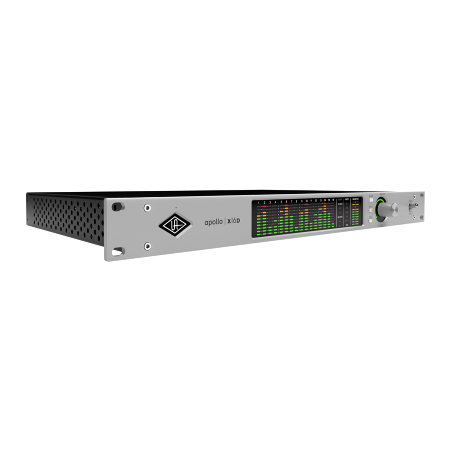
Front Panel
This section describes the features and functionality of all controls and visual elements on the Apollo x16D front panel.
Tip: All front panel functions except METER and POWER can be controlled remotely with the included UAD Console software application. Changes made with the front panel controls are mirrored in UAD Console, and vice versa.

- Power Indicator (UA Logo)
The Universal Audio logo illuminates when the external power supply is properly connected to the AC outlet and the power input on the rear of the unit, and the Power switch (#13) is in the up position. - Talkback Microphone
The built-in talkback mic is located inside of this hole. Power indicator and The talkback function is configured and operated in UAD talkback microphone Console.
![]()
The talkback microphone is sensitive. To avoid equipment damage, do not insert any object into the mic hole, apply pressurized air into the mic hole, or use a vacuum over the mic hole.


Main Apollo x16D front panel elements
- Channel Level Meters
The 10-segment LED channel meters display the input or output signal peak levels for network channels 1 – 16. Input or output metering is selected with the METER switch (#9), and the input/output state is shown by the METER indicators (#6).
The dB values of the meter LEDs are indicated between the meters for channels 4 & 5, 8 & 9, and 12 & 13. "0" indicates a level of 0 dBFS. When digital clipping occurs (when 0 dBFS is exceeded), the red "C" (clip) LED illuminates.
Input Channel Meters
When set to INPUT, the channel meters display the signal peak input levels for network channels 1 – 16.
Output Channel Meters
When set to OUTPUT, the channel meters display the signal peak output levels for network channels 1 – 16. - HOST Indicator
The HOST indicator displays the status of the Thunderbolt connection to the host computer system. The possible states are:
Lit – The unit is communicating with the host computer and operating normally.
Unlit – The unit is starting up or it is not recognized by the host computer. Verify software installation and Thunderbolt connections.
Red – System error. Please contact UA customer care if the issue persists. - CLOCK Indicators
The clock source and status are displayed with these indicators. Either internal (INT) or external (EXT) is displayed. The clock source is set within the UAD Console application; see the Apollo Software Manual for details.
Internal Clock
When set to internal clock, the INT indicator is illuminated white.
External Clock
Apollo x16D can use an external digital clock source from the Word Clock, AES/EBU, or network inputs. The EXT indicator has two possible states:
White – When set to external clock and a valid clock signal is detected at the specified port, the EXT indicator is illuminated white and Apollo x16D is synchronized to the external clock source.
Red – When set to external clock and a valid clock signal is NOT detected at the specified port, the EXT indicator is illuminated red and the internal clock remains active instead. In this situation, if/when the specified external clock becomes available, Apollo x16D switches back to the external clock, and the EXT indicator is illuminated and white.
![]()
When set to use any external clock source, Apollo x16D's sample rate must be manually set to match the sample rate of the external clock. - METER Indicators
These indicators show the current state of the Channel Level Meters (#3). The current state is changed with the METER switch (#9).
IN – When IN is illuminated, the channel meters display network input signal levels. OUT – When OUT is illuminated, the channel meters display network output signals levels. - Sample Rate Indicators
These indicators display the current system sample rate setting. The sample rate is set within the UAD Console application or the host DAW; see the Apollo Software Manual for details. - Monitor Output Level Meters
The 10-segment LED meters display the signal peak output levels of the rear panel Left & Right Monitor outputs at the output of the D/A converters. These meters are before the Monitor Level control (pre-fader) and reflect the D/A converter levels regardless of the current Monitor Level and Headphone Level knob settings.
The dB values of the monitor meter LEDs are indicated between the left and right channel meters. When digital clipping occurs, the red "C" (clip) LED illuminates.
If the monitor output level clips, reduce the monitor output level within the DAW and/or reduce the output level of individual channels feeding the monitor output bus within the UAD Console application. - Meter Switch
This switch determines whether the Channel Level Meters (#3) are displaying input levels or output signal levels. Pressing the switch toggles the state of the meters and the Meter Indicators (#6). - FCN Switches
Note: When more than one Apollo interface is connected in a multi-unit configuration, the FCN switch is operable on the designated monitor unit only.
FCN 1 and FCN 2 are assignable switches that can be configured to control monitoring functions. The function of each switch is configured with the FCN SWITCH ASSIGN menus in the Hardware panel within UAD Console Settings.
The LED within each switch flashes (FCN 1 orange, FCN 2 yellow) when its monitoring function is active. The function is toggled with the switch is pressed again. The available functions are listed below.
ALT 1, ALT 2
Apollo x16D features ALT (alternate) monitoring capabilities. ALT monitoring can be used to control up to two alternate pairs of monitor speakers. ALT monitoring is enabled in the Hardware panel within UAD Console Settings by increasing the ALT COUNT setting to a non-zero value.
For complete details about how to configure and use the ALT monitoring features, refer to the Apollo Software Manual.
MONO
Sums the left and right channels of the stereo monitor mix into a monophonic signal.
The Monitor Level Indicator ring (#12) flashes when MONO is active.
DIM
Attenuates the signal level at the monitor outputs by the dB amount set in the CONTROL ROOM strip within the UAD Console application. The Monitor Level Indicator ring (#12) flashes when DIM is active.
TALKBACK
Activates the talkback mic and the DIM function. Talkback is active when the button is lit. Press and release the button quickly to latch talkback ON. To momentarily activate the function and deactivate when the button is released, press for longer than 0.5 seconds. The Monitor Level Indicator ring (#12) flashes when talkback is active. - Monitor Level & Mute Knob
This rotary encoder serves two functions. Rotating the knob adjusts the monitor output level, and pressing the knob mutes the monitor outputs.
Monitor Level
Rotating the knob clockwise increases the signal level at the Left & Right Monitor Outputs on the rear panel. If ALT monitor outputs are configured and active, this knob controls the signal level at the ALT monitoring line outputs.
Monitor Mute
Pressing the Monitor knob toggles the mute state of the signals at the Left & Right Monitor Outputs on the rear panel. If ALT monitoring is configured in the Hardware panel within UAD Console Settings (when ALT COUNT is a non-zero value), the ALT monitor outputs are also muted by this control.
When the monitor outs are muted, the Monitor Level Indicator ring (#12) is red. - Monitor Level & Monitor State Indicator
Tip: The Monitor Level and Monitor State indications are reflected in the Monitor column within the UAD Console application.
Monitor Output Level Indicator
The relative signal level at the rear panel monitor outputs (and ALT monitor outputs, if configured) is indicated by the illuminated ring surrounding the Monitor Level knob.
This indicator is after the Monitor Level control (post fader). The ring indicates relative gain levels and is not calibrated to indicate any specific dB value.
Tip: Precise numerical dB gain values for the Monitor Level Knob are displayed within the UAD Console application.
Monitor State Indicator
The color of the indicator ring indicates the current state of the monitor outputs:
Green – The main monitor outputs are active with variable level control.
Red – The main monitor outputs (and ALT monitor outputs, if configured) are muted.
Orange – The ALT 1 monitor outputs are active.
Yellow – The ALT 2 monitor outputs are active.
Flashing – The monitor DIM, MONO, and/or TALKBACK functions are active. - Power Switch
This switch applies power to Apollo x16D. When the unit is powered on, the Universal Audio logo (#1) is illuminated. The external power supply must be properly connected for this switch to function.
![]()


Rear Panel

- Power Input
The included external power supply connects to this 4-pin locking XLR jack. Apollo x16D requires 12 volts DC power and draws a maximum of 72 watts (30 watts typical).
To eliminate risk of circuit damage, connect only the factory-supplied power supply. Use the Power switch on the front panel to power the unit on and off.
![]()
Do not disconnect the power supply while Apollo x16D is in use, and confirm the Power switch is in the "off" position before connecting or disconnecting the power supply. - Thunderbolt 3 Ports
Apollo x16D has two Thunderbolt 3 ports. One port is used to connect Apollo x16D to a Thunderbolt 3 port on the host computer. Thunderbolt 3 peripheral devices may be serially connected (daisy-chained) to the second Thunderbolt 3 port.
When Apollo x16D is properly communicating with the host computer via Thunderbolt, the HOST indicator (#4) illuminates.
Note: Apollo x16D can be used with Thunderbolt 1 and Thunderbolt 2 ports on Apple Mac computers via the Apple Thunderbolt 3 to Thunderbolt 2 Adapter. Connections to Thunderbolt 1 or Thunderbolt 2 ports on Windows PCs are not supported.
Thunderbolt Bus Power
Per the Thunderbolt specification, bus power is supplied to downstream (daisy-chained) Thunderbolt peripheral devices. Apollo x16D must be powered on for the daisy-chained peripheral to receive Thunderbolt bus power. - 75 Ohm Word Clock Termination Switch
This switch provides internal 75-ohm word clock input signal termination when required. Word clock termination is active when the switch is engaged (depressed).
Apollo x16D's termination switch should only be engaged when Apollo x16D is set to sync to external word clock and it is the last device at the receiving end of a word clock cable. For example, if Apollo x16D is the last "follow" unit at the end of a clock chain (when Apollo x16D's word clock OUT port is not used), termination should be active. - Word Clock I/O
Word Clock In
Apollo x16D's internal clock can be synchronized (followed) to an external leader word clock. This is accomplished by setting Apollo x16D's clock source to Word Clock within the UAD Console application, connecting the external word clock's BNC connector to Apollo x16D's word clock input, and setting the external device to transmit word clock. If Apollo x16D is the last device in the clock chain, the Termination switch (#16) should be engaged.
![]()
Apollo x16D's sample rate must be manually set to match the incoming clock's sample rate.
Note: Apollo x16D can be synchronized to an external "1x" clock signal only. Superclock, overclocking, and subclocking are not supported.
Word Clock Out
This BNC connector transmits a standard (1x) word clock when Apollo x16D is set to use its internal clock. The clock rate sent by this port matches the current system sample rate, as specified within the UAD Console application.
When Apollo x16D is set to use external word clock as its clock, Apollo x16D is a word clock follow. If the incoming external word clock is within ±4% of a supported sample rate (44.1 kHz, 48 kHz, 88.2 kHz, 96 kHz, 176.4 kHz, 192 kHz), Word Clock Out will mirror Word Clock In with a slight phase delay (about 40 ns).
Because Apollo x16D's word clock output is not a true mirror of the word clock input, word clock out should not be used to daisy chain the word clock if Apollo x16D is in the middle of the word clock chain. The correct method to connect Apollo x16D in the middle of a word clock chain is to use a T-connector at Apollo x16D's word clock input and leave Apollo x16D's word clock output unconnected. In this configuration, the Termination switch should not be engaged. - AES/EBU Ports
The AES/EBU ports provide two channels of digital I/O with resolutions up to 24-bit at 192 kHz via XLR connectors. For optimum results, use only high-quality 110-ohm XLR cables specifically designed for AES/EBU digital audio.
SR Convert
Sample rate conversion can be enabled on the AES/EBU input. This function is set in the AES/EBU input channel strip(s) within the UAD Console application. When sample rate conversion is enabled and the sample rate of the incoming AES/EBU signal does not match the sample rate specified in the UAD Console application, the AES/EBU signal is converted to match Apollo x16D's sample rate.
Note: When Apollo x16D is set to use AES/EBU as the leader clock source, sample rate conversion is inactive.
Mirror Monitor Outputs
The AES/EBU output can be configured to mirror the Monitor outputs, for routing the stereo Monitor signal to the stereo AES/EBU input of other devices. This feature is set with the DIGITAL MIRROR menu in the Hardware panel within UAD Console Settings.

- Left & Right Monitor Outputs
These balanced XLR jacks are line-level analog outputs typically used for connection to a stereo loudspeaker monitoring system. The signal levels at these outputs are controlled with the Monitor Level & Mute knob (#11). The Monitor Outputs are DC coupled.
The Monitor Outputs can be configured to use an operating level of +4 dBu (default value) or -10 dBV. This option is set in the Hardware panel within UAD Console Settings.
The Monitor Outputs are completely independent from the 16 network outputs (except when ALT monitoring is configured). By default, these outputs are labeled MON L and MON R in Apollo's device drivers. In the DAW, the "1–2" or "L–R" or "Main" outputs are routed to these outputs (these labels vary within each particular DAW).
Tip: The AES/EBU output (#18) can be configured to mirror the Monitor Outputs, for routing the stereo monitor signal to the stereo AES/EBU input of other devices. This feature is set with the DIGITAL MIRROR menu in the Hardware panel within UAD Console Settings.
Network Audio I/O PortsConnect Apollo x16D to other Dante or AES67 equipment with these 1 Gigabit Ethernet ports. If using only one port, connect to the Primary port.
Interconnections
Installation Notes
- Apollo x16D may get hot during normal operation if it doesn't receive adequate airflow circulation around its chassis vents. When mounting Apollo x16D in a rack, leaving at least one empty rack space above the unit to allow adequate airflow for cooling is recommended.
- If Apollo x16D is installed near other heat generating equipment, external cooling (such as a fan) may be needed to keep the ambient temperature below 104º F (40º C).
- As with any sound system, the following steps are recommended to avoid audio spikes in your speakers and headphones:
- Apply power to the speakers last, after all other devices (including Apollo x16D) are powered on.
- Turn off the speakers first, before all other devices (including Apollo x16D) are powered off.
- Remove headphones from ears before powering Apollo x16D on or off.
Apollo x16D Connections
Apollo x16D requires two connections to your host computer:
A Thunderbolt connection – Your Apollo x16D(s) must be connected via Thunderbolt to your computer. Apollo devices, including Apollo x16Ds, can be daisy-chained to the host computer in any order.
Note: The Apollo daisy chain must be connected to only one Thunderbolt port on the host computer.
An Ethernet network connection – Your Apollo x16D must be connected from one of the network ports via an Ethernet cable to your computer, either directly, or through a Dantecapable Ethernet switch. You might need an Ethernet adapter for the host computer connection.
Network Modes
Apollo x16D networked audio can be operated in Switched mode or Redundant mode. This operating mode is set in the Dante Controller software. Use of these modes changes the operation of the Ethernet ports. Consider Redundant Mode when you require real-time failover capabilities. Refer to the Networked Audio article in the for more information.
Apollo Expanded
When more I/O and/or DSP is needed, up to four Apollo interfaces and six UAD devices total can be cascaded together via Thunderbolt in a multiple-unit configuration. For complete details about multi-unit cascading.
Thunderbolt Notes
- Apollo x16D must be connected via a Thunderbolt 3 cable (not included) to computers that have Thunderbolt 3 ports.*
- Although Thunderbolt 3 always uses USB-C connectors, not all USB-C ports are Thunderbolt 3 ports. Similarly, not all USB-C cables are Thunderbolt 3 cables. Always connect Apollo x16D to a Thunderbolt 3 port with a Thunderbolt 3 cable.
- Connect only one Thunderbolt 3 cable between Apollo x16D and the host computer. Thunderbolt is a bidirectional protocol.
- Apollo x16D cannot be bus powered via Thunderbolt. The included external power supply must be used.
- Thunderbolt bus power is supplied to downstream (daisy-chained) peripheral devices. Apollo x16D must be powered on for the daisy-chained peripheral to receive Thunderbolt bus power.
*Note: With Mac computers only, Apollo x16D can be connected to Thunderbolt 1 and Thunderbolt 2 computer ports via the Apple Thunderbolt 3 to Thunderbolt 2 adapter. Visit help.uaudio.com for details.
Apollo x16D Configuration and Operation
For typical setup example diagrams, configuration instructions, and software operation, refer to the Networked Audio article.
Software Setup
Note: Items on this page are detailed in the Apollo Software Manual.
System Requirements
All system requirements must be met for Apollo x16D to operate properly. Before proceeding with installation, see the system requirements in the Apollo Software Manual.
Software Installation
The software must be installed to use the hardware and UAD plug-ins. The UAD software installer contains the Apollo x16D software, drivers, and UAD plug-ins.
Registration and Authorization
Apollo x16D must be registered and authorized to unlock UAD plug-ins that are bundled with the product. To register and authorize Apollo x16D, visit:
- www.uaudio.com/apollo/start
Note: For optimum results, connect and power on Apollo x16D before installing the software.
Latest Software
To obtain the latest UAD installer after initial registration, use the UA Connect application. If you don't already have UA Connect, get it at:
System Configuration
Complete details about setting up the Apollo x16D system, including how to integrate with a DAW and related information, are included in the Apollo Software Manual.
UAD Console Application
The included UAD Console application is the software interface for the Apollo x16D hardware. UAD Console controls Apollo and its digital mixing, monitoring, and Realtime UAD Processing features. UAD Console is also used to configure Apollo x16D I/O settings such as sample rate, clock source, reference levels, and more.
UA Support Videos
Informational videos are available to help you get started with Apollo x16D:
- help.uaudio.com
Specifications
All specifications are typical performance unless otherwise noted. Tested with the Audio Precision APx555 Audio Analyzer under the following conditions: 48 kHz internal sample rate, 24-bit sample depth, 20 kHz measurement bandwidth, +24 dBu headroom, balanced output, and internal clock.
Specifications are subject to change without notice.
| SYSTEM | |
| I/O Complement | |
| Network Audio Ports (1 Gbps Ethernet) | Two |
| Network Audio Channels | 16 inputs, 16 outputs |
| Analog Monitor Outputs (DC coupled) | Two (one stereo pair) |
| AES/EBU | One stereo input, one stereo output |
| Thunderbolt 3 Ports | Two |
| Word Clock | One input, one output |
| Talkback Mic (built-in) | One |
| Conversion | |
| A/D conversion | 1 channel (Talkback mic) |
| D/A conversion | 2 channels (stereo monitor outputs) |
| Supported Sample Rates (kHz) | 44.1, 48, 88.2, 96, 176.4, 192 |
| Bit Depth Per Sample | 24 |
| Dante to Dante Round-Trip Latency (excluding Dante and plug-in latency) | 0.8 ms @ 96 kHz |
| Dante to Monitor Round-Trip Latency (excluding Dante and plug-in latency) | 1.0 ms @ 96 kHz |
| ANALOG I/O | |||
| Monitor Outputs 1 – 2 | |||
| Frequency Response | 20 Hz – 20 kHz, ±0.02 dB | ||
| Dynamic Range | 133 dB (A–weighted) | ||
| Total Harmonic Distortion + Noise Ratio (1 kHz @ -1 dBFS) | -129 dB (0.000037%) | ||
| Maximum Output Level (Reference Level @ +4 dBu) | 24 dBu (21.8 dBV) | ||
| Maximum Output Level (Reference Level @ -10 dBV) | 10 dBV (12.2 dBu) | ||
| Output Impedance | 100 Ohms | ||
| Connector Type | Balanced Male XLR (pin 2 hot) | ||
| DIGITAL I/O | |||
| Network Audio | |||
| Connector Type | RJ45 | ||
| Format | Dante, AES67 (selectable) | ||
| AES/EBU | |||
| Connector Type | XLR | ||
| Format | IEC 60958 Type I | ||
| Word Clock | |||
| Connector Type | BNC | ||
| Lock Range | ±4% of any supported sample rate | ||
| Word Clock Input Termination | 75 Ohms, switchable | ||
| Synchronization Sources | |||
| Internal, Word Clock, AES/EBU, Dante | |||
| ELECTRICAL | |
| Power Supply | External AC-to-DC Power Supply, Level VI compliant |
| AC Input Connector Type | IEC Male |
| AC Requirements | 100V – 240V AC, 50 – 60 Hz |
| DC Connector Type | XLR 4-Pin Locking Male (Neutrik P/N NC4MDM3-H) |
| DC Requirements | 12 VDC, 6A |
| Maximum Power Consumption | 72W (30W typical) |
| ENVIRONMENTAL | |
| Ambient Temperature Range | 32º to 104º F (0º to 40º C) |
| MECHANICAL | |
| Dimensions | |
| Width | 19 in (48,26 cm) |
| Height (1U rack space) | 1.74 in (4,42 cm) |
| Depth, Chassis Only | 12 in (30,5 cm) |
| Depth, Including Knob & Jack Protrusions | 13.5 in (34,31 cm) |
| Shipping Box (Width x Depth x Height) | 23.5 in x 17 in x 7.5 in (59,69 cm x 43,18 cm x 19,05 cm) |
| Weight | |
| Shipping Weight (with box & accessories) | USA, EU, UK: 18 lbs (7.7 kg) |
| Weight (bare unit) | 8 lbs (3.63 kg) |
| Package Contents | |
| Apollo x16D Unit | |
| External Power Supply | |
| AC Power Cable (IEC), Region Specific | |
| Set of (4) Rack-Mount Screws | |
| Getting Started URL Card | |
Hardware Block Diagram

Troubleshooting
If Apollo x16D isn't behaving as expected, here are some common troubleshooting items to confirm. If you are still experiencing issues after performing these checks, contact Technical Support.
| SYMPTOM | ITEMS TO CHECK |
Unit won't power on |
|
No monitor output |
|
| Monitor output level range is too loud or too quiet |
|
Input/output levels are too high or too low |
|
Can't fine tune signal I/O levels |
|
Network audio channels unavailable |
|
Audio glitches and/or dropouts during playback |
|
Undesirable echo/phasing |
|
HOST indicator is unlit or red |
|
| Faint static and/or white noise is heard when nothing is plugged in |
|
Various LEDs inside the unit are blinking |
|
Apollo x16D is behaving unexpectedly |
|
Notices
Repair Service
If you are having trouble with your hardware, first check all system setups, connections, and operating instructions. If that doesn't help, contact our Customer Care team.
To learn about repair service, or for Customer Care, visit help.uaudio.com.
 Maintenance
![]()
To reduce the risk of electric shock, do not open the unit.- This product does not contain a fuse or any other user-replaceable parts. The unit is internally calibrated at the factory. No internal user adjustments are available.

Important Safety Information
- Read these safety instructions and the instruction manual of the product.
- Keep these safety instructions and the instruction manual of the product. Always include all instructions when providing the product to other parties.
- Heed all warnings.
- Follow all instructions.
- Do not use this apparatus near water.
- Only clean the product when it is not connected to the power supply system. Clean only with a dry cloth.
- Do not block any ventilation openings. Install in accordance with the manufacturer's instructions.
- Do not install near any heat sources such as radiators, heat registers, stoves, or other apparatus (including amplifiers) that produce heat.
- Only operate the product from the type of power source indicated on the power supply unit.
- Protect the power cord from being walked on or pinched, particularly at plugs, convenience receptacles, and the point where it enters into and/or exits from the apparatus.
- Only use attachments/accessories specified by the manufacturer.
- Unplug this apparatus during lightning storms or when unused for long periods of time.
- Refer all servicing to qualified service personnel. Servicing is required when the apparatus has been damaged in any way, such as when the power supply cord or plug is damaged, liquid has been spilled into or objects have fallen into the apparatus, or when the apparatus has been exposed to rain or moisture, does not operate normally, or has been dropped.
![]()
To reduce the risk of fire or electric shock, do not expose this apparatus to rain or moisture. Objects filled with liquids, such as vases, should not be placed on this apparatus.- To completely disconnect this apparatus from the AC mains, disconnect the power supply cord plug from the AC receptacle.
- The mains plug of the power supply cord shall remain readily accessible.
- Do not attempt to open the product housing. The warranty is voided for products opened by the customer.
- Let the product reach ambient temperature before switching it on.
![]()
High signal levels can damage your hearing and your loudspeakers. Reduce the volume on the connected audio devices before switching on the product; this will also help prevent acoustic feedback.- Intended use. The product is designed for indoor use. The product can be used for commercial purposes. It is considered improper use when the product is used for any application not named in the corresponding instruction manual. Universal Audio does not accept liability for damage arising from improper use or misuse of this product and its attachments/ accessories. Before putting the product into operation, please observe the respective country-specific regulations.

Technical Support
Universal Audio Knowledge Base
The UA Knowledge Base is your complete technical resource for configuring, operating, troubleshooting, and repairing UA products.
You can watch helpful support videos, search the Knowledge Base for answers, get updated technical information that may not be available elsewhere, and more.
UA Knowledge Base
Universal Audio YouTube Channel
The Universal Audio YouTube Channel at youtube.com includes helpful support videos for setting up and using UA products.
UA YouTube Channel
Universal Audio Community Forums
The unofficial UA discussion forums are a valuable resource for all Universal Audio product users. This website is independently owned and operated.
www.uadforum.com
Customer Care
To contact UA support staff for technical or repair assistance, please visit: help.uaudio.com
www.uaudio.com
Documents / Resources
References
![www.uaudio.com]() My.Uaudio Login
My.Uaudio LoginUAD, Apollo, and LUNA Forums
![www.uaudio.com]() UA Connect
UA Connect![www.youtube.com]() Universal Audio - YouTube
Universal Audio - YouTubeUAD, Apollo, and LUNA Forums
![www.uaudio.com]() Universal Audio | Audio Interfaces | UAD Plug-Ins
Universal Audio | Audio Interfaces | UAD Plug-Ins
Download manual
Here you can download full pdf version of manual, it may contain additional safety instructions, warranty information, FCC rules, etc.
Download Universal Audio Apollo x16D, Apollo X Series Manual
Advertisement


Need help?
Do you have a question about the Apollo X Series and is the answer not in the manual?
Questions and answers