Table of Contents

Related Manuals for Universal Audio apollo


Summary of Contents for Universal Audio apollo
- Page 1 H I G H - R E S O L U T I O N I N T E R F A C E with Realtime UAD Processing Apollo FireWire Hardware Manual Manual Version 150408 Customer Service & Technical Support:...
-
Page 2: A Letter From Bill Putnam Jr
Starting with its high-quality analog I/O, Apollo’s superior sonic performance serves as its foundation. This is just the beginning however, as Apollo products are the only audio interfaces that allow you to run UAD plug-ins in real time. Want to monitor yourself through a Neve® console channel strip while tracking bass through a classic Fairchild or LA-2A compressor? Or how about tracking vocals through a Studer®... -
Page 3: Table Of Contents
A Letter from Bill Putnam Jr..........................ii Table Of Contents ............................... iii Introduction ................................. 4 Features ................................5 About Apollo Documentation ..........................7 Apollo Manual Files ............................7 Installed Documentation Location ........................8 Technical Support ..............................9 ... -
Page 4: Introduction
Elegant Hardware Design and Workflow One key feature of Apollo FireWire isn’t really a “feature” at all. It’s the numerous design details that give you a fast, natural workflow — and better results. There are physical front-panel controls for all the most commonly used features, including Preamp and Monitor level knobs, channel selection, mic pad and low cut, phantom power, and dual headphone outs with independent level control. -
Page 5: Features
• Onboard UAD-2 QUAD Core DSP allows Realtime UAD Processing — record through plug-ins from Neve, Lexicon, Studer, Marshall, Ampex, and more* • 4 Unison-enabled mic preamps for tracking through preamp emulations from Neve, API, and Universal Audio* • 18 x 24 FireWire audio interface for Mac and Windows 7 •... - Page 6 • QUAD Core DSP with four SHARC processors • Realtime UAD Processing on all of Apollo’s analog and digital inputs • Same features and functionality as other UAD-2 devices when used with DAW • Can be combined with other UAD-2 devices for increased mixing DSP •...
-
Page 7: About Apollo Documentation
The Apollo Software Manual is the companion guide to the Apollo hardware manuals. It contains detailed information about how to configure and control all Apollo software features for all Apollo models using the Console application, Console Settings window, and Console Recall plug-in. Refer to the Apollo Software Manual to learn how to operate the software tools and integrate Apollo’s functionality into the DAW environment. -
Page 8: Installed Documentation Location
• www.uaudio.com/support/apollo Apollo Support Page The latest technical information for Apollo is posted on the Universal Audio website. The Apollo Thunderbolt support page contains updated, late-breaking information that is not available in other publications. Please visit this page for the latest news: •... -
Page 9: Technical Support
Technical Support Universal Audio provides free customer support to all registered Apollo users. Support specialists are available to assist you via email and telephone during normal business hours, which are from 9 AM to 5 PM, Monday through Friday, Pacific Standard Time. -
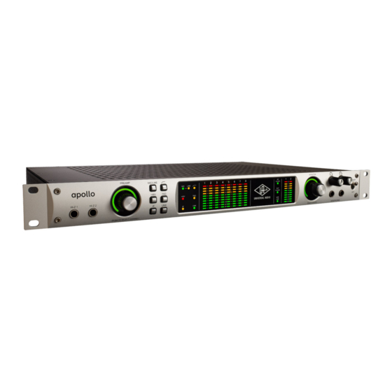
Page 10: Front Panel
Front Panel This section describes the features and functionality of all controls and visual elements on the Apollo front panel. Note that all front panel functions, except the headphone volume knobs and power switch, can be controlled remotely with the included Console software application. - Page 11 When enabled, the polarity (aka “phase“) of the input channel’s signal is inverted. Polarity affects the Mic, Line, and Hi-Z inputs. Polarity inversion can help reduce phase cancellations when more than one microphone is used to record a single source. Apollo FireWire Hardware Manual Front Panel...
- Page 12 1 – 4, by reducing the preamp gain or engaging the Pad (#7) and readjusting gain as needed. (continued) Apollo FireWire Hardware Manual Front Panel...
- Page 13 (15) External Clock When Apollo is set to use an external clock as the master clock source and a valid clock signal is detected at the specified port, the External Clock LED is solid green. Apollo can be configured to use an external clock from the Word Clock, S/PDIF, or ADAT inputs.
- Page 14 (21) Headphone Outputs 1 & 2 These ” stereo TRS phone jacks are for connecting stereo headphones to Apollo. Headphone outputs 1 & 2 are individually addressable by the device drivers and the Console application. Unique mixes can be created for each headphone output, or they can be switched to mirror the monitor outputs in the Console application.
-
Page 15: Rear Panel
48V phantom power is available via the front panel switch (when the channel is selected), or from within the Console application. Adjacent channel pairs can be linked for easy stereo adjustments. Stereo links for channels 1–2 and 3–4 can be established using the front panel Link button or the Console application. Apollo FireWire Hardware Manual Rear Panel... -
Page 16: Digital I/O
Use the Power switch on the front panel to power the unit on and off. Important: Do not disconnect the power supply while Apollo is in use, and confirm the Power switch is in the “off” position before connecting or disconnecting the power supply. - Page 17 Console application. When Apollo is set to use external word clock as its clock, Apollo is a word clock slave. If the incoming external word clock is within ±0.5% of a supported sample rate (44.1 kHz, 48 kHz, 88.2 kHz, 96 kHz, 176.4 kHz, 192 kHz), Word Clock Out will mirror Word Clock In with a slight phase delay (about 40ns).
-
Page 18: Host I/O
Apollo’s termination switch should only be engaged when Apollo is set to sync to external word clock and it is the last device at the receiving end of a word clock cable. For example, if Apollo is the last “slave” unit at the end of a clock chain (when Apollo’s word clock out port is not used), termination should be active. -
Page 19: Installation & Configuration
For complete details about how to operate Console, refer to the Apollo Software Manual. Multi-Unit Cascading When more I/O and/or DSP is needed, two Apollo FireWire interfaces can be cascaded together via FireWire in a multiple-unit configuration. Up to four Apollo models of any type can be cascaded together if all units are connected via Thunderbolt (Mac only). -
Page 20: Interconnections
Interconnections Installation Notes • Apollo may get hot during normal operation if it doesn’t receive adequate airflow circulation around its chassis vents. For optimum results when mounting Apollo in a rack, leaving at least one empty rack space above the unit to allow adequate airflow for cooling is recommended. -
Page 21: Typical Setup
Typical Setup This diagram illustrates an Apollo setup that might be used by two musicians that are recording simultaneously. In this setup, only analog devices are connected; digital I/O is not used. The example shows an electric guitar and electric bass connected to the Hi-Z inputs. Microphones are connected to XLR inputs of channel 3 and 4, and a stereo keyboard instrument is connected to line inputs 5 and 6. -
Page 22: Advanced Setup
• Mic/Line switch for channels 3 and 4 are set to “Mic” • Four additional mic preamps from UA’s 4-710d are routed into Apollo via ADAT Lightpipe • Apollo is the master clock device; the 4-710d clock source is set to external word clock and the 4-710d Termination switch is engaged... -
Page 23: Firewire Basics
Some FireWire devices can be “bus powered” which means the device derives its operating electricity from the FireWire bus itself without a power supply of its own. Apollo cannot be bus powered and it does not supply bus power from its FireWire ports to other devices. - Page 24 FireWire ports or a peripheral FireWire repeater, or any combination of the two in a “tree chain” topology. Apollo can function as a FireWire repeater, by using the unused port on the unit to connect other FireWire devices. Note that Apollo does not supply FireWire bus power to downstream devices.
- Page 25 FireWire 800 devices are backwards compatible and can be connected to a FireWire 400 bus using a 9-pin to 6- pin FireWire cable or adapter. However in this scenario any 800 megabit-capable devices on the bus (including Apollo) will operate at a maximum of 400 megabits because FireWire bandwidth cannot exceed the maximum bus speed of the host computer.
-
Page 26: Specifications
Default Input Impedance 5.4K Ohms (variable via Unison preamp plug-ins) Gain Range +10 dB to +65 dB Pad Attenuation 20 dB (switchable per mic input) Maximum Input Level (minimum gain, Pad engaged) +26 dBu (continued) Apollo FireWire Hardware Manual Specifications... - Page 27 Frequency Response 20 Hz – 20 kHz, ±0.1 dB Signal-to-Noise Ratio 118 dB (A–weighting) Total Harmonic Distortion + Noise –106 dBFS Stereo Level Balance ±0.05 dB Output Impedance 600 Ohms Maximum Output Level +20 dBu (continued) Apollo FireWire Hardware Manual Specifications...
- Page 28 Port 1 = Channels 1 – 2, Port 2 = Channels 3 – 4 Word Clock Connector Type Lock Range ±0.5% of any supported sample rate Word Clock Input Termination 75 Ohms, switchable Synchronization Sources Internal, Word Clock, S/PDIF, ADAT (continued) Apollo FireWire Hardware Manual Specifications...
- Page 29 Shipping Weight (with box & accessories) 18 pounds Weight (bare unit) 9.1 pounds Package Contents Apollo Audio Interface (DUO or QUAD) External Power Supply 6’ FireWire 800 cable IEC AC Power Cable Set of (4) Rack-Mount Screws Getting Started URL Card...
-
Page 30: Hardware Block Diagram
Hardware Block Diagram Apollo FireWire Hardware Manual Block Diagram... -
Page 31: Troubleshooting
1. Power off Apollo 2. Press and hold the PREAMP (#2), LOW CUT (#5), and POLARITY (#8) controls 3. Power on Apollo while continuing to hold all three controls 4. After all front panel LEDs flash rapidly (after several seconds), release the controls... -
Page 32: Notices
The unit has been dropped, or the enclosure damaged. 11. Servicing - The user should not attempt to service the unit beyond that described in the operating instructions. All other servicing should be referred to qualified service personnel. Apollo FireWire Hardware Manual Notices... -
Page 33: Warranty
You may also have other rights which vary by state or country. Maintenance Apollo does not contain a fuse or any other user-replaceable parts. The unit is internally calibrated at the factory. No internal user adjustments are available. -
Page 34: End User License Agreement
Universal Audio, Inc. shall not be liable for errors contained herein or direct, indirect, special, incidental, or consequential damages in connection with the furnishing, performance, or use of this material. -
Page 35: Index
Preamp LEDs, 12 Analog I/O, 15 Internal Clock. See Clock LEDs Preamp Settings, 11 Apollo, 4 Line Inputs, 15 Rear Panel, 15 Apollo Software Manual, 7 Line Outputs, 15 S/MUX, 16 Block Diagram, 30 Link, 12 S/PDIF Ports, 17 Channel Select, 11... - Page 36 Universal Audio, Inc. 4585 Scotts Valley Drive Scotts Valley, CA 95066 USA Customer Service & Technical Support: +1-877-MY-UAUDIO (+1-877-698-2834) International: +1-831-440-1176 www.uaudio.com...
Need help?
Do you have a question about the apollo and is the answer not in the manual?
Questions and answers