LONGER RAY5 Manual
- User manual (47 pages) ,
- Quick start manual (2 pages) ,
- Instructions (2 pages)
Advertisement
SAFETY PRECAUTIONS
 ATTENTION
- The RAY5 engraves and cuts materials by the means of a high-energy diode laser beam.
The hazards associated with a high-energy diode laser beam include the possibility of fires, generation of hazardous and/or irritating toxic fumes, but more importantly damage to eyes and skin. ![]()
Laser engravers are divided into several internationally valid classes based on their performance and the risk of injury. The RAY5 falls into the Class IV (Class 4 IEC standard focus on the American FDA classification).

| Laser class | Class Definition |
| Class I | Class I levels of laser radiation are not considered to be hazardous. |
| Class IIa | Class IIa levels of laser radiation are not considered to be hazardous if viewed for any period of time less than or equal to 1x10³ seconds but are considered to be a chronic viewing hazard for any period of time greater than 1x10³ seconds. |
| Class II | Class II levels of laser radiation are considered to be a chronic viewing hazard. |
| Class IIIa | Class IIIa levels of laser radiation are considered to be, depending upon the irradiance, either an acute intrabeam viewing hazard or chronic viewing hazard, and an acute viewing hazard if viewed directly with optical instruments. |
| Class IIIb | Class IIIb levels of laser radiation are considered to be an acute hazard to the skin and eyes from direct radiation. |
| Class IV | Class IV levels of laser radiation are considered to be an acute hazard to the skin and eyes from direct and scattered radiation.hazard to the skin and eyes from direct and scattered radiation.and eyes from both direct and scattered radiation. |
The high energy laser beam can cause severe eye damage, including blindness and serious skin burns.
Improper use of the controls and modification of the safety features may cause serious eye injury and burns.
Please wear Personal Protective Equipment (PPE, safety glasses are designed to filter specific ranges of laser wavelength. The RAY5 safety glasses provided are specific for LONGER Laser Module;) when using the engraver.
- DO NOT look directly into the laser beam;
- DO NOT aim the laser beam at reflective surfaces;
- DO NOT operate the laser without PPE protection for all persons nearby in the proximity of the RAY5;
- DO NOT allow unsupervised access to the RAY5 to children;
- DO NOT allow access near the RAY5 to pets;
- DO NOT modify or disable any safety features of the laser system;
- DO NOT touch the high energy laser beam;
- We strongly recommend placing the machine in a well-ventilated room, and at the same time, the door of the room has a sealing effect and the windows have curtains, so as to effectively avoid looking directly at the laser beam and some smoke and steam, Particles and other highly toxic substances. At the same time, you can pay attention to the Longer products (cover) in the follow-up.
- The high-energy diode laser beam can produce extremely high temperatures and significant amounts of heat as the substrate material is burned away while engraving and cutting. Some materials are prone to catch fire during cutting operations creating flame, fumes and smoke.
- Although the RAY5 has a built in flame sensor, this technology should NOT be considered 100% accurate and should be seen only as a warning system.
P.S. During the working process of RAY5, if a flame is found, the machine will stop the laser and make a sound to indicate abnormal conditions. Please pay attention to the working status of the machine. - During operation to ensure that any flare ups/ flame are properly contained and extinguished.
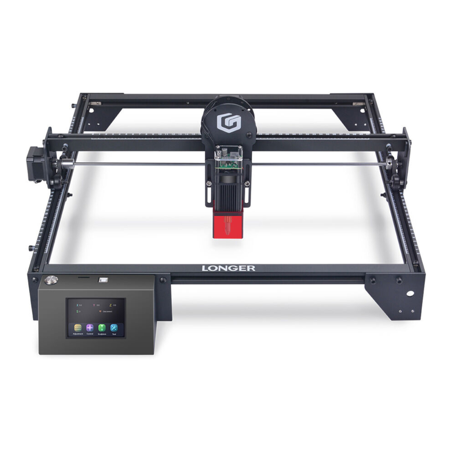
LASER ENGRAVER INTRODUCTION

- Y-Axis Motor
- X-Axis Beam
- Laser Module
- Touch Screen
- Synchronous Shaft
- Support Feet
- Left Frame
- Rear Frame
- X-Axis Motor
- Laser Holdel
- Power Switch
- TF Card Slot
- USB Port
- Control Box
- Front Frame
- Right Frame
- Power Port
PACKING LIST

INSTALLATION STEPS
STEP 1
- Place the profiles on a flat table in order.
- Place two corner grooves into the profiles referring to diagram. Pay attention to the direction of the corner groove.
- Tighten the M5*25 screw with M5 washer into frames.
- Tighten the M5 screws on the corner grooves.


STEP 2

STEP 3
Place two corner grooves into the front frame first and pay attention to the orientation Tighten the M5*25 screw with M5 washer into frames. Tighten the M5 screws on the corner grooves.

STEP 4
Preparation:
Support feet x3, engraving machine control box, M5*16 hexagon socket cup head screw x8, M5*8 hexagon socket round head screw x1, nylon isolation column (7*5*6) x1.

According to the figure, install the supporting foot, the control box of the engraving machine, and the left profile limit screw in the corresponding position.

STEP 5
Preparation:
Timing belt x2, M5 T-shaped nut x4, M5*6 hexagon socket head screw x4.

- Place a timing belt along the red arrow with the tooth face down.
- Put the T-shaped nut on one end of the belt, use an L-shaped screwdriver (M4) to rotate the T-shaped nut, then screw in the M5*6 screw to fix one end of belt.
- Tighten the belt by hand, then fix another end of belt in the manner of previous step.
- Fix another belt on left frame in the same way.


STEP 6
Preparation:
Laser module, Thumb Screwx2, M3*6 hexagon socket round head screw x2, nylon isolation column (5*3*3) x2.

Use Thumb Screw to fix the laser module to the X-axis frame laser head sheet metal, and the height of the laser head should not be too high.

The screw passes through the isolation cylinder, after installation, the laser head can move up and down is better.
STEP 7
Connect the cable to the motor and the laser head as shown in the figure.

Note: Fix the cable with a cable tie and sheet metal to ensure that the cable has enough length to ensure that the length of the cable is sufficient for the laser head to move to the limit position.
STEP 8
Focusing:
Place the wooden board under the engraving head, loosen the Thumb Screw, loosen the laser head adjustment plate, place the focusing column under the laser profile (refer to the figure below), and tighten the Thumb Screw.

Please reference more details on digital manual in TF card about the operation of Laser Engraver and installation of LaserGRBL or LightBurn.
Please join in our Facebook Group: LONGER Laser Engraver Official Group
Email: support@longer3d.cn
Documents / ResourcesDownload manual
Here you can download full pdf version of manual, it may contain additional safety instructions, warranty information, FCC rules, etc.
Advertisement


Need help?
Do you have a question about the RAY5 and is the answer not in the manual?
Questions and answers