
Related Manuals for Assa Abloy DMS-D


Summary of Contents for Assa Abloy DMS-D
- Page 1 User manual Components ASSA ABLOY DMS-D Experience a safer and more open world Original instructions...
- Page 2 Version: Publication date: 2024-12-13 Content subject to change without notice. ASSA ABLOY as word and logo are trademarks owned by the ASSA ABLOY Group. Copyright © ASSA ABLOY. ® The Bluetooth word mark and logos are registered trademarks owned by Bluetooth SIG, Inc. and any use of such marks by ASSA ABLOY is under license.
-
Page 3: Table Of Contents
Spare parts and liability ................................General information....................................Purpose and use of the instructions............................. Manufacturer ....................................Target groups....................................Description......................................... DMS-D Description ..................................Identification....................................Connection to control unit ..............................Technical Data......................................11 Key Functions......................................12 Important Notes ....................................... 13 Select the mode of operation ................................14 Carrying out functions .................................... -
Page 4: List Of Changes
List of changes User manual List of changes Change Location Complete revision of all sections and content Entire document New section structure Entire document Revision of all graphics Entire document 4/22 2024-12-13 102-903109272_en_2.0... -
Page 5: Safety
User manual 1 Safety Safety Presentation of warning signs DANGER Warning against an imminent or latent hazardous situation that can lead to electric shock and cause serious injury or death. DANGER Warning against an imminent hazardous situation that can lead to severe injury or death. WARNING Warning against a latent hazardous situation that can lead to severe injuries or death and cause sub- stantial property damage. -
Page 6: State Of Technology
1 Safety User manual State of technology NOTICE Installation, commissioning, inspection, and maintenance must only be done by approved technicians. We recommend you to have a service agreement. Record the work in the check list and give it to the customer for safe keeping. This system was developed using state of the art technology and officially recognized technical safety regu- lations. -
Page 7: General Information
The illustrations are for basic understanding and may differ from the actual presentation. Specific repres- entations are contained in the drawings. NOTICE A replacement of the instructions is available from the supplier or on the website. Manufacturer ASSA ABLOY Entrance Systems AB Box 131 SE-261 22 Landskrona Sweden Phone: +46 10 4747 000... -
Page 8: Description
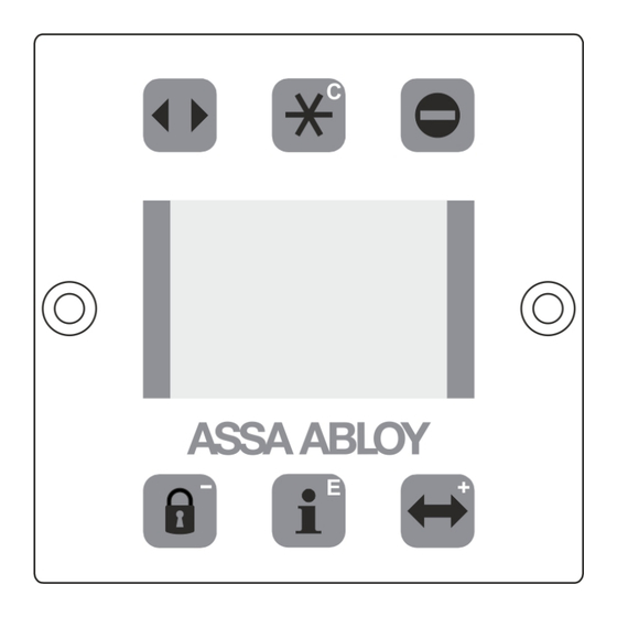
3 Description User manual Description DMS-D Description The DMS-D Digital Mode Selector with Display is a con- venient input and output unit for operating and program- ming control units in our door operators. Logically arranged buttons allow intuitive operation of the door and navigation through the operator-specific menu structure. -
Page 9: Connection To Control Unit
User manual 3 Description BUILT-IN TYPE Rear view Side view Front view 12 11 Connection to control unit Connection on CAN-bus: Plug in the connecting cable to the CAN-port (11) and connect it to the CAN-port on the STG (twisted-pair cable). - Page 10 3 Description User manual Connect to the control unit… DMS-D CANH CANH (white) CANL CANL (brown) µP +24V +24V (green) (yellow) S1-1 S1-2 STM 20... S1-1 S1-2 ON*=CAN-C ON*=DMS1 STG 19... OFF=CAN-O OFF=DMS2 STG 127... Control lock *Factory settings ON=CAN-C...
-
Page 11: Technical Data
User manual 4 Technical Data Technical Data Supply voltage: 24 VDC from CAN bus Connected load: < 2 W Dimension of front panel: 60 x 60 mm, adapted for Feller or Jung systems Dimension built-in type: 92 x 44 mm Temperature range: -20…... -
Page 12: Key Functions
5 Key Functions User manual Key Functions Function Automatic operation Hold-open operation One-way operation Locked STA: reduced opening width DFA: manual operation • Display for additional information • Access to parameter menu • Start procedure for service lock • Restart STG: press > 5 s •... -
Page 13: Important Notes
User manual 6 Important Notes Important Notes CAUTION Inappropriate modification of the settings could impair the correct and safe function of the installation! Access to parameters End customer or operator of the installation Key sequence: NOTICE Parameters or data that are not present in the control unit, or are only present as unknown values, will be indicated by a question mark and can be displayed in different ways depending on their type. -
Page 14: Select The Mode Of Operation
7 Select the mode of operation User manual Select the mode of operation Operating mode Displayed Symbol STA Sliding Door Automatic Automatic Continuously open Continuously open One-way One-way Manual Or press 2 s Manual Locked Locked Reduced opening width Automatic Operating mode Displayed Symbol DFA Swing Door... - Page 15 User manual 7 Select the mode of operation Operating mode Displayed Symbol DFA Swing Door One-way One-way Locked Locked Manual operation Manual 102-903109272_en_2.0 2024-12-13 15/22...
-
Page 16: Carrying Out Functions
8 Carrying out functions User manual Carrying out functions Restarting the Control Unit Press > 5 s Reset controller? Restart Hardware Press > 12 s Connect to the control unit… The control unit has been connected (example) DFA 127 V2.21 Basic operator NOTICE Only in Operation mode “Locked”. -
Page 17: Reading Out Information
System Information Press approx. 2 s Browsing through information screens Software SL600 VX.X DMS-D VX.X Service point Last error 37 Motor current Maintenance NOTICE Return to the standard screen by pressing the key or automatically after 20 s. -
Page 18: Fault Indications
10 Fault indications User manual Fault indications Fault indications Any current operational faults in the drive system, will be displayed in the standard screen. The display changes between normal / inverse after 2 s. AKI > active AKI > active If several faults are active, they will be numbered: e.g. -
Page 19: Lock Control Panel
User manual 11 Lock control panel Lock control panel NOTICE Undesirable manipulation on the control unit by unauthorized persons, can be hindered in a simple manner. Control lock via keypad Displayed on LCD Press the key sequence as shown. No settings can be made on the control unit. -
Page 20: Parameter Settings With Slider Controls
12 Parameter settings with slider controls User manual Parameter settings with slider controls NOTICE With the type "low energy", the parameters can only be changed by qualified personnel. The following example of the closing speed explains how to set the parameters of the door. Closing speed example Step Operation... -
Page 21: Taking Out Of Service And Disposal
User manual 13 Taking out of service and disposal Taking out of service and disposal 13.1 Decommissioning NOTICE After each temporary shutdown a new commissioning must be carried out. When the system is taken out of service: Disconnect the system from the mains supply. Unplug from any existing battery. - Page 22 Building on the long-term success of the Besam, Craw- ford, Albany and Megadoor brands, we offer our solutions under the ASSA ABLOY brand. Our products and services are dedicated to satisfying end-user needs for safe, secure, con- venient and sustainable operations.
Need help?
Do you have a question about the DMS-D and is the answer not in the manual?
Questions and answers