
Related Manuals for Assa Abloy effeff 970-TSBC-30-10


Summary of Contents for Assa Abloy effeff 970-TSBC-30-10
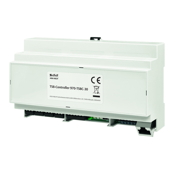
- Page 1 Escape route technology www.assaabloy.com/de TSB Controller 970-TSBC-30–10 User manual D0134300...
- Page 2 Firmware version 4.0.1220 FT Managerversion 4.0.1220 Open Source Licenses ASSA ABLOY Sicherheitstechnik GmbH has the source code of the software used in the scope of Open Source licenses (such as FreeRTOS™, newlib, lwIP) available on request: http://www.assaabloy.com/com/global/opensourcelicense/ Publisher...
-
Page 3: Table Of Contents
Table of contents Notes ..........4 About this manual . -
Page 4: Notes
Notes About this manual This manual was written for electricians and appropriately trained personnel. The manual was designed to enable you to install and operate the device safely and make full use of the permitted range of applications the control terminal has to offer. Meaning of the symbols Danger! Safety notice: Failure to observe these warnings will lead to death or serious... -
Page 5: Safety Instructions
Danger due to faulty commissioning: In order to ensure the safety of the prod- uct, commissioning must be performed by a qualified person. ASSA ABLOY Sicher- heitstechnik GmbH offers training for qualification in the requisite skills. -
Page 6: Intended Use
Intended use The TSB Controller 970-TSBC-30–10 (TSB Controller) serves as a link between a PC and the TS bus. Data transfer between the PC and TSB Controller takes place via Ethernet. Data transmission between the TSB Controller and the individual escape door control units or control terminals (peripherals) takes place via the TS bus. -
Page 7: Operation
Operation General description Bus technology is primarily used in modern control technology in equipment TS bus (door where a larger number of individual devices are monitored and controlled. control bus) The TS bus uses two-wire technology to ensure that installation between the individual devices and a central control point is restricted to a two-wire bus line. -
Page 8: Control And Monitoring
Note! Functionality in the event of PC failure: If the PC should crash, the TS bus will continue to function. The doors can be controlled using an optional control panel instead. If the TS bus fails, the safety functions in escape door control units or escape door control terminals and connected components, such as escape door strikes and emergency open switches, remain operative for safety reasons. -
Page 9: Installation
Installation Warning! Danger due to faulty Installation: The bus controller module and connected devices may only be installed and set up for operation by a qualified electrician. Danger due to non-compliance with the applicable regulations: You must ob- serve and comply with the German Electrical Engineering Association (VDE) and local electricity company regulations when installing equipment. -
Page 10: Lines And Wiring
Lines and wiring You must comply with a few installation requirements to ensure that the system Connect TS bus functions correctly. Please follow the instructions below and carry out installation and connection work carefully. TS bus installation Important! Disturbances due to excessive total line length and line resistances: The total length of the bus line should be no longer than 1,000 m and resistance in the line to peripherals should be no greater than 65 ohm. -
Page 11: Bus Controller Installation
Bus controller installation The TSB Controller is intended for installation in a suitable electrical distributor. It is mounted on top-hat rails according to DIN EN 60715 TH35. The wiring takes place via screw-type terminals. The installation location of the TSB Controller distributor must meet the following Installation conditions: location... -
Page 12: Connections
Connections Fig. 2 : Terminal strip Functional earthing – + 24 23 22 21 20 19 18 17 16 15 14 13 12 11 10 9 8 7 4 3 2 1 nc c no nc c no nc c no nc c no 11 12 Jumper inserted... - Page 13 Pos. No. Description Pos. No. Description Tab. 1: Key for Fig. 2 reserved TSB ground reserved TSB data supply + 24V supply 0V Input 1 Relay 1 no Input 2 Relay 1 c Ground Relay 1 nc Input 3 Fire alarm system + Fire alarm system - Relay 2 no Relay 3 no...
-
Page 14: Resetting To Factory Settings
Resetting to factory settings Resetting to factory settings will lose all changes to the operating data. Reset to factor y settings The factory settings are reset from the basic state or from a fault. Set DIP switch 2 to OFF if necessary (Fig. 2– ... -
Page 15: Led Signalling
LED signalling The LEDs are used for status indication. Start, basic state (normal operation), data traffic, faults and the reset to factory settings are indicated and documented by the behaviour of the LEDs. LED red LED yellow LED green Tab. 2: LED signals After switching on/ booting Booting procedure after switching on... -
Page 16: Set-Up Operation
Set-up operation Check list Check installation Inspecting · Is the power supply to the peripherals secured? · Are all peripherals, escape door strikes and contacts connected? · Is the bus line connected to the peripherals? · Is the power supply connected to the controller? ·... -
Page 17: Network Connection
Network connection You need to establish a network connection between the TSB Controller and your PC, so that you can access the web interface in the FT Manager . This can be done in several ways: · Direct network connection using a cross-over cable (included in supply package) ·... -
Page 18: Ft Manager
FT Manager Connection to service PC FT Manager The network connection between the TSB Controller and a service PC is estab- lished using a cross-over cable. The escape route technology is configured under Windows ® 10 using FT Manager and a web browser. System settings The system settings on the controller, such as TCP/IP address assignment, are System... - Page 19 Fig. 4 : Configuring the network connection Set-up operation...
-
Page 20: Connection To Server Pc
Opening the FT Manager Once configuration is complete, you can then open up the FT Manager in a web Web browser browser. Start your web browser. Enter the following URL in the address bar: https://1.1.1.1 and confirm the entry. A security notice will appear. Note! Unknown security certificate warning message: The security certification encrypts communication between the computer and the 970-TSBC. - Page 21 Fig. 5 Note on the safety certificate Fig. 6 Start interface of the FT Manager Set-up operation...
-
Page 22: Technical Data
Length of line max. 1000 m Housing Distributor installation top-hat rail in accordance with DIN EN 60715 TH35 Certification ASSA ABLOY Sicherheitstechnik GmbH Bildstockstraße 20 72458 Albstadt GERMANY The EU declaration of conformity is available in the download area of www.assaabloy.com/de... -
Page 23: Warranty, Disposal
Warranty, disposal Latest news The latest information is available at: www.assaabloy.com/de Warranty The statutory warranty periods and ASSA ABLOY Sicherheitstechnik GmbH’s Terms and Conditions of Sale and Delivery (www.assaabloy.com/de) apply. Warranty, disposal... -
Page 24: Disposal
Disposal The following applies to products marked with the symbol (crossed out dustbin): The applicable environmental protection regulations must be observed. Do not dispose of lamps, disposable and rechargeable batteries, electrical devices or personal data in the household waste. Lamps and used disposable and rechargeable batteries must be removed from the device without damaging them and then disposed of separately. - Page 25 Remove batter y before disposal Important! Material damage may result from removing the battery:It is not necessary to remove the battery during normal use of the device. Opening the housing can damage the device. · Only open the housing before disposing of the battery Disconnect all clamps.
- Page 26 Product WEEE reg. no. DE 69404980 You must dispose of the product correctly as electronic scrap after use and take it to a local collection point for recycling free of charge. You have the following additional options for free disposal through the distribu- ·...
- Page 28 The ASSA ABLOY Group is the global leader in access solutions. Every day we help people feel safe, secure and experience a more open world. ASSA ABLOY Sicherheitstechnik GmbH Bildstockstrasse 20 72458 Albstadt GERMANY Tel. + 49 7431 123-0 albstadt @ assaabloy.com...
Need help?
Do you have a question about the effeff 970-TSBC-30-10 and is the answer not in the manual?
Questions and answers