Table of Contents
Advertisement
Quick Links
User Guide
User Manual
MODEL 5650
Use and Disclosure of Data
Information contained herein is classified as EAR99 under the
U.S. Export Administration Regulations.
Export, reexport or diversion contrary to U.S. law is prohibited.
WATER IN OIL MONITOR/WATERCUT ANALYZER
USE AND DISCLOSURE OF DATA
Information contained herein is classified as EAR99 under the U.S. Export Administration Regulations. Export, reexport or diver-
sion contrary to U. S. law is prohibited.
M5650, Rev. C/ May 2022
Advertisement
Table of Contents

Related Manuals for Teledyne 5650


Summary of Contents for Teledyne 5650
- Page 1 User Guide User Manual MODEL 5650 Use and Disclosure of Data Information contained herein is classified as EAR99 under the U.S. Export Administration Regulations. Export, reexport or diversion contrary to U.S. law is prohibited. WATER IN OIL MONITOR/WATERCUT ANALYZER USE AND DISCLOSURE OF DATA Information contained herein is classified as EAR99 under the U.S.
-
Page 5: Special Conditions For Safe Use
Model 5650 Zone 1 (Type of Protection: Ex db) ___________________________________________________________________________ Special Conditions for Safe Use • Read and follow the installation instructions • Maximum process temperature is 130 • Due to the risk of static charges, clean surface of the equipment using a damp cloth. -
Page 7: Warranty
LEGAL STATEMENT Teledyne Analytical Instruments, the Teledyne Analytical Instruments logo, the Teledyne rhomboid, and Model 5650 are registered and/or unregistered marks of Teledyne Analytical Instruments, also referred to as “the Company.” All rights reserved. No part of this documentation may be reproduced in any form or by any means or used to make any derivative work (such as translation, transformation, or adaptation) without written per- mission from the Company. -
Page 8: Important Notice
MODEL 5650 WATER IN OIL MONITOR/WATERCUT ANALYZER Microsoft, Windows, Windows 2000, Windows Me, Windows XP, Windows NT, Windows Vista, Win- dows 7, Internet Explorer and MS-DOS are either trademarks or registered trademarks of Microsoft Cor- poration in the United States and other countries. Solaris and JAVA are either trademarks or registered trademarks of Sun Microsystems, Inc. - Page 9 MODEL 5650 WATER IN OIL MONITOR/WATERCUT ANALYZER This page is intentionally left blank. USE AND DISCLOSURE OF DATA Information contained herein is classified as EAR99 under the U.S. Export Administration Regulations. Export, reexport or diversion contrary to U. S. law is prohibited.
-
Page 10: Table Of Contents
1.3. General Safety Information ...................... 1-2 2. Introduction............................2-1 2.1. Operating Principle........................2-1 2.2. Process Temperature Considerations..................2-2 2.3. Model 5650 Monitor/Analyzer Series .................. 2-3 2.3.1. S-Series ..........................2-3 2.3.2. F-Series...........................2-3 2.3.3. I-Series............................2-4 2.4. Additional Variations ......................... 2-4 2.4.1. Static Mixer ..........................2-4... - Page 11 MODEL 56500 WATER IN OIL MONITOR/WATERCUT ANALYZER 6.1.2. HART Communication - Basics .....................6-1 6.1.3. HART Setup ..........................6-2 6.2. Universal Commands ........................ 6-2 6.3. Device Specific Commands ...................... 6-3 Area Certificate..........................A-1 HART Connection ..........................B-1 B.1. Calibration...........................B-1 B.1.1. Standardization ........................B-1 B.1.2.
-
Page 12: About This Manual
WATER IN OIL MONITOR/WATERCUT ANALYZER 1. About This Manual This manual provides instructions on the features and usage of the Model 5650 Water in Oil Monitor/ Water Cut Analyzer (also referred to as “Monitor/Analyzer”). It also provides information on configuration, operation, maintenance, specifications, and trouble shooting. This user manual assumes the reader has a basic knowledge of liquid analytical instrumentation. -
Page 13: General Safety Information
MODEL 5650 WATER IN OIL MONITOR/WATERCUT ANALYZER 1.3. General Safety Information WARNING: FLAMMABLE LIQUID USAGE! THE MONITOR/ANALYZER IS HOUSED IN AN FLAME PROOF/EXPLOSION PROOF HOUSING AND IS DESIGNED FOR USE IN A CLASS 1, DIVISION 1, GROUP A, B, C, D ENVIRONMENT. IT IS THE CUSTOMER'S RESPONSIBILITY TO ENSURE SAFETY ESPECIALLY WHEN FLAMMABLE LIQUIDS ARE BEING ANALYZED SINCE THE POTENTIAL OF LEAKS ALWAYS EXIST. - Page 14 MODEL 5650 WATER IN OIL MONITOR/WATERCUT ANALYZER Observed all pertinent regional and local safety regulations when handling and disposing of hazardous material, batteries, and other similar items that may fall under the classification of hazardous material. The Monitor/Analyzer is designed for measuring water content in hydrocarbon liquids. This instrument produces a 4-20 mA signal that is proportional to the measured water content over the analysis range.
- Page 15 MODEL 5650 WATER IN OIL MONITOR/WATERCUT ANALYZER This page is intentionally left blank. USE AND DISCLOSURE OF DATA Information contained herein is classified as EAR99 under the U.S. Export Administration Regulations. Export, reexport or diversion contrary to U. S. law is prohibited.
-
Page 16: Introduction
MODEL 5650 WATER IN OIL MONITOR/WATERCUT ANALYZER 2. Introduction The Model 5650 Water-In-Oil Monitor/Watercut Analyzer is a sophisticated instrument designed to measure water concentration in oil. It consists of an electronics assembly and a Capacitance Probe section. The Monitor/Analyzer is housed in an explosion proof housing. Certain versions may be fitted with a window and a control unit display. -
Page 17: Process Temperature Considerations
MODEL 5650 WATER IN OIL MONITOR/WATERCUT ANALYZER 2.2. Process Temperature Considerations CAUTION: The Monitor/Analyzer is certified for up to 130° C surface temperature (T4) for EXD components and an ambient temperature up to 60° C. This must not be exceeded. -
Page 18: Model 5650 Monitor/Analyzer Series
MODEL 5650 WATER IN OIL MONITOR/WATERCUT ANALYZER 2.3. Model 5650 Monitor/Analyzer Series The Monitor/Analyzer is available in 3 main variations: 2.3.1. S-Series The S-Series sensor is a spool section for inline measurements from 1 to 8 inch. Sizes 1 to 3 inch are available with threaded connections. -
Page 19: I-Series
MODEL 5650 WATER IN OIL MONITOR/WATERCUT ANALYZER 2.3.3. I-Series The I-Series sensor is an insertion model that can be provided as a fixed length flanged unit or supplied with a kit providing retraction under pressure. Materials for wetted parts is available as SS316L or higher qualities such as Duplex, Super Duplex or other specialized steels. -
Page 20: S-Series - Flanged And Threaded Version
MODEL 5650 WATER IN OIL MONITOR/WATERCUT ANALYZER 2.4.2. S-Series - Flanged and Threaded Version The S-Series sensor consists of a EXD certified Electronics Enclosure with cable entries for electrical wiring, a spool section for mounting into the pipe line to be measured. Smaller sizes are well suited for installation into by-pass or fast-loop arrangements. -
Page 21: F-Series - Fully Flanged Analyzers
MODEL 5650 WATER IN OIL MONITOR/WATERCUT ANALYZER 2.4.4. F-Series - Fully Flanged Analyzers The F-Series sensor consists of a EXD certified Electronics Enclosure with cable entries for electrical wiring, a spool section for mounting into the pipe line to be measured. The EXD enclosure is available in different versions to suit different markets/ certification requirements. -
Page 22: I-Series - Flanged Version
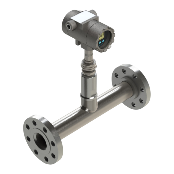
MODEL 5650 WATER IN OIL MONITOR/WATERCUT ANALYZER 2.4.6. I-Series — Flanged Version he flanged I-Series consists of a EXD certified Electronics Enclosure with cable entries for electrical wiring, a flanged probe section for insertion into the pipe line to be measured. The EXD enclosure is available in different versions to suit different markets/ certification requirements. - Page 23 MODEL 5650 WATER IN OIL MONITOR/WATERCUT ANALYZER 2.4.7.2 Installation into Smaller Pipe through a Pipe Bend or T-Section Installation into smaller pipe through a pipe bend, T-section or similar arrangement allowing probe to insert along the main line. Generally for 2” to 4”, but can be used also for larger pipe.
- Page 24 MODEL 5650 WATER IN OIL MONITOR/WATERCUT ANALYZER 2.4.7.4 I-Series — Version for Extraction under Line Pressure The non-flanged I-Series consists of a EXD certified Electronics Enclosure with cable entries for electrical wiring and a rod style probe section for insertion into the pipe line to be measured through a process gland.
- Page 25 MODEL 5650 WATER IN OIL MONITOR/WATERCUT ANALYZER Figure 2-16: Installation into Larger Pipe through a 2” or 3” Side Port USE AND DISCLOSURE OF DATA Information contained herein is classified as EAR99 under the U.S. Export Administration Regulations. Export, reexport or diversion contrary to U. S.
-
Page 26: Installation
MODEL 5650 WATER IN OIL MONITOR/WATERCUT ANALYZER 3. Installation CAUTION: Ensure that product marking is suitable for the classified area of installation. Ambient temperature shall not exceed 60 deg C. CAUTION: The housing must be protected against mechanical shocks. No drilling or machining must be done. -
Page 27: Electrical: 4-20Ma
MODEL 5650 WATER IN OIL MONITOR/WATERCUT ANALYZER 3.1. Electrical: 4-20mA 3.1.1. Power Supply - 4-20mA Current Loop Voltage: 12 to 26VDC (Floating/Isolated) Power Consumption: 0.66W The Monitor/Analyzer provides a 4-20mA analog signal that is proportional to the measured water content. The current loop must be powered externally and will provide sufficient power for the Monitor/Analyzer to operate. -
Page 28: Communication Rs-232 Interface
MODEL 5650 WATER IN OIL MONITOR/WATERCUT ANALYZER Figure 3-1: Monitor/Analyzer Wiring Terminal (2-Loop Powered) 3.1.3.1 Enclosure Cable Entries, Cable Glands, and Stopping Plugs For threaded entries use only already certified connection facil-ities suitable for application and rated for a minimum of 80°C. -
Page 29: Terminal Software
MODEL 5650 WATER IN OIL MONITOR/WATERCUT ANALYZER supplied RS-232 cable has a small PCB in the black RS-232 Connector and communication will not work with any other cable. Bits per second: 9600 Data Bits: Parity: None Stop Bits: Flow Control: None 3.3. -
Page 30: General Installation Guidelines
MODEL 5650 WATER IN OIL MONITOR/WATERCUT ANALYZER 3.4. General Installation Guidelines The following images provides a few pointers to good vs. bad installation. Key to a good measurement is to avoid slugging, partially filled pipes, gas/air pockets, fast pressure drops, open end outlets, pump interference and stratified water/oil. - Page 31 MODEL 5650 WATER IN OIL MONITOR/WATERCUT ANALYZER 5650 5650 5650 5650 Figure 3-6: Installation Location 5650 5650 Figure 3-7: Installation Location - At Outlet 5650 5650 Figure 3-8: Installation Location - Near Pipe Reducer/Expander USE AND DISCLOSURE OF DATA Information contained herein is classified as EAR99 under the U.S. Export Administration Regulations. Export, reexport or diversion contrary to U. S.
- Page 32 MODEL 5650 WATER IN OIL MONITOR/WATERCUT ANALYZER 5650 Figure 3-9: Installation Location - Do Not Install Near Pump 5650 Figure 3-10: Installation Location - DO Not Install on Suction Side of Pump Figure 3-11: Installation Location - Insert I-Series Against Flow USE AND DISCLOSURE OF DATA Information contained herein is classified as EAR99 under the U.S.
- Page 33 MODEL 5650 WATER IN OIL MONITOR/WATERCUT ANALYZER This page is intentionally left blank. USE AND DISCLOSURE OF DATA Information contained herein is classified as EAR99 under the U.S. Export Administration Regulations. Export, reexport or diversion contrary to U. S. law is prohibited.
-
Page 34: Field Calibration
MODEL 5650 WATER IN OIL MONITOR/WATERCUT ANALYZER 4. Field Calibration 4.1. Zero Offset 4.1.1. Field Calibration Overview Field calibration is the process of teaching the Monitor/Analyzer what level of capacitance corresponds to a given level of water content. This is a single point offset; the electronics will take care of the rest. -
Page 35: Temp Compensation
4.1.2.2.1.2. Calibration Samples Take sample as close in time as possible to the time of issuing the save command. Take sample from a location close to the MODEL 5650 Monitor. Ensure your sample is representative. Allow sample line/points to flush stagnant liquid to ensure a fresh sample for calibration. - Page 36 MODEL 5650 WATER IN OIL MONITOR/WATERCUT ANALYZER 4.2.1.1. Find the TC Record T1 and C1 as temperature and capacitance while running at a lower temperature. Record T2 and C2 as temperature and capacitance while running at an elevated temperature. Calculate TC using the formula below.
- Page 37 MODEL 5650 WATER IN OIL MONITOR/WATERCUT ANALYZER This page is intentionally left blank. USE AND DISCLOSURE OF DATA Information contained herein is classified as EAR99 under the U.S. Export Administration Regulations. Export, reexport or diversion contrary to U. S. law is prohibited.
- Page 38 Default is high. Temperature Coefficient Factor. Allows values between 0.5 and 2, maximum 4 tec 1.0007 [enter] decimals This command will tell MODEL 5650 to Save [enter] save its latest capacitance and temperature measurement as a calibration reference save value to be used with the cal command.
- Page 39 MODEL 5650 WATER IN OIL MONITOR/WATERCUT ANALYZER Command Action Terminal Output Example Sets the percentage value used after cal to match the pF value stored using store. The internal calibration table will be offset using the value saved with command save.
-
Page 40: Hart
(4th) variable protocol unit data 6.1.1. Introduction Model 5650 complies with HART protocol revision 6. This document specifies all device specific features and documents HART protocol implementation. 6.1.2. HART Communication - Basics HART (Highway Addressable Remote Transducer) is a digital protocol for field communication. It is widely accepted as a standard for digitally enhanced 4-20 mA communication with smart and microprocessorbased field devices. -
Page 41: Hart Setup
The following universal commands are implemented. Please refer to your HART documentation for extensive information on each of these commands. Commands from 0-100 in the HART protocol are standardized, i.e. all common HART filed communicators can interact with the 5650 using these commands without any setup or programming being required. Command No. -
Page 42: Device Specific Commands
MODEL 5650 WATER IN OIL MONITOR/WATERCUT ANALYZER Command No. Command Description Command 43: Set primary variable 0. Command 45: Trim loop current zero. Command 46: Trim loop current gain. Command 48: Read additional device status. Command 56: Write device variable transducer serial number. - Page 43 MODEL 5650 WATER IN OIL MONITOR/WATERCUT ANALYZER Byte Description Action Result Request Data Bytes: none Store current value 0-3, float (capacitance) of capacitance and Command Response Data Bytes: temp. Return values 4-7, float (temperature) to master Response Codes: 0x0 Success...
- Page 44 MODEL 5650 WATER IN OIL MONITOR/WATERCUT ANALYZER Byte Description Action Result 0-50, 3 byte X 17 entries Request Data Bytes: 0-1 : unsigned int = Capacitance 2: unsigned char = Water Content (%) Write a complete Command cap/H O table to...
- Page 45 MODEL 5650 WATER IN OIL MONITOR/WATERCUT ANALYZER This page is intentionally left blank. USE AND DISCLOSURE OF DATA Information contained herein is classified as EAR99 under the U.S. Export Administration Regulations. Export, reexport or diversion contrary to U. S. law is prohibited.
-
Page 46: Area Certificate
MODEL 5650 WATER IN OIL MONITOR/WATERCUT ANALYZER Appendix A. Area Certificate Figure A-1: Area Certificate USE AND DISCLOSURE OF DATA Information contained herein is classified as EAR99 under the U.S. Export Administration Regulations. Export, reexport or diversion contrary to U. S. - Page 47 MODEL 5650 WATER IN OIL MONITOR/WATERCUT ANALYZER This page is intentionally left blank. USE AND DISCLOSURE OF DATA Information contained herein is classified as EAR99 under the U.S. Export Administration Regulations. Export, reexport or diversion contrary to U. S. law is prohibited.
-
Page 48: Hart Connection
MODEL 5650 WATER IN OIL MONITOR/WATERCUT ANALYZER Appendix B. HART Connection HART is connected the same way as 4-20mA (see Output section for detailed write up of how 4- 20mA is connected). A 280 Ohm resistor is put across the 4-20mA interface. HART is a superimposed signal over 4-20mA fluctuating the voltage. -
Page 49: Electrical Calibration
0% Water for Low range unit is 178 ±1% pF b. 0% water for High range unit is 25 ±1% pF 4. all Mdl. 5650 is calibrated through precision capacitor B.1.2.1. Electrical Calibration Procedure 1. Insert capacitor in pin 3 and 6 at sensor connection. - Page 50 MODEL 5650 WATER IN OIL MONITOR/WATERCUT ANALYZER Figure B-1: Attach Multimeter 3. Run Show command to show present reading. 4. Check 4-20mA output and see if output respond correctly to capacitor load (see note section for the correct starting point) 5.
- Page 51 MODEL 5650 WATER IN OIL MONITOR/WATERCUT ANALYZER This page is intentionally left blank. USE AND DISCLOSURE OF DATA Information contained herein is classified as EAR99 under the U.S. Export Administration Regulations. Export, reexport or diversion contrary to U. S. law is prohibited.
- Page 52 MODEL 5650 WATER IN OIL MONITOR/WATERCUT ANALYZER Appendix Capacitance Simulation & Verification Chart Low Range: 0-25% Water Cut High Range: 0-100% Water Cut Capacitance Value Capacitance Value 0-25% Range 0-100% Range (pF) (pF) 179.8 25.0 185.3 28.1 190.9 31.6 196.7 35.6...
- Page 53 MODEL 5650 WATER IN OIL MONITOR/WATERCUT ANALYZER This page is intentionally left blank. USE AND DISCLOSURE OF DATA Information contained herein is classified as EAR99 under the U.S. Export Administration Regulations. Export, reexport or diversion contrary to U. S. law is prohibited.
-
Page 54: Start Up & Routine Maintenance Procedure
7. Then follow the TAI testing procedure and install probe back to process and tighten all the bolts. 8. Then first open the outlet valve and then followed by inlet of the process isolation valve. 9. Now 5650 BS&W Analyzer is ready to read the actual process value. USE AND DISCLOSURE OF DATA Information contained herein is classified as EAR99 under the U.S. - Page 55 MODEL 5650 WATER IN OIL MONITOR/WATERCUT ANALYZER This page is intentionally left blank. USE AND DISCLOSURE OF DATA Information contained herein is classified as EAR99 under the U.S. Export Administration Regulations. Export, reexport or diversion contrary to U. S. law is prohibited.
-
Page 56: Introduction
MODEL 5650 WATER IN OIL MONITOR/WATERCUT ANALYZER Appendix E. 8080MK Field Mounted, Loop- Powered Indicator E.1. Introduction IME Model 8080MK Loop Powered Digital Indicators allow the process variable from any 4~20 mA current source to be monitored. Since the unit derives its power from the loop, no additional power supply or wiring is needed. -
Page 57: Functional Specifications
MODEL 5650 WATER IN OIL MONITOR/WATERCUT ANALYZER E.6. Functional Specifications Indication of Accuracy: 0.1% of calibrated range ±1 digit Calibration: Via membrane switches on the front panel Display Height: 8mm (0.3") high Stability Over Time: 0.1% of calibrated range ±1 digit over 6 months Over Range Indication: Indication of "Err"... -
Page 58: Ordering Information For 8080Mk
MODEL 5650 WATER IN OIL MONITOR/WATERCUT ANALYZER E.7. Ordering Information for 8080MK Model Description 8080MK Field Mounted LED Loop Powered Indicator Code Options, Housing Die cast Aluminum, Epoxy Coated SS316, Electro Polished Code Instrument Connection (T1) Conduit Size (T2) M16 x 2P (See note 1) ¾"... -
Page 59: Installation
MODEL 5650 WATER IN OIL MONITOR/WATERCUT ANALYZER Note: 1. Ports with M16 x 2P thread are not through holes, they are for use with Model 175RC and 175PM Mounting Brackets only. Figure E-1: Dimensions E.8. Installation E.8.1. Mounting Methods E.8.1.1. Model 175RC... - Page 60 MODEL 5650 WATER IN OIL MONITOR/WATERCUT ANALYZER Figure E-3: Model 175RC - Panel Mounting E.8.1.2. Model 175PM Figure E-4: Model 175PM - Pipe Mounting USE AND DISCLOSURE OF DATA Information contained herein is classified as EAR99 under the U.S. Export Administration Regulations. Export, reexport or diversion contrary to U. S.
- Page 61 MODEL 5650 WATER IN OIL MONITOR/WATERCUT ANALYZER Figure E-5: Model 175POM - Panel Mounting E.8.1.3. Model 175NR Figure E-6: Model 175NR - Vertical Pipe Mounting USE AND DISCLOSURE OF DATA Information contained herein is classified as EAR99 under the U.S. Export Administration Regulations. Export, reexport or diversion contrary to U. S.
- Page 62 MODEL 5650 WATER IN OIL MONITOR/WATERCUT ANALYZER Figure E-7: Model 175NR - Horizontal Pipe Mounting E.8.1.4. Model 175MM Figure E-8: Model 175MM - Wall/Panel Mounting USE AND DISCLOSURE OF DATA Information contained herein is classified as EAR99 under the U.S. Export Administration Regulations. Export, reexport or diversion contrary to U. S.
-
Page 63: Mounting Brackets
MODEL 5650 WATER IN OIL MONITOR/WATERCUT ANALYZER E.8.2. Mounting Brackets E.8.2.1. Model 5RC This simple hollow square mounting bracket constructed out of SS316 Stainless Steel, can be used to mount a variety of field devices, either on a wall or panel or a 2" Pipe. - Page 64 MODEL 5650 WATER IN OIL MONITOR/WATERCUT ANALYZER E.8.2.3. Model 175NR The Model 175NR is Stainless Steel Mounting Brackets made exclusively for the Model 8080 Instrument Enclosure to mount on a 2 " Pipe. This Bracket is available for customers who require all 3 ports on the enclosure for other purposes.
- Page 65 MODEL 5650 WATER IN OIL MONITOR/WATERCUT ANALYZER This page is intentionally left blank. USE AND DISCLOSURE OF DATA Information contained herein is classified as EAR99 under the U.S. Export Administration Regulations. Export, reexport or diversion contrary to U. S. law is prohibited.
-
Page 66: Technical Support
MODEL 5650 WATER IN OIL MONITOR/WATERCUT ANALYZER Appendix F. Technical Support This product is designed to provide you with reliable, trouble-free service. Contact your regional Technical Support if you have technical questions, need support, or if you need to return a product. - Page 67 City of Industry, CA 91748, USA Tel: 626-934-1500 www.teledyne-ai.com Copyright © 2020 Teledyne Analytical. Instruments. All rights reserved. P/N M5650, Rev. B / December 2020 USE AND DISCLOSURE OF DATA Information contained herein is classified as EAR99 under the U.S. Export Administration Regulations. Export, reexport or diversion contrary to U.S.
Need help?
Do you have a question about the 5650 and is the answer not in the manual?
Questions and answers