
Subscribe to Our Youtube Channel
Related Manuals for Metrohm 6.02101.010


Summary of Contents for Metrohm 6.02101.010
- Page 1 Measuring Module Analog 6.02101.010 Product information 8.0108.8004EN / 2022-01-12...
-
Page 3: Product Information
Metrohm AG Ionenstrasse CH-9100 Herisau Switzerland +41 71 353 85 85 info@metrohm.com www.metrohm.com Measuring Module Analog 6.02101.010 Product information 8.0108.8004EN / 2022-01-12... - Page 4 Disclaimer Deficiencies arising from circumstances that are not the responsibility of Metrohm, such as improper storage or improper use, etc., are expressly excluded from the warranty. Unauthorized modifications to the product (e.g. conversions or attachments) exclude any liability on the part of the manufacturer for resulting damage and its consequences.
-
Page 5: Table Of Contents
■■■■■■■■■■■■■■■■■■■■■■ Table of contents Table of contents 1 Overview Measuring Module Analog – Product description ..... 1 Measuring Module Analog – Product versions ....1 Measuring Module Analog – Overview ......2 Symbols and conventions ............ 2 Further information .............. 3 Accessories ................ -
Page 7: Measuring Module Analog - Product Description
The article number and serial number for identifying the product can be found on the type plate: (01) = Article number in accordance (21) = Serial number with GS1 standard (240) = Metrohm article number Certification Certification Technical specifications ■■■■■■■■... -
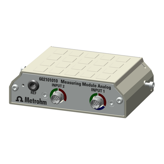
Page 8: Measuring Module Analog - Overview
Measuring Module Analog – Overview ■■■■■■■■■■■■■■■■■■■■■■ Measuring Module Analog – Overview Figure 1 Measuring Module Analog – Overview INPUT 1 INPUT 2 Connection socket for potentiometric sen- Connection socket for potentiometric sen- sors (green coding), temperature sensors sors (green coding) and temperature sensors (red coding) and polarizable sensors (blue (red coding) coding) -
Page 9: Further Information
Accessories Up-to-date information on the scope of delivery and on optional accesso- ries can be found on the Metrohm website. Download this information as follows: Downloading the accessories list 1 Go to https://www.metrohm.com. -
Page 10: Intended Use
■■■■■■■■■■■■■■■■■■■■■■ 2 Safety Intended use Metrohm products are used for the analysis and handling of chemicals. Usage therefore requires the user to have basic knowledge and experience in handling chemicals. Knowledge regarding the application of fire preven- tion measures prescribed for laboratories is also mandatory. -
Page 11: Requirements For Operating Personnel
Always have maintenance work and repairs on electrical components ■ carried out by a regional Metrohm service representative. Disconnect the product from the energy supply immediately if at least ■ one of the following cases occurs: –... -
Page 12: Design Of Warning Messages
Design of warning messages ■■■■■■■■■■■■■■■■■■■■■■ Design of warning messages There are 4 hazard levels for warning messages. The following signal words are used for classifying the hazard levels in warning messages: DANGER indicates a hazardous situation which, if not avoided, will ■... -
Page 13: Meaning Of Warning Signs
■■■■■■■■■■■■■■■■■■■■■■ Safety Meaning of warning signs This documentation uses the following warning signs: Table 2 Warning sign according to ISO 7010 Warning sign Meaning General warning sign Warning of electrical voltage Warning of hand injuries Warning of sharp object Warning of hot surface Warning of biological hazard Warning of toxic materials Warning of flammable materials... -
Page 14: Technical Specifications
Ambient conditions ■■■■■■■■■■■■■■■■■■■■■■ 3 Technical specifications Ambient conditions Nominal function range +5 to +45 °C at max. 80% relative humidity, non- condensing Storage +5 to +45 °C Measuring module – Energy supply Power consumption max. 0.6 W Energy transmission inductive coupling Measuring module –... -
Page 15: Measuring Module - Housing
■■■■■■■■■■■■■■■■■■■■■■ Technical specifications Measuring module – Housing Materials AW-5754 H12 / H22 aluminum, coated Back panel poly(butylene tereph- thalate) GD-ZnAl4Cu1 zinc die cast, nickel- Enclosure plated IP degree of protection IP 40 Measuring Module Analog – Connectors specifica- tions Measuring inputs INPUT 1 Socket round plug 7-pin,... -
Page 16: Measuring Module Analog - Display Specifications
Measuring Module Analog – Display specifications ■■■■■■■■■■■■■■■■■■■■■■ Temperature Temp. measuring input for temperature sensors of the Pt1000 or NTC type for automatic tempera- ture compensation reference potential Type 2 mm (INPUT 1 - INPUT 2) pH, ISE, Redox potentiometric differen- tial measurement, with respect to REF Measuring Module Analog –... - Page 17 ■■■■■■■■■■■■■■■■■■■■■■ Technical specifications Polarization current –200.0 to +200.0 µA adjustable in 0.5 µA steps Measuring range –2,400 to +2,400 mV Measuring resolution 0.1 mV Potentiometric differential measure- ment Measuring range –2,400 to +2,400 mV 1.56 µV Measuring resolution Measuring accuracy ±1.0 mV in the measuring range –2,000 mV to +2,000 mV...
Need help?
Do you have a question about the 6.02101.010 and is the answer not in the manual?
Questions and answers