
Subscribe to Our Youtube Channel
Related Manuals for Metrohm 6.02101.020


Summary of Contents for Metrohm 6.02101.020
- Page 1 Measuring Module Conductivity 6.02101.020 Product manual 8.0108.8020EN / 2022-01-12...
- Page 3 Metrohm AG Ionenstrasse CH-9100 Herisau Switzerland +41 71 353 85 85 info@metrohm.com www.metrohm.com Measuring Module Conductivity 6.02101.020 Product manual 8.0108.8020EN / 2022-01-12...
- Page 4 Disclaimer Deficiencies arising from circumstances that are not the responsibility of Metrohm, such as improper storage or improper use, etc., are expressly excluded from the warranty. Unauthorized modifications to the product (e.g. conversions or attachments) exclude any liability on the part of the manufacturer for resulting damage and its consequences.
-
Page 5: Table Of Contents
■■■■■■■■■■■■■■■■■■■■■■ Table of contents Table of contents 1 Overview Measuring Module Conductivity – Product description ..1 Measuring Module Conductivity – Product versions ..1 Symbols and conventions ............ 2 Further information .............. 2 Accessories ................2 2 Safety Measuring Module Conductivity – Intended use ....4 Responsibility of the operator .......... - Page 6 Table of contents ■■■■■■■■■■■■■■■■■■■■■■ 8 Troubleshooting 9 Disposal 10 Technical specifications 10.1 Ambient conditions ............21 10.2 Measuring module – Energy supply ........21 10.3 Measuring module – Dimensions ........21 10.4 Measuring module – Housing ..........22 10.5 Measuring Module Conductivity – Connector specifica- tions ..................
-
Page 7: Overview
The article number and serial number for identifying the product can be found on the type plate: (01) = Article number in accordance (21) = Serial number with GS1 standard (240) = Metrohm article number Certification Certification Technical specifications ■■■■■■■■... -
Page 8: Symbols And Conventions
Accessories Up-to-date information on the scope of delivery and on optional accesso- ries can be found on the Metrohm website. Download this information as follows: Downloading the accessories list 1 Go to https://www.metrohm.com. - Page 9 ■■■■■■■■■■■■■■■■■■■■■■ Overview 4 On the Included parts tab, click the link to download the PDF. The PDF file with the accessories data is loaded. Metrohm recommends downloading the accessories list from the Internet and keeping it for reference purposes. ■■■■■■■■...
-
Page 10: Safety
Measuring Module Conductivity – Intended use ■■■■■■■■■■■■■■■■■■■■■■ 2 Safety Measuring Module Conductivity – Intended use The Measuring Module Conductivity can only be used in conjunction with OMNIS instruments. The Measuring Module Conductivity is used as a measuring input for conductivity measuring cells on an OMNIS Titrator or an OMNIS Titration Module. -
Page 11: Requirements For Operating Personnel
Always have maintenance work and repairs on electrical components ■ carried out by a regional Metrohm service representative. Disconnect the product from the energy supply immediately if at least ■ one of the following cases occurs: –... -
Page 12: Danger From Highly Flammable Substances
Dispose of chemically contaminated materials (e.g. cleaning material) in ■ accordance with regulations. Proceed as follows in case of a return shipment to Metrohm AG or a ■ regional Metrohm representative: – Decontaminate the product or product component. -
Page 13: Meaning Of Warning Signs
■■■■■■■■■■■■■■■■■■■■■■ Safety DANGER Type and source of danger Consequences when not observing the notice: An irreversible injury that may result in death is very probable. Measures to avoid the danger ■ WARNING Type or source of danger Consequences when not observing the notice: A serious injury that may result in death is probable. - Page 14 Meaning of warning signs ■■■■■■■■■■■■■■■■■■■■■■ Warning sign Meaning Warning of flammable materials Warning of corrosive substances Warning of optical radiation Warning of laser beams Depending on the intended use of the product, the corresponding warn- ing sign stickers must be placed on the product. ■■■■■■■■...
-
Page 15: Functional Description
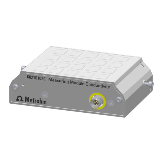
■■■■■■■■■■■■■■■■■■■■■■ Functional description 3 Functional description Measuring Module Conductivity – Overview Figure 1 Measuring Module Conductivity – Overview Fastening screws Measuring input For conductivity measuring cell (see Measur- ing Module Conductivity – Connector speci- fications, page Status display LED (green-red) Various conductivity measuring cells with integrated temperature sensor can be connected to the measuring input of the Measuring Module Con- ductivity, see... -
Page 16: System - Signals
System – Signals ■■■■■■■■■■■■■■■■■■■■■■ System – Signals System components with status indicators show their operating status with colors and/or flashing patterns. The meaning of the colors and flash- ing patterns is explained in the following table. Visual signal Meaning LED lights up yellow. System start or initialization LED flashes yellow (slowly). -
Page 17: Delivery And Packaging
■■■■■■■■■■■■■■■■■■■■■■ Delivery and packaging 4 Delivery and packaging Delivery Inspect the delivery immediately upon receipt: Check the delivery against the delivery note to ensure completeness. ■ Check the product for damage. ■ If the delivery is incomplete or damaged, contact your regional Met- ■... -
Page 18: After Installation
Mounting the measuring module ■■■■■■■■■■■■■■■■■■■■■■ 5 After installation Mounting the measuring module The measuring module is supplied with mounted fastening screws. These fastening screws are used to secure the measuring module in the instru- ment to ensure trouble-free operation. 1 Opening the lid Open the lid. - Page 19 ■■■■■■■■■■■■■■■■■■■■■■ After installation Push the side covering upwards until it can be removed from the ■ side. Remove the side covering to the side. ■ 3 Removing the fastening screws Remove the 2 fastening screws from the measuring module using ■...
- Page 20 Mounting the measuring module ■■■■■■■■■■■■■■■■■■■■■■ 5 Attaching the measuring module Insert the fastening screws. Tighten the measuring module to the ■ housing from both sides using the hex key. 6 Mounting the side parts Carry out the following steps on both sides of the instrument. Position the side covering from the side in an elevated position.
-
Page 21: Connecting The Sensor
■■■■■■■■■■■■■■■■■■■■■■ After installation Connecting the sensor 1 Plugging in the electrode cable Open the lid of the instrument. ■ Align the red dot on the plug with the groove on the connection ■ socket. Plug in the plug of the electrode cable until you can feel it snap in. ■... -
Page 22: Operation And Control
Operation ■■■■■■■■■■■■■■■■■■■■■■ 6 Operation and control Operation The product can be operated via the OMNIS Software. Further information on the OMNIS Software under OMNIS Help. ■■■■■■■■... -
Page 23: Maintenance
Metrohm recommends having the products maintained by specialist ■ personnel of Metrohm AG as part of an annual service. Shorter mainte- nance intervals may be necessary if you frequently work with caustic and corrosive chemicals. - Page 24 Protect live components (e.g. power supply unit, power cord, con- ■ nection sockets) against moisture. Always have maintenance work and repairs on electrical compo- ■ nents carried out by a regional Metrohm service representative. Prerequisite: The product is switched off and disconnected from the energy supply. ■ Required accessories: Cleaning cloth (soft, lint-free) ■...
-
Page 25: Troubleshooting
■■■■■■■■■■■■■■■■■■■■■■ Troubleshooting 8 Troubleshooting Messages on malfunctions and errors are displayed in the control software or in the embedded software (e.g. on the display of an instrument) and contain the following information: Descriptions of causes of malfunctions (e.g. jammed drive) ■... - Page 26 ■■■■■■■■■■■■■■■■■■■■■■ 9 Disposal Properly dispose of chemicals and of the product to reduce negative effects on the environment and public health. Local authorities, waste dis- posal companies or dealers provide more detailed information on disposal. Observe the WEEE EU directive (WEEE = Waste Electrical and Electronic Equipment) for the proper disposal of waste electronic equipment within the European Union.
-
Page 27: Technical Specifications
■■■■■■■■■■■■■■■■■■■■■■ Technical specifications 10 Technical specifications 10.1 Ambient conditions Nominal function range +5 to +45 °C at max. 80% relative humidity, non- condensing Storage +5 to +45 °C 10.2 Measuring module – Energy supply Power consumption max. 0.6 W Energy transmission inductive coupling 10.3 Measuring module –... -
Page 28: Measuring Module - Housing
Measuring module – Housing ■■■■■■■■■■■■■■■■■■■■■■ 10.4 Measuring module – Housing Materials AW-5754 H12 / H22 aluminum, coated Back panel poly(butylene tereph- thalate) GD-ZnAl4Cu1 zinc die cast, nickel- Enclosure plated IP degree of protection IP 40 10.5 Measuring Module Conductivity – Connector specifi- cations Conductivity socket Socket... -
Page 29: Measuring Module Conductivity - Measurement Specifications
■■■■■■■■■■■■■■■■■■■■■■ Technical specifications 10.7 Measuring Module Conductivity – Measurement specifications Conductivity Measuring range 0.1 µS–1,000 mS Resolution significant digits Measuring accuracy ±0.5% ±1 digit in the measuring range 0.1 µS–16 µS ±0.5% ±1 digit in the measuring range 16 µS–1,000 µS ±1% ±1 digit in the measuring range 1,000 µS–1,000 mS...
Need help?
Do you have a question about the 6.02101.020 and is the answer not in the manual?
Questions and answers