Advertisement
Quick Links
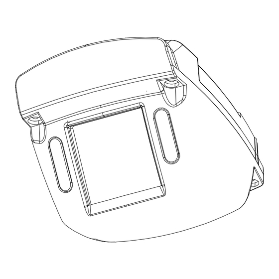
8. Replace Camera Housing
1. Close the housing back over onto the base.
2. Use the security key to tighten the four captive locking
screws. See Figure 2.
Specifications
Power Consumption
7 W max. @ 12 VDC
Operating Voltage Range
9 to 14 VDC (powered by DVR)
Operating Temperature Range
-40 to 140°F (-40 to 60°C)
Horizontal Resolution
700 TV Lines
Infrared LED Lamps
4 high efficiency LEDs
Minimum Illumination
0.061 lux at F2.0
0 lux (IR on)
Enclosure Size, LxWxH
5.16" (131 mm) x 3.45 " (88 mm) x 3" (77 mm)
Enclosure Material
Solid aluminum alloy, powder-coated
Window
Impact-resistant polycarbonate, scratch-resistant, UV protected
Connector Cable length
9.5" (24.1 cm)
Weight
1.22 lbs (554 g)
Routine Maintenance
Most liquid cleaners or graffiti gel can be used to clean
your camera enclosure. Do not use abrasive cleaners
that can scratch the window and reduce visibility of the
camera.
Warranty
For full warranty information, go to
https://www.safefleet.net/documents/Seon-Warranty.pdf
Service
If your CA10 Wedge Camera is to be returned for service, please contact the Safe Fleet technical support team, provide the model and/
or serial# of your unit, and ask for a Return Merchandise Authorization (RMA) number. An RMA# allows the support team to better
track your product when it comes in for service. Please show the RMA# on the outside of the package.
ANY PRODUCT SENT WITHOUT AN RMA# MAY BE REFUSED!
Technical Support
Documentation
Additional copies of this guide, along with other supporting documentation can be found on
•
Email: PTsupport@safefleet.net
the SafeFleet Community (https://community.safefleet.net)
•
Phone: 1.844.899.7366
Information in this guide is subject to change without notice.
CAUTION: Do Not Pinch Safety Wire
Ensure closing the cover does not pinch the wire
connecting the cover to the base. This can allow
moisture to enter and damage the unit.
Replacing a Damaged Camera
If the camera window is damaged or scratched, order a
replacement camera from your distributor. To remove
and replace the housing, follow the steps in section 3
Open the Camera and section 8 Replace Camera Hous-
ing.
For any other inquiries to address camera damage, con-
tact the Safe Fleet Technical Support Team..
Installation Kit Contents
•
1x CA Series wedge
•
1x security key
camera
•
1x Drilling template
•
3x #10 3/4" Phillips
screws
1. Choose Camera Location
1. Select a flat location to minimize possible moisture
leakage into the vehicle. Cameras must be installed
with the cabling running inside the wall panels.
2. Use the supplied drilling guide template to mark the
cable (7/8") and screw (5/32") holes on the panel.
3. Use a step-bit to drill the cable hole, and regular
bits for the screw holes.
2. Connect the Camera
1. Connect the camera cable to the
extension cable through the panel cable
hole. See Figure 1.
2. Connect the extension cable's 2×3
Micro-Fit connector into a Digital Video
Recorder (DVR).
3. Open the Camera
1. Using the security key supplied with the camera, loosen
the four captive screws on the housing. See Figure 2.
2. Lift the housing off of the base.
Wedge Camera CA10
Quick Installation Guide
TIP: Seal the Camera Mounting Holes
For outdoor installations, if a flat surface is not avail-
able, carefully seal the mounting holes under the base
of the camera after installation. Do NOT apply silicone
or other sealants around the base of the camera.
TIP: Cover and base are connected
Do not strain the LED and ground wires connecting the
cover to the base. Damage to the camera can occur.
When the camera cover is open, take care to ensure it
does not flop against the vehicle surface. Damage to
paint can occur.
© Safe Fleet | 2024 | All rights reserved | Part #: 700-1068 R4
Figure 1
Advertisement

Subscribe to Our Youtube Channel
Related Manuals for Safe Fleet CA Series


Summary of Contents for Safe Fleet CA Series
- Page 1 See Figure 2. If your CA10 Wedge Camera is to be returned for service, please contact the Safe Fleet technical support team, provide the model and/ cover to the base. Damage to the camera can occur.
- Page 2 3. Open the Camera 6. Aim the Camera (continued) IMPORTANT: Tilt Adjustment Screws To get the required video image, adjust the camera‘s rotation, 1: Top lid assembly Figure 2 pan, and tilt settings using the adjustment controls shown in Do not attempt to adjust gimbal rotation or tilt 2: Captive housing screws Figure 4 and described in the following steps: before loosening the adjustment screws on the...
Need help?
Do you have a question about the CA Series and is the answer not in the manual?
Questions and answers