Table of Contents
Advertisement
Quick Links
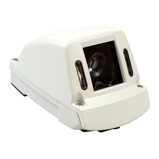
HD3W Wedge Camera
Quick Installation Guide
© Seon Design Inc. | January 2017 | All rights reserved.
www.seon.com Part Number: 700-1081 R2
*700-1068*
WARNING: Cable Compatibility
This camera requires a special Analog High Definition (AHD) cable - as
indicated by a blue band in front of the connectors. Note that a
standard cable may appear to work on a small analog screen, but the
image will be significantly degraded during subsequent playback.
Installation Kit Contents
•
1 HD3W wedge camera
•
3 #10 3/4" Phillips screws
•
1 security key
•
1 Quick Installation Guide
•
1 Drilling template
1. Choose Camera Location
1.
Determine the location for mounting the camera. Select a flat
location to minimize possible moisture leakage into the vehicle.
INSTALL TIP: Seal the camera mounting holes
For outdoor installations, if a flat surface is not available, carefully seal
the mounting holes under the base of the camera after installation. Do
NOT apply silicone or other sealants around the base of the camera.
Cameras must be installed with the cabling running inside the wall
panels.
2.
Use the supplied drilling guide template to mark the cable (7/8")
and screw (5/32") holes on the panel.
3.
Use a step-bit to drill the cable hole, and regular bits for the screw
holes.
2. Connect the Camera
1.
Connect the camera cable to the extension cable through the
panel cable hole. See Figure 1.
Important: ensure the extension cable has a blue band in front of
the connectors, indicating it is AHD (Analog High Definition)-com-
patible.
2.
Connect the extension cable's 2×3 Micro-Fit connector into a
digital video recorder (DVR).
Figure 1
3. Open the Camera
1.
Using the security key supplied with the camera, loosen the four
captive screws on the housing. See Figure 2.
2.
Lift the housing off of the base.
CAUTION: Housing can scratch vehicle
When the camera cover is open, take care to ensure it does not flop
against the vehicle surface. Damage to paint can occur.
Figure 2
Camera housing
Captive housing
screws
LED and Ground
connection wires
Camera gimbal
Menu Button
Local Video Out
Base
4. Install the Camera
INSTALL TIP: Camera PCB and Wiring
While installing the camera, do not impact the printed circuit board or
wiring inside the camera with screws or screwdriver bits.
Damage to the camera can occur.
Use the three #10×3/4" mounting screws supplied with the camera to
attach the camera to a wall or ceiling. See Figure 3.
The mounting gaskets on the camera base seal the screw and cable
holes when mounted on a flat surface.
INSTALL TIP: Allow Camera Ventilation
The camera is designed to vent for proper operation. Do NOT apply
silicone or other sealants around the base of the camera.
5. View Camera Output
1.
Power on the DVR and camera.
2.
Connect the supplied local video out adapter cable's 3.5mm audio
plug to the camera's Local Video Out socket. See the image in
section 3.
3.
Connect the local video out cable's RCA end to a video monitor to
see the camera's line of view while adjusting the camera's rotation,
pan, and tilt positions.
Figure 3
Mounting gasket
Base
(Do not
apply
sealant
around
base)
#10x3/4"
mounting
screws
Advertisement
Table of Contents

Subscribe to Our Youtube Channel
Related Manuals for Safe Fleet SEON HD3W


Summary of Contents for Safe Fleet SEON HD3W
- Page 1 3. Open the Camera Using the security key supplied with the camera, loosen the four captive screws on the housing. See Figure 2. HD3W Wedge Camera Lift the housing off of the base. CAUTION: Housing can scratch vehicle Quick Installation Guide When the camera cover is open, take care to ensure it does not flop against the vehicle surface.
- Page 2 6. Aim the Camera 8. Replace Camera Housing To get the required video image, adjust the camera‘s rotation, pan, and Close the housing back over onto the base. tilt settings using the adjustment controls shown in Figure 4 and CAUTION: Do not pinch safety wire described in the following steps: Ensure closing the cover does not pinch the wire connecting the cover to the base.
Need help?
Do you have a question about the SEON HD3W and is the answer not in the manual?
Questions and answers