
Subscribe to Our Youtube Channel
Related Manuals for Meiko M-iClean PF


Summary of Contents for Meiko M-iClean PF
- Page 1 MEIKO M-iClean PF Utensil washer Installation instructions For the types in the series: M009DWFL10M1-**** Read before assembling the machine! test 9022337 / Valid from: 2022-04 / Update: 2023-06 www.meiko.info...
-
Page 2: Table Of Contents
Contents NOTICE REGARDING INSTALLATION INSTRUCTIONS ........... 3 Product identification Presentation conventions 1.2.1 Safety symbols in the instructions SAFETY ........................4 General safety instructions TRANSPORT ........................ 5 Checking the condition at delivery Unpacking TECHNICAL DATA ....................... 6 DIMENSIONAL DRAWINGS AND CONNECTION DIMENSIONS ....... 7 INSTALLATION ...................... -
Page 3: Notice Regarding Installation Instructions
Notice regarding installation instructions Product identification These installation instructions are valid for the product series MEIKO M-iClean PF (M009DWFL1M1-10). Presentation conventions Warnings DANGER – indicates an imminently hazardous situation which, if not avoided, will result in serious injury or death. -
Page 4: Safety
Where discharge currents exceed 10 mA, the use of an RCD is not recom- mended. False alarms restrict machine availability. MEIKO expressly excludes any liabil- ity for damages caused by improper connection of the machine. This includes any costs in connection with services due to said connection, e.g. -
Page 5: Transport
Check the machine for transportation damage. Note If there is any suspicion of transportation damage, the shipping company and MEIKO must be informed immediately in writing. Photograph any damaged parts and send the pictures to MEIKO. 9022337 5 / 30... -
Page 6: Unpacking
Storage temperature 5–40°C Maximum height of the installation site above 2000 m sea level Net weight M-iClean PF-S 226 kg Noise emission ≤ 70 dB (A) Noise level in the workplace LpA GiO MODULE Dimensions (W x D x H) -
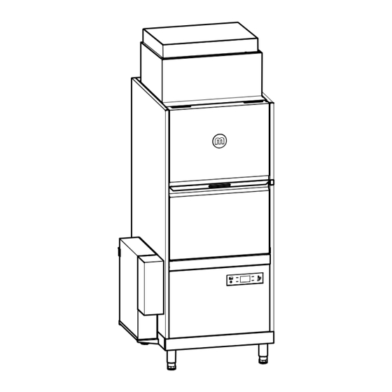
Page 7: Dimensional Drawings And Connection Dimensions
Dimensional drawings and connection dimensions MEIKO M-iClean PF-S Standard and solid substance dosing option Max. 500 (door folded down) Max. 2369 (door folded down) Entry height Fresh water supply line Drain Electrical supply pipe to the machine Connection for solid detergent detergent dosing unit on site (optional) - Page 8 MEIKO M-iClean PF-S with AirConcept (heat recovery) Max. 500 (door folded down) Max. 2369 (door folded down) Entry height Fresh water supply line Drain Electrical supply pipe to the machine Separation Installation clearance 8 / 30 9022337...
- Page 9 MEIKO M-iClean PF-S with GiO MODULE (optional) Max. 500 (door folded down) Max. 2369 (door folded down) Entry height Fresh water supply line Drain Electrical supply pipe to the machine GiO MODULE on bracket (W x D x H) 143 x 660 x 600 mm Country-specific deviations are possible.
-
Page 10: Installation
Installation Requirements to the electrical connection • Electrical connection must be carried out in accordance with the locally applicable regulations (e.g. HD 60364-1/IEC 60364-1/VDE 0100-100) so the machine can be connected to the mains supply in accordance with the installer's regulations. How- ever, national installer's regulations may differ. -
Page 11: Requirements For The Fresh Water Connectionrequirements For The Fresh Water Connection
Electrical connection Mains connection terminal 5-pin (with neutral conductor) strip 4-pin (without neutral conductor) Special national USA/Canada: conditions The machine must be installed in accordance with local regulations. In the absence of any such regulations, install the machine in accordance with the applicable requirements in the National Electrical Code, NFPA 70, Cana- dian Electrical Code (CEC), Part 1, CSA C22.1 and the Standard for Venti- lation Control and Fire Protection of Commercial Cooking Operations,... -
Page 12: Requirements For The Waste Water Connection
Fresh water limit values when operating a reverse osmosis module Designation Value 70 – 1000 µS/cm Conductivity 0 – 28 °dH Water hardness Feed water temperature Min. 1°C to max. 35°C (cold water connection) Minimum flow pressure 100 kPa (1 bar) Maximum pressure 500 kPa (5 bar) Free from particles... -
Page 13: Assembly
Assembly Align machine feet 1. Place the machine at its destination using the pallet jack. 2. Relieve the pressure on the foot and adjust it to 3. To adjust the foot, use a short spanner with a the desired height using a suitable spanner. Do width across flats of 50. -
Page 14: Fit Airconcept (Heat Recovery)
Fit AirConcept (heat recovery) 1. Place the heat exchanger unit on the dishwash- 2. Secure the heat exchanger unit with 4 M5 safety ing machine and insert the threaded bolts on the nuts. dishwashing machine through the holes in the heat exchanger unit. - Page 15 7. Fit the electrical box on the right side and insert 8. Secure the electrical box with 2 M5 safety nuts. the threaded bolts through the holes in the elec- trical box. 9. Fit the solenoid valve on the back and pass the 10.
- Page 16 12. Lay the cables on the machine according to the cable length and secure them with the enclosed clamps. 13. Attach the protective conductor on the front with connection plan Z. 14. Slide in the heat exchanger unit casing from the 15.
- Page 17 16. Slide the 7 clips onto the holes in the casing for the fan unit. 17. Push in the fan unit casing from the front. Secure the casing with 4 self-tapping screws per side and 2 self-tapping screws on the front. 18.
-
Page 18: Connect Dosing Pipes
Connect dosing pipes The connections for detergent (white), rinse aid (blue) and the third dosing agent (optional) are located in the middle at the bottom of the back of the machine (1). 1. Connect the hoses with the suction lances according to the colours and secure them with a collar clamp. 2. -
Page 19: Install Solid Substance Dosing (Optional)
Install solid substance dosing (optional) Note • The dosing point can be attached on the left or right side of the machine. The attachment for the right side is shown below as an example. When mounted on the left side, the representations are to be understood as mirror images. •... - Page 20 Position of the electrode to measure conductivity Install dosing point 1. Select the side for the dosing point. 2. Remove the side wall. 3. Place the rectangular cut-out on the side wall. To 4. Drill the hole for the dosing connection on the easily separate the cut-out, drill a Ø...
-
Page 21: Connect External Gio Module (Optional)
8. Weld on the 2 threaded bolts (M5x8). 9. Mount the cover plate with washer and cap nut (M5). Attach the 90° hose connection. 10. Remove the tank cover sieve and the filter. 11. Drill the hole for the measuring electrode at the tank bottom. The hole diameter may change depending on the conductivity probe to be installed. - Page 22 Mounting on retaining plate 1. Loosen the 6 screws of the cover of the GiO MODULE and carefully remove the cover. The protective conductor is mounted on the inside of the cover. Make sure that the cable is not dam- aged.
- Page 23 7. Connect the equipotential bonding. 8. Tighten the hoses from the outside and attach the cover. 9. Break out the holes in the base drip tray for the 10. Insert the reinforcement profile from the inside into the base drip tray and insert the welded hexagon reinforcement profile (see picture).
- Page 24 14. Place the GiO MODULE on the plinth and align 15. Position the holding bracket. Distance from the top edge of the GiO MODULE: 70 mm. 16. Drill out the holding bracket on the side wall. 17. Screw the holding bracket with M5 hexagon screws, washers and self-locking nuts. 18.
- Page 25 Freestanding assembly 1. Loosen the 6 screws of the cover of the GiO MODULE and carefully remove the cover. The protective conductor is mounted on the inside of the cover. Make sure that the cable is not dam- aged. 2. Guide the fresh water supply line (4) and the transparent fabric hoses for permeate recirculation (1), per- meate (3) and concentrate (2) through the side opening in the casing.
- Page 26 7. Connect the equipotential bonding. 8. Place the GiO MODULE on the foot and insert the welded hexagon screws on the foot into the holes on the underside of the GiO MODULE. 9. Place the perforated rail and the 2 washers on 10.
-
Page 27: Connection
Commissioning Once all connections are in place, request a service technician authorised by MEIKO for the handover. This person must check the entire installation and carry out commissioning. Subse- quently, the operating personnel is instructed on the basis of the handover protocol. -
Page 28: Index
Safety symbols in the instructions ......3 Designation of machine type ......... 3 Dimensional drawings ..........7 Technical data ............6 M-iClean PF-S Standard and solid substance dosing option ..................7 M-iClean PF-S with AirConcept (heat recovery) ....8 Unpacking ..............6 M-iClean PF-S with GiO MODULE (optional) ...... 9... - Page 29 …………………………………………………………………………… …………………………………………………………………………… …………………………………………………………………………… …………………………………………………………………………… …………………………………………………………………………… …………………………………………………………………………… …………………………………………………………………………… …………………………………………………………………………… …………………………………………………………………………… …………………………………………………………………………… …………………………………………………………………………… …………………………………………………………………………… …………………………………………………………………………… …………………………………………………………………………… …………………………………………………………………………… …………………………………………………………………………… …………………………………………………………………………… …………………………………………………………………………… …………………………………………………………………………… …………………………………………………………………………… …………………………………………………………………………… …………………………………………………………………………… …………………………………………………………………………… …………………………………………………………………………… …………………………………………………………………………… …………………………………………………………………………… …………………………………………………………………………… …………………………………………………………………………… …………………………………………………………………………… …………………………………………………………………………… …………………………………………………………………………… …………………………………………………………………………… …………………………………………………………………………… …………………………………………………………………………… 9022337 29 / 30...
- Page 30 MEIKO Maschinenbau GmbH & Co. KG Englerstraße 3 77652 Offenburg Germany www.meiko-global.com info@meiko-global.com Design and construction subject to change without prior notice! 9022337 / Valid from: 2022-04 / Update: 2023-06...
Need help?
Do you have a question about the M-iClean PF and is the answer not in the manual?
Questions and answers