Advertisement
WIRING DIAGRAM
 *Note: The manual may update without prior notice. Please download the latest version of original files in this manual
INSTALLATIONS
BEFORE YOU BEGIN, READ THE FOLLOWING INSTRUCTIONS COMPLETELY AND CAREFULLY.
INSTALLING

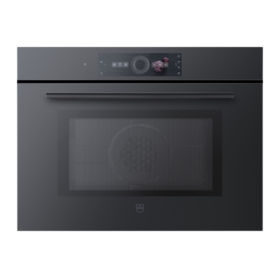
- Empty the microwave oven and clean inside it with a soft, damp cloth. Check for damage such as misaligned door, damage around the door or dents inside the cavity or on the exterior.
- Put the oven on a counter, table, or shelf that is strong enough to hold the oven with the food and utensils you put in it. (The control panel side of the oven is the heavy side. Use care when handling.)
- Do not block the vent and the air intake openings. Blocking vent or air intake openings can cause damage to the oven and poor cooking results. Make sure the microwave oven legs are in place to ensure proper air flow.
- The oven should not be installed in any area where heat and steam are generated, because they may damage the electronic or mechanical parts of the unit.
- Use microwave oven in an ambient temperature less than 104°F(40°C).
Note: The figure above is shown as a sample, for specific model please refer to the instruction manual.
EARTHING INSTRUCTIONS
This microwave oven is designed to be used in a fully earthed condition. It is imperative, therefore, to make sure it is properly earthed before servicing

THIS APPLIANCE MUST BE EARTHED

The wires in this mains lead are colored in accordance with the following code:
| Green-and-yellow: | Earth |
| Blue: | Neutral |
| Brown: | Live |
As the colors of the wires in the mains lead of this appliance may not correspond with the colored markings identifying the terminals in your plug, proceed as follows. The wire which is colored green-and-yellow must be connected to the terminal in the plug which is marked with the letter E or by the earth symbol (![]() ) or colored green or green-and-yellow. The wire which is colored blue must be connected to the terminal in the plug which is marked with the letter N or colored black. The wire which is colored brown must be connected to the terminal in the plug which is marked with the letter L or colored red.
) or colored green or green-and-yellow. The wire which is colored blue must be connected to the terminal in the plug which is marked with the letter N or colored black. The wire which is colored brown must be connected to the terminal in the plug which is marked with the letter L or colored red.
SERVICE INFORMATION
TOOLS AND MEASURING INSTRUMENTS
NECESSARY TOOLS
Tools normally used for TV servicing are sufficient.
Standard tools are listed below.
- Diagonal pliers
- Long nose pliers
- Phillips screwdriver
- Flat blade screwdriver
- Wrench (size 5mm)
- Nut driver (size 5mm)
- Adjustable wrench
- Soldering iron
- Solder
- Vinyl insulation tape
- Polishing cloth
NECESSARY MEASURING INSTRUMENTS
- TESTER(VOLTS-DC, AC., Ohmmeter)
- Microwave survey meter
- Holaday HI-1500 HI-1501
- Narda 8100
8200
- Inch scale
- 600 cc non conductive material beaker (glass or plastic), inside diameter: approx. 8.5 cm (31/2 in.)
- Cylindrical and made of borosilicate glass vessel.
max. thickness: 3 mm
outside diameter: approx. 190mm
height: approx. 90mm - Glass thermometer: 100°C or 212°F (1 deg scale)
MICROWAVE LEAKAGE TEST

- Be sure to check microwave leakage prior to servicing the oven if the oven is operative prior to servicing.
- The service personnel should inform the manufacture importer, or assembler of any certified oven unit found to have a microwave emission level in excess of 5 mW/cm2 and should repair any unit found to have excessive emission levels at no cost to the owner and should ascertain the cause of the excessive leakage. The service personnel should instruct the owner not to use the unit until the oven has been brought into compliance.
- If the oven operates with the door open, the service personnel should:
- Tell the user not to operate the oven.
- Contact the manufacturer.
- The service personnel should check all surface and vent openings for microwave leakage.
- Check for microwave leakage after every servicing. The power density of the microwave radiation leakage emitted by the microwave oven should not exceed 4 mW/cm2. Always start measuring of an unknown field to assure safety for operating personnel from radiation leakage.
MEASURING MICROWAVE ENERGY LEAKAGE
- Pour 275±15cc of 20±5°C(68±9°F) water in a glass container which is graduated to 600 cc, and place the container on the center of the turntable.
- Set the energy leakage monitor to 2450 MHz and use it following the manufacturer's recommended test procedure to assure correct result.
- When measuring the leakage, always use the 2- inch (5cm) spacer supplied with the probe.
- Operate the oven at its maximum output.
- Measure the microwave radiation using and electromagnetic radiation monitor by holding the probe perpendicular to the surface being measured
Move probe along shaded area
Probe scanning speed
Less than 2.5 cm/sec
(1 inch/sec)
![]()

MEASUREMENT WITH OUTER CASE REMOVED
- When you replace the magnetron, measure for microwave energy leakage before the outer case is installed and after all necessary components are replaced or adjusted.
Special care should be taken in measuring the following parts. (Circled area of below Fig.)- Around the magnetron
- The waveguide

AVOID CONTACTING ANY HIGH VOLTAGE PARTS

MEASUREMENT WITH A FULLY ASSEMBLED OVEN
- After all components, including the outer case, are fully assembled, measure for microwave energy leakage around the door viewing window, the exhaust opening, and air inlet openings.
- Microwave energy leakage must not exceed the values prescribed below.
NOTE: Leakage with the outer case removed less than 5 mW/cm 2. Leakage for a fully assembled oven (Before the latch switch (primary) is interrupted) with the door in a slightly opened position-less than 2 mW/cm . 2
NOTES WHEN MEASURING
- Do not exceed meter full scale deflection.
- The test probe must be moved no faster than 1 inch/sec (2.5 cm/sec) along the shaded area, otherwise a false reading may result.
- The test probe must be held with the grip portion of the handle.
A false reading may result if the operator's hand is between the handle and the probe. - When testing near a corner of the door, keep the probe perpendicular to the surface making sure the probe horizontally along the oven surface, this may possibly cause probe damage.
RECORD KEEPING AND NOTIFICATION AFTER MEASUREMENT
- After adjustment and repair of any microwave energy interruption or microwave energy blocking device, record the measured values for future reference. Also enter the information on the service invoice.
- The microwave energy leakage should not be more than 4 mW/cm 2 . after determining that all parts are in good condition, functioning properly and genuine replacement parts which are listed in this manual have been used.
- At least once a year, have the electromagnetic energy leakage monitor checked for calibration by its manufacturer.
DISASSEMBLY AND ADJUSTMENT
- OUTER COVER REMOVAL

- Loose screws on top and take out the top outer cover.
- Turn to the backside, loose screws and take out the back one.
- Loose screws on both sides, then take out the left and right one in turn.

- DOOR ASSEMBLY AND CONTROL PANEL ASSEMBLY REMOVAL


- Open the door to 90°, lift up the hinge lock and put it down.
- Close the door to 30°, lift up the whole door assembly slightly and take it out.
- Disconnect the wires connected to the PCB.
- Loose the screws fixed on the bracket.
- Take out the control panel assembly.
- FAN ASSEMBLY REMOVAL

- Loose screws and take out the wind guide cover.
- Then remove the fan.

- ELECTRICAL PARTS REMOVAL
- Loose screws and remove the H.V. transformer.
- Then the magnetron. Also take out the thermostat and its bracket on top.
- Remove the metal bracket next to the magnetron.
- Release the capacitor bracket. Take out the capacitor and remove the H.V. diode.
- Loose screws and remove the motor.

- Loose screw fixed on the filter bracket. Then take out the filter.
- Remove the interlock assembly on both sides.


- TOP INSULATED PLATE REMOVAL

- Remove the LED bulb first.
- Then loose screws and take out the top insulated plate.
- Take out the metal cover.

- CONVECTION ASSEMBLY REMOVAL
![]()
- Loose screws and take out the heater cover.
- Then take out the heater inside.
- Loose the nut and take out the convection fan.

- POWER BOARD REMOVAL

- Turn around the whole unit.
- Loose screws and take out the convection motor.
- Disconnect the wires leading to the power board.
- Loose screws and remove the power board and its bracket.

- BOTTOM PLATE REMOVAL

- Take out the hanging brackets on both sides
- Turn over the whole unit.
- Loose screws fixed between bottom plate and backside insulated plate.
- Remove the insulated plate.
- Loose the other screws on bottom plate. Then take it out.
- Also take out the defrosting pan below.

- HEATERS AND STIRRIER ASSEMBLY REMOVAL

- Loose screws inside the cavity and nuts on backside. Then take out the top heater.
- The bottom heater is the next one.
- Loose screws fixed on the splash cover and remove it.
- Take out the stirrer assembly and disassemble it.

DOOR ASSEMBLY
- Remove the door gasket and seal ring

- Remove the door frame and remove the hinge

- Take out the insulation glass, loose screws and remove the handle assembly


CONTROL PANEL DISASSEMBLY
- Disconnect the wires and remove the power PCB
- Remove screws holding operating panel cover
- Remove control PCB and other electrical components
INTERLOCK CONTINUITY TEST
FOR CONTINUED PROTECTION AGAINST EXCESSIVE RADIATION EMISSION, REPLACE ONLY WITH IDENTICAL REPLACEMENT PARTS. TYPE NO. KW3A FOR SWITCHES
PRIMARY INTERLOCK SWITCH TEST
When the door release button is depressed slowly with the door closed, an audible click should be heard at the same time or successively at intervals. When the button is released slowly, the latches should activate the switches with an audible click. If the latches do not activate the switches when the door is closed, the switches should be adjusted in accordance with the adjustment procedure. Disconnect the wire from the primary switch. Connect the ohmmeter to the common (COM) and normally open (NO) terminal of the switch. The meter should indicate an open circuit in the door open condition. When the door is closed, the meter should indicate a closed circuit. When the primary switch operation is abnormal, make the necessary adjustment or replace the switch with the correct spare part.
SECONDARY INTERLOCK SWITCH TEST
Disconnect the wire from the secondary switch. Connect the ohmmeter to the common (COM) and normally open (NO) terminals of the switch. The meter should indicate an open circuit in the door open condition. When the door is closed, ohmmeter should indicate a closed circuit. When the secondary switch operation is abnormal, make the necessary adjustment or replace the switch with the correct spare part.
MONITOR SWITCH TEST
Disconnect the wire from the monitor switch. Connect the ohmmeter to the common (COM) and normally closed (NC) terminals of the switch. The ohmmeter should indicate closed circuit in the door open condition. When the door is closed, meter should indicate an open circuit. When the monitor switch operation is abnormal, replace with the correct spare part.
NOTE: After repairing the door or the interlock system, it is necessary to repeat the interlock switch tests before operating the appliance.
| COMPONENTS | TEST PROCEDURE | RESULTS | ||
| SWITCHES (Wires disconnected) | Check for continuity of the switch with an Ohm-meter | Door open | Door closed | |
| Primary Switch Type No. KW3A |  |  |  | |
| Monitor Switch Type No. KW3A |  |  |  | |
| Secondary Switch Type No. KW3A |  |  |  | |
| NOTE: After checking for the continuity of switches, make sure that are correctly connected. | ||||
COMPONENT TEST PROCEDURE
- DISCONNECT THE POWER SUPPLY CORD FROM THE OUTLET WHENEVER REMOVING THE OUTER CASE FROM THE UNIT. PROCEED WITH THE TEST ONLY AFTER DISCHARGING THE HIGH VOLTAGE CAPACITOR AND DISCONNECTING THE WIRE FROM THE PRIMARY WINDING OF THE HIGH VOLTAGE TRANSFORMER.
- ALL OPERATIONAL CHECKS WITH MICROWAVE ENERGY MUST BE DONE WITH A LOAD (1 LITER OF WATER IN A GLA S S CONTAINER) IN THE OVEN.
| COMPONENTS | TEST PROCEDURE | RESULTS |
| HIGH VOLTAGE TRANSFORMER (Wires disconnected) | 
| Approx.: 1.4 ohm Approx.: 90 ohm Less than: 1 ohm Normal: Infinite Normal: Infinite |
| MAGNETRON (Wires disconnected) |
| Normal: Less than 1 ohm Normal: Infinite |
 NOTE: When testing the magnetron, be sure to install the magnetron gasket in the correct position and be sure that the gasket is in good condition. | ||
| HIGH VOLTAGE CAPACITOR | Measure the resistance. (Ohmmeter scale: Rx1000)
| Normal: Momentarily indicates several ohms, and then gradually returns to 10M ohms. |
Measure the resistance. (Ohmmeter scale: Rx1000)
| Normal: ∞ | |
| HIGH VOLTAGE DIODE *NOTE: Some inexpensive meters may indicate infinite resistance in both directions. | Measure the continuity (Forward). (Ohm-meter scale: Rx10000)  | Normal: Continuity. Abnormal: ∞ * |
| Measure the continuity (Reverse). (Ohm-meter scale: Rx10000)  | Normal: ∞ Abnormal: Continuity. |


| COMPONENTS | TEST PROCEDURE | RESULTS | |
| FUSE | Check for continuity of the fuse with a multi-meter. | Normal | Abnormal |
 |  | ||
| NOTE: If the fuse is blown, check the primary, the secondary, and the monitor switches, H.V.D. and H.V.C. before replacing the fuse. If the fuse is blown by improper switch operation replace the defective switch and the fuse at the same time. Replace just the fuse if the switches operate correctly. | |||
| HEATER ELEMENT (Wires disconnected) | Measure the resistance. (Multi-meter scale: Rx1)  | Normal: *Grill heater Approx. 38 ohm (at 20 ~ 30°C) | |
Measure the resistance with 500V-100M ohm insulation resistance meter. | Normal: more than 0.5 Mohm | ||
| NOTE: Make sure heater is fully cooled when tested. | |||
| THERMAL CUT-OUT |  | Below specified temperature | Above specified temperature |
 |  | ||
| COMPONENTS | TEST PROCEDURE | RESULTS | |
| L.V.Transformer of PCB (Refer to schematic diagram) | Check for PCB connector. *Disconnect the 3-pin connector from P.C.B.  | Normal | Abnormal |
 |  | ||
| RELAY 2, RELAY 3 OF P.C.B. (Wires disconnected) Note: Relay Relay 1: Fan motor Turntable motor Oven lamp Relay 2: Microwave Relay 3: Grill |  | Cooking start | OFF |
 |  | ||
| FAN MOTOR (Wires disconnected) | Measure the resistance. (Ohm-meter scale: R x 1)  | Normal: 100~500 Ω Abnormal: ∞ or several Ω | |
| TURNTABLE MOTOR (Wires disconnected) | Measure the resistance. (Ohm-meter scale: R x 1000)  | Normal: Approx.100~200KΩ Abnormal: ∞ or several Ω | |
NOTE:
| |||
TROUBLE SHOOTING
WHEN RECEIVING A COMPLAINT FROM A CUSTOMER, EVALUATE THE COMPLAINT CAREFULLY. IF THE FOLLOWING SYMPTOMS APPLY, PLEASE INSTRUCT THE CUSTOMER IN THE PROPER USE OF THE MICROWAVE OVEN. THIS CAN ELIMINATE UNNECESSARY SERVICE CALLS.
- Check grounding before checking for functional issues.
- Be careful of the high voltage circuit.
- Discharge the high voltage capacitor.
- When checking the function of switches or of high voltage transformer, disconnect one wire from these parts and then check continuity with the AC plug removed. To do otherwise may result in a false reading or damage to your diagnostic equipment.
- Do not touch any circuits on PCBs since static electric discharge may damage the control panel. Always ground yourself while working on this panel to discharge any static charge built up in your body.
| CONDITION | CAUSE | REMEDY |
Built-in Compact oven does not work | Inserting many plug into one plug outlet and using them at the same time (causes overloading). | Avoid using other electrical appliances when you use the microwave oven. |
| Microwave oven plug is not inserted tightly. | Insert microwave oven plug securely. | |
Output power is too low | Low AC input voltage. | Use the microwave oven at adequate line voltage. |
| Food temperature is too low. | This may not be a defect. It is possible that the food should be cooked for a longer time period. | |
Sparks occurring | Using metallic ware and touching the oven wall. | Do not use metallic ware for cooking except if noted in the cooking guide. |
| Ceramic ware trimmed in gold or silver powder is used. | Do not use any type of cookware with metallic trimming. | |
Uneven cooking | Inconsistent intensity of microwave by their characteristics. |
|
Turntable drags or makes noise | Excessive weight on tray or improperly balanced. | Distribute food evenly. Cook smaller portions or use lighter weight cookware. |
Fuse is tripping
The appliance does not function at all; there are no symbols/numerals on the display and no input are accepted.

Oven does not operate at all

Oven does not start

No microwave power

EXPLODED VIEW & SPARE PARTS

| Pos | Spare part | Article number |
| 100 | Plate cover | 1134632 |
| 101 | Round-shaped tall grill rack | 1155286 |
| 102 | H.V.Diode | 1195998 |
| 102 | Round-shaped short grill rack | 1155285 |
| 103 | Installation set screws | 1196873 |
| 104 | H.V. Capacitor | 1195854 |
| 105 | Ventilation | 1195855 |
| 106 | Noise filter | 1195856 |
| 107 | Thermostat | 1195857 |
| 108 | Magnetron | 1195858 |
| 109 | Transformer | 1195859 |
| 111 | Trim kit left | 1195860 |
| 112 | cable holder | 1195861 |
| 113 | Power board | 1135068 |
| 114 | Lamp | 1195863 |
| 115 | Heater | 1195864 |
| 116 | cover sheet plate Hotair kpl. | 1195865 |
| 117 | door contact left | 1196874 |
| 118 | Speaker | 1068067 |
| 119 | Magnet | P59170 |
| 120 | Control board | 1102965 |
| 121 | Display | 1021531 |
| 122 | Operating panel cpl. Platinum | 1139604 |
| 122 | Operating panel cpl. Black | 1139603 |
| 123 | Door cpl. Platinum for V4000 | 1196872 |
| 123 | Door cpl. Black for V4000 | 1196871 |
| 124 | Turntable | 1155284 |
| 125 | Door contact right | 1196875 |
| 126 | Coupling | 1195866 |
| 127 | Motor | 1195867 |
| 128 | Trim kit right | 1195862 |
| 129 | Heater | 1195868 |
| 130 | Air conduction | 1195869 |
| 131 | Sensor cpl. | 1195870 |
| 132 | power cord | 1195871 |
| 134 | cable harness | 1195872 |
| 135 | Main Wire Harness | 1195873 |
| 136 | Ferrit | 1188211 |
| 136 | Cable between power PCB and control PCB with ferrite V4000 | 1133024 |
| 137 | Cable earth control PCB | 1133025 |
| 138 | Thermostat | 1196016 |
| 139 | Fuse | 1196876 |
| 200 | Installation set support bracket | K50572 |
| 201 | Baking tray D24cm | K34527 |
| 202 | Baking tray D29cm | K34528 |
| 203 | Baking tray D31cm | K34529 |
ADDITIONAL INFORMATION FOR SERVICE*
| More information for appliance service | ||
| Settings - Service menu | ||
| Enter the service menu with Code "6301" |  | |
| Service menu |  | |
| Service menu | Display calibration | The display area can be moved by ±4 pixel in vertical and horizontal direction |
| Service menu | Mains connection check (only in Steamer) | Only for regulation authority |
| Service menu | Installation check (Only in Fixed Water Steamer) | Function to check the fixed water connection of appliance |
| Service menu | Empty the water system (Only in Fixed Water Steamer) | Empty the water system. |
| Service menu | Demo mode | Activate / Deactivate the Demo mode |
| Service menu | Operating data | Display total operating hours |
* Note: The manual may update without prior notice. Please download the latest version of original files of this manual, spare part information
CAUTIONS
Unlike other appliances, the microwave oven is high-voltage and high-current equipment. Though it is free from danger in ordinary use, extreme care should be taken during repair.
- DO NOT operate on a 2-wire extension cord during repair and use.
- NEVER TOUCH any oven components or wiring during operation.
- BEFORE TOUCHING any parts of the oven, always remove the power plug from the outlet.
- For about 30 seconds after the oven stops, an electric charge remains in the high voltage capacitor. When replacing or checking, you must discharge the high voltage capacitor by shorting across the two terminals with an insulated screwdriver.
![]()

- Remove your watches whenever working close to or replacing the Magnetron.
- NEVER operate the oven with no load.
- NEVER injure the door seal and front plate of the oven cavity.
- NEVER put iron tools on the magnetron.
- NEVER put anything into the latch hole and the interlock switches area.
MICROWAVE RADIATION
Personnel should not be exposed to the microwave energy which may radiate from the magnetron or other microwave generating device if it is improperly used or connected.
All input and output microwave connections, waveguide, flange and gasket must be secured. Never operate the device without a microwave energy absorbing load.
Never look into an open waveguide or antenna while the device is energized.
- Proper operation of the microwave oven requires that the magnetron be assembled to the waveguide and cavity. Never operate the magnetron unless it is properly installed.
- Be sure that the magnetron gasket is properly installed around the dome of the tube whenever installing the magnetron.
![]()

THE OVEN IS TO BE SERVICED ONLY BY PROPERLY QUALIFIED SERVICE PERSONNEL.
Documents / ResourcesDownload manual
Here you can download full pdf version of manual, it may contain additional safety instructions, warranty information, FCC rules, etc.
Advertisement


Need help?
Do you have a question about the Miwell V4000 and is the answer not in the manual?
Questions and answers