Bosch GLM400C Manual
- Operating/safety instructions manual (44 pages) ,
- Operating/safety instructions manual (121 pages)
Advertisement
- 1 Intended Use
- 2 Features
- 3 Technical Data
- 4 Assembly
-
5
Operation
- 5.1 Switching On and Off
- 5.2 Measuring Procedure
- 5.3 Selecting the Reference Level
- 5.4 Permanent Laser Beam
- 5.5 "Settings" Menu
- 5.6 Timer Function
- 5.7 Digital Viewfinder
- 5.8 Optimizing Visibility of the Laser Beam
- 5.9 "Tool Settings" Menu
- 5.10 Setting the Language
- 5.11 Setting the Date and Time
- 5.12 Changing the Unit of Measure
- 5.13 Changing the Angle Unit
- 5.14 BlueHound
- 5.15 Display Illumination
- 5.16 Measuring Functions
- 5.17 Area Measurement
- 5.18 Volume Measurement
- 5.19 Adding/Subtracting Values
- 5.20 Deleting Measured Values
- 5.21 Bluetooth Interface
-
5.22
Working Advice
- 5.22.1 General Information
- 5.22.2 Influence Effects on the Measuring Range
- 5.22.3 Influence Effects on the Measuring Result
- 5.22.4 Accuracy Check and Calibration of the Grade Measurement
- 5.22.5 Accuracy Check of the Distance Measurement
- 5.22.6 Checking Accuracy and Calibrating the Target Indicator (Crosshair)
- 5.22.7 Working with the Tripod (Accessory)
- 6 Troubleshooting
- 7 Maintenance and Service
- 8 Safety Symbols
- 9 General Safety Rules
- 10 Documents / Resources
Intended Use
The measuring tool is intended for measuring distances, lengths, heights, clearances and inclines, and for calculating areas and volumes.
The measuring results can be transmitted to other devices via Bluetooth®.
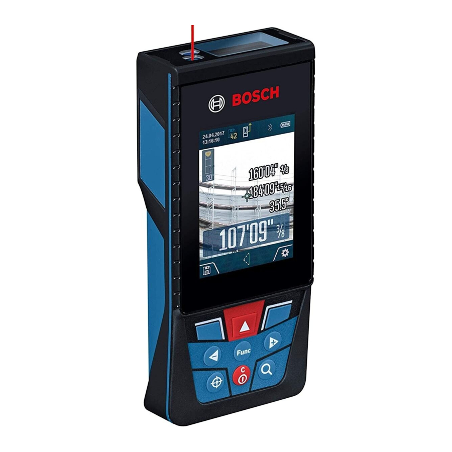
Features

- Display
- Measuring button
- Soft key
- Plus button (Select to the right)
- Zoom button
- Carrying strap lug
- Measuring pin release button
- Measuring pin
- On/Off/Clear button
- Digital Viewfinder button
- Minus button (Select to the left)
- Soft key
- Function button
- Laser warning label
- Serial number
- Battery lid
- 1/4" Tripod socket
- Reception lens
- Digital viewfinder
- Laser beam outlet
- Twist lock
- Batteries
- Protective pouch
- Carrying strap
- Laser target plate*
- Laser viewing glasses*
- Tripod*
Display Elements
- Result line
- Target indicator (crosshair)
- Display tilt angle
- Date/time
- Measurement reference level
- Connection status
![]() Bluetooth® not activated
Bluetooth® not activated
![]() Bluetooth® activated
Bluetooth® activated
![]() Bluetooth® Connected
Bluetooth® Connected - Battery indicator
- Measured-value lines
- Settings (soft key)
- Selected measuring function
- Internal memory (soft key)
- Help screen
- Back (soft key)
- Home screen (soft key)
- Tool settings
 Bluetooth® not activated
 Bluetooth® activated
 Bluetooth® Connected
Accessory

Technical Data
| Digital Laser Measure | GLM400C |
| Measuring range (typical) | 3 in - 400 ft (0.08 –122 mA) |
| Measuring range (typical, unfavorable conditions) | 196 ft (60 mB) |
| Measuring accuracy (typical) | ±1/16 in (±1.5 mmA) |
| Measuring accuracy (typical, unfavorable conditions) | ±1/10 in (±3 mmB) |
| Lowest indication unit | 1/32 in (0.5 mm) |
| Indirect Distance Measurement and Vial | |
| 0°–360° (4x90°) |
| Gradient measurement | |
| 0°–360° (4x90°) ±0.2° C)/D)/H) 0.1° |
| Operating temperature | +14°F to 113°F (-10°C to +45°C)E) |
| Storage temperature | -4°F to 158°F (-20°C to +70°C) |
| Relative air humidity, max. | 90 % |
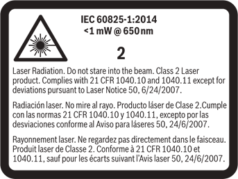
| Laser class | 2 |
| Laser type | 650 nm, <1mW |
| Laser beam diameter at 77°F (25°C) | |
| .35 in (9 mm) 3.5 in (90 mm) |
| Automatic switch-off after approx. | |
| 20 s AdjustableG |
| Weight | .46 lb (0.21 kg) |
| Dimensions | 5.5 (6.9) x 2.5 x 1.1 in (142 (176) x 64 x 28 mm) |
| Batteries | 3 x 1.5V (AA) |
| Degree of Protection | IP54 (dust and splash water protected)D) |
| Bluetooth® | Bluetooth® (4.1 low-energy)F) |
| Operating frequency band | 2402 – 2480 MHz |
| Max. transmission power | 8 mW |
- For measurements from the front edge of the measuring tool, applies to high reflectivity of the target (e.g. a white-painted wall), weak backlighting and 25°C operating temperature. In addition, a deviation of ±0,05mm/m must be taken into account.
- For measurements from the front edge of the measuring tool, applies to high reflectivity of the target (e.g. a white-painted wall), and strong backlighting. In addition, a deviation of ±0.15 mm/m must be taken into account.
- After calibration at 0° and 90° with an additional pitch error of max. ±0.01°/degrees up to 45°. The measurement accuracy is related to the 3 orientations based on the calibration of the inclination (tilt measurement), see picture H.
- At 25°C operating temperature.
- In the continuous measurement function, the maximum operating temperature is +40°C.
- When using Bluetooth® Low Energy tools, it may not be possible to establish a connection depending on the model and operating system. Bluetooth® devices must support the GATT profile.
- Automatic switch-off of the measuring tool is adjustable after 2, 5, 10 minutes or never.
- The left-hand side of the measuring tool serves as the reference level for grade measurement.
A long battery runtime is achieved by means of energy-saving measures, such as deactivating the Bluetooth® function when not required, or reducing the display brightness, etc.
The measuring tool can be clearly identified with the serial number 15 on the type plate.
Assembly
Inserting/Replacing the Batteries
AA alkaline batteries are recommended for the measuring tool.
To open the battery lid, press the latch in the direction of the arrow and remove the battery lid. Insert the batteries. When inserting, pay attention to the correct polarity according to the representation on the inside of the battery compartment.
When the battery symbol ![]() appears for the first time on the display, measurements are still possible for approx. 15 minutes. When the battery symbol flashes, the batteries must be replaced; measurements are no longer possible.
appears for the first time on the display, measurements are still possible for approx. 15 minutes. When the battery symbol flashes, the batteries must be replaced; measurements are no longer possible.

Always replace all batteries at the same time. Only use batteries from one brand and with the identical capacity.
Remove the batteries from the tool when not using it for extended periods. When storing for extended periods, the batteries can corrode and discharge themselves.
Operation
Protect the tool against moisture and direct sun irradiation.
Do not subject the tool to extreme temperatures or variations in temperature. As an example, do not leave it in vehicles for longer periods. In case of large variations in temperature, allow the tool to adjust to the ambient temperature before putting it into operation. In case of extreme temperatures or variations in temperature, the accuracy of the tool can be impaired.
Avoid heavy impact or falling of the tool. After heavy exterior impact on the tool, an accuracy check should always be carried out before continuing to work (see "Accuracy Check of the Distance Measurement").
DO NOT stare directly at the laser beam or project the laser beam directly into the eyes of others. Serious eye injury could result.
Do not leave the switched on measuring tool unattended and switch the tool off after use. Other persons could be blinded by the laser beam.
Switching On and Off
During work, ensure that the reception lens 20, laser beam output 18, and digital viewfinder 19 are not closed off or covered, otherwise correct measurement will not be possible.
- Tos witch on the measuring tool and the laser, briefly press the On/Off button 9 [
![]() ], front or side measuring button 2 [
], front or side measuring button 2 [![]() ].
].
Do not point the laser beam at persons or animals and do not look into the laser beam yourself, not even from a large distance. - To switch off the laser, press the On/Off button 9 [
![]() ].
]. - To switch off the digital viewfinder, press the digital viewfinder button 10.
- To switch off the measuring tool, press and hold the On/Off button 9 [
![]() ].
].
The measured values and device settings in the memory are retained when you switch the tool off.
Measuring Procedure
Once switched on, the measuring tool is in the continuous laser measurement function. For a different measuring function, press the button 13 [Func]. Select the desired measuring function with the buttons 4 [+] or the button 11 [–] (see "Measuring Functions". Activate the measuring function with button 13 [Func] or with the measuring button 2 [![]() ].
].
After switching on, the rear edge of the measuring tool is preset as the reference level for the measurement. To change the reference level, see "Selecting the Reference Level".
Place the measuring tool against the desired starting point of the measurement (e.g. a wall).
 Note: If the measuring tool has been switched on using the On/Off button 9 [
![]() ], briefly press the measuring button 2 [
], briefly press the measuring button 2 [![]() ] to switch the laser on.
] to switch the laser on.
To initiate the measurement, briefly press the measuring button 2 [![]() ]. Then the laser beam is switched off. For a further measurement, repeat this process.
]. Then the laser beam is switched off. For a further measurement, repeat this process.
With the laser beam continuously switched on and in the the continuous measurement function, measurement will begin after the measuring button 2 [![]() ] is pressed for the first time.
] is pressed for the first time.
Do not point the laser beam at persons or animals and do not look into the laser beam yourself, not even from a large distance.
Note: The measured value typically appears within 0.5 s and no later than approx. 4 s. The duration of the measurement depends on the distance, the lighting conditions and the reflective properties of the target surface. Upon completion of the measurement, the laser beam is automatically switched off. The continuously switched-on laser beam is not switched off after the measurement (see "Permanent Laser Beam").
Selecting the Reference Level
(see figure A)

You can choose between four different reference levels for the measurement:
- the rear measuring-tool edge (e.g. when measuring onward from a wall),
- the tip of the 180° folded-out measuring pin 8 (e.g. when measuring from a corner),
- the front measuring-tool edge (e.g. when measuring onward from a table edge),
- the center of thread 17 (e.g. for tripod measurements).
Folding out and in of the measuring pin 8 by 180° is detected automatically and the appropriate reference level is suggested. Confirm the setting by pressing the measuring button 2 [![]() ].
].
Use the soft key 3 [![]() ] to select the basic settings for the measuring tool. Use buttons 4 [+] or 11 [–] to select the reference level and confirm this by pressing button 13 [Func].
] to select the basic settings for the measuring tool. Use buttons 4 [+] or 11 [–] to select the reference level and confirm this by pressing button 13 [Func].
The rear edge of the measuring tool is automatically preset as the reference level every time the measuring tool is switched on.
Permanent Laser Beam
If necessary, you can switch the measuring tool to permanent laser beam operation. To do so, use soft key 3 [![]() ] to select the basic settings for the measuring tool. Use buttons 4 [+] or 11 [–] to select the permanent laser beam and confirm this by pressing button 13 [Func].
] to select the basic settings for the measuring tool. Use buttons 4 [+] or 11 [–] to select the permanent laser beam and confirm this by pressing button 13 [Func].
Do not point the laser beam at persons or animals and do not look into the laser beam yourself, not even from a large distance.
In this setting, the laser beam remains switched on even between measurements; measurement simply requires one brief press of the measuring button 2 [![]() ].
].
The permanent laser beam can be switched off again in the basic settings or automatically when the measuring tool is switched off.
"Settings" Menu
To enter the "settings" menu (i) briefly press soft key 3 [![]() ] or press and hold button 13 [Func].
] or press and hold button 13 [Func].
Use button 4 [+] or 11 [–] to select the relevant basic setting and press button 13 [Func] to select the required setting.
To exit the "settings" menu, press the On/Off button 9 [![]() ] or soft key 12 [
] or soft key 12 [![]() ].
].
 Settings Settings | |
 | Bluetooth® |
 | Reference Level |
 | Meas Timer |
 | Permanent Laser |
 | Tilt Calibration |
 | Viewfinder Calibration |
 | Memory |
 | Tool Settings |
Timer Function
The timer function is useful when measuring in hard-to-reach areas, for example, or when the measuring tool should be kept stationary during measurement.
Select the timer function in the settings. Select the required time period between triggering the timer and starting measurement and confirm by pressing the measuring button 2 [![]() ] or button 13 [Func].
] or button 13 [Func].
Next, press the measuring button 2 [![]() ] to switch on the laser beam and focus on the target. Press the measuring button 2 [
] to switch on the laser beam and focus on the target. Press the measuring button 2 [![]() ] once more to start the measurement. The measurement will begin after the set time period has expired. The measured value is displayed in the result line a.
] once more to start the measurement. The measurement will begin after the set time period has expired. The measured value is displayed in the result line a.
The time period between triggering the timer and starting measurement is displayed in the status bar at the top.
Continuous measurement and minimum/maximum measurement are not possible with the timer function enabled.
The timer remains enabled until the measuring tool is switched off or until the timer is switched off in the menu "settings".
Digital Viewfinder
To switch on the digital viewfinder 19, press the digital viewfinder button 10.
The digital viewfinder 19 is optimized for the detection of the laser point from a distance and therefore has a small visual field.
Optimizing Visibility of the Laser Beam
Especially when using the measuring tool outdoors, in sunlight and also over long distances indoors, it may be that the laser point is not visible. The visibility of the laser point/ measuring target can be improved additionally to switching on the camera by:
- Setting the display brightness (tool settings)
- Using the zoom by pressing button 5
"Tool Settings" Menu
Select the menu "Tool Settings" in the menu "Settings".
Use button 4 [+] or 11 [–] to select the desired tool setting and confirm with button 13 [Func]. Select the desired tool setting.
To exit the "Tool" menu (o), press the On/Off/Clear button 9 [![]() ] or soft key 12 [
] or soft key 12 [![]() ].
].
 Tool Settings Tool Settings | |
 | Language |
 | Time & Date |
| ft/m | Measurement Unit |
 | Angle Unit |
 | BlueHound |
 | Tool Information |
 | Audio Signals |
 | Shutdown Time |
 | Dimming |
 | Brightness |
 | Auto Rotate |
Setting the Language
Select the language in the basic settings (general settings).
Set the required language and confirm by pressing button 13 [Func] or button 2 (measuring).
Setting the Date and Time
Select the date and time in the basic settings (general settings).
Set the date and time and confirm by pressing soft key 12 [![]() ].
].
Changing the Unit of Measure
Select the "Measurement unit" in the tool settings.
Unit of measure "in" (inches) is set by default.
Set the required unit of measure and confirm by pressing button 13 [Func].
To exit the menu item, press the On/Off/Clear button 9 [![]() ] or soft key 3 [
] or soft key 3 [![]() ]. The selected setting remains saved after you switch off the measuring tool.
]. The selected setting remains saved after you switch off the measuring tool.
Changing the Angle Unit
Select the "Angle unit" in the tool settings.
Angle unit " " (grade) is set by default.
Set the required angle unit and confirm by pressing button 13 [Func].
To exit the menu item, press the On/Off/Clear button 9 [![]() ] or soft key 3 [
] or soft key 3 [![]() ]. The selected setting remains saved after you switch off the measuring tool.
]. The selected setting remains saved after you switch off the measuring tool.
BlueHound
Select "BlueHound" in the tool settings.
Confirm the setting by pressing button 13 [Func].
An initial activation is required. Data transmission is only possible with the corresponding app or the corresponding PC program.
After exchanging the batteries, the tool has to be switched on shortly to re-activate BlueHound. BlueHound can be disabled at any time.
Display Illumination
Select the display illumination in the basic settings (general settings).
The display illumination is continuously switched on. When no button is pressed, the display illumination is dimmed after approx. 30 seconds to preserve the batteries.
The time until start of dimming is adjustable (tool settings).
The brightness of the display can be adjusted to the surrounding conditions in multiple increments (general settings).
Measuring Functions
Note: Integrated Help Function
Help in the form of an animation is stored in the measuring tool for each measuring function. To do so, select button 13 [Func], buttons 4 [+] or 11 [–] and then soft key 3 [![]() ].
].
The animation shows you the detailed procedure for the selected measuring function. The animation can be stopped and started again at any time. You can scroll forward and back with buttons 4 [+] or 11 [–].
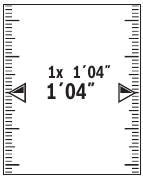
Length Measurement
Select the length measurement  .
.
To switch on the laser beam, briefly press the measuring button 2 [  ].
].
To measure, briefly press the measuring button 2 [![]() ].
].
The measured value will be shown at the bottom of the display.
Repeat the above-mentioned steps for each subsequent measurement. The last measured value is at the bottom of the display, the penultimate measured value is above it, and so on.
Continuous Measurement (Tracking)
For continuous measurements, the measuring tool can be moved relative to the target, whereby the measuring value is updated approx. every 0.5 seconds. In this manner, as an example, you can move a certain distance away from a wall, while the actual distance can always be read.
Select the continuous measurement ![]() .
.
To switch on the laser beam, briefly press the measuring button 2 [![]() ].
].
Move the measuring tool until the required distance value is indicated in the bottom of the display.
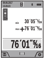
Briefly pressing the measuring button 2 [![]() ] interrupts the continuous measurement. The current measured value will be shown at the bottom of the display. The maximum and minimum measured value appear above it. Pressing the measuring button 2 [
] interrupts the continuous measurement. The current measured value will be shown at the bottom of the display. The maximum and minimum measured value appear above it. Pressing the measuring button 2 [![]() ] once more restarts the continuous measurement.
] once more restarts the continuous measurement.
Continuous measurement automatically switches off after 5 mins.
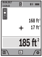
Area Measurement
Select the area measurement ![]() .
.
Then measure the width and length one after the other as with a length measurement. The laser beam remains switched on between the two measurements. The distance to be measured flashes in the indicator for area measurement ![]() .
.
The first measured value is shown at the top of the display.
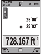
After the second measurement has been completed, the area will be automatically calculated and displayed. The end result is shown at the bottom of the display, while the individual measured values are hown above it.
Volume Measurement
Select the volume measurement ![]() .
.
Then measure the width, length and depth one after the other as with a length measurement. The laser beam remains switched on between the three measurements. The distance to be measured flashes in the indicator for volume measurement ![]() .
.
The first measured value is shown at the top of the display.
After the third measurement has been completed, the volume will be automatically calculated and displayed. The end result is shown at the bottom of the display, while the individual measured values are shown above it.
Indirect Distance Measurement
Select the indirect distance measurement  .
.
There are four measuring functions available for the indirect distance measurement, each of which is capable of determining different distances.
The indirect distance measurement is used to measure distances that cannot be measured directly because an obstacle would obstruct the laser beam or no target surface is available as a reflector. This measuring procedure can only be used in vertical direction. Any deviation in horizontal direction leads to measuring errors.
Note: Indirect distance measurement is always less accurate than direct distance measurement. Depending on application, greater measuring errors are possible than with direct distance measurement. To improve the measuring accuracy, we recommend using a tripod (accessory).
The laser beam remains switched on between the individual measurements.
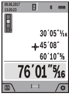
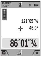
- Indirect height measurement (see figure B)

Fig. B
Select the indirect height measurement![]() .
.
Ensure that the measuring tool is at the same height as the lower measuring point. Then tilt the measuring tool around the reference level and measure the distance "1" as for a length measurement (displayed as a red line).
Upon completion of the measurement, the result for the sought distance "X" is displayed in the result line a. The measuring values for the distance "1" and the angle "![]() " are displayed in the measured-value lines h.
" are displayed in the measured-value lines h.
![]()
- Double indirect height measurement (see figure C)

Fig. C
The measuring tool can indirectly measure all distances, which lie in the vertical level of the measuring tool.
Select the double indirect height measurement![]() .
.
Measure distances "1" and "2" in this sequence as for a length measurement.
Upon completion of the measurement, the result for the sought distance "X" is displayed in the result line a. The measuring values for the distances "1", "2" and the angle "![]() " are displayed in the measured-value lines h.
" are displayed in the measured-value lines h.
![]()
Pay attention that the reference plane of the measurement (e.g. the rear edge of the measuring tool) remains exactly at the same location for all individual measurements within a measuring sequence. - Indirect length measurement (see figure D)

Fig. D
Select the indirect length measurement![]() .
.
Pay attention that the measuring tool is positioned at the same height as the sought measuring point. Now, tilt the measuring tool around the reference plane and measure distance "1" as for a length measurement.
Upon completion of the measurement, the result for the sought distance "X" is displayed in the result line a. The measuring values for the distance "1" and the angle "![]() " are displayed in the measured-value lines h.
" are displayed in the measured-value lines h.
![]()
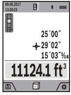
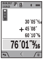
- Trapezium measurement (see figure E)

Fig. E
The trapezium measurement can be used to determine the length of a roof slope, for example.
Select the trapezium measurement![]() .
.
Measure distances "1", "2" and "3" in this sequence with a length measurement. Pay attention that the measurement of distance "3" starts exactly at the end point of distance "1" and that a right angle exists between distances "1" and "2" as well as between "1" and "3".
Upon completion of the last measurement, the result for the sought distance "E" is displayed in the result line a. The individual measured values are displayed in the measured-value lines h.
![]()

 .
.

 " are displayed in the measured-value lines h.

 .
.

 .
.
Wall Area Measurement
(see figure F)

Fig. F
The wall area measurement is used to determine the sum of several individual surfaces with a common height.
In the illustrated example, the total area of several walls should be determined, which have the same ceiling height H, but different lengths L.
Select the wall area measurement ![]() .
.
Measure the ceiling height H as with a length measurement.
The measured value is displayed in the top measured-value line. The laser remains switched on.
Then measure the length L1 of the first wall. The surface is automatically calculated and displayed in the result line a. The last length measured value is in the bottom measured-value line h. The laser 103´00˝ remains switched on.
Now measure the length L2 of the second wall. The individual measured value displayed in the measured-value line h is added to the length L1. The sum of the two lengths (displayed in the bottom measured-value line h) is multiplied by the saved height H. The total surface value is displayed in the result line a.
You can measure any number of lengths LX, which will be automatically added and multiplied by the height H.
The requirement for a correct area calculation is that the first measured length (for example the ceiling height H) is identical for all sub-areas.
Stake out function
(see figure G)

Fig. G
The stake out function repeatedly measures a defined length (distance). These lengths can be transferred to a surface, for example to enable material to be cut into pieces of equal lengths or to install stud walls in a drywall construction. The minimum adjustable length is 3.2 ft (0,1m), the maximum adjustable length is 164 ft (50m).
Select the stake out function ![]() .
.
Set the desired length. Using button 13 [Func] select the corresponding digit/position and change the value with button 4 [+] or button 11 [–].
Begin the stake out function by pressing the measuring button 2 [ ] and slowly move away from the starting point.
The measuring tool continuously measures the distance to the starting point. The defined length and the current measured value are thereby displayed. The lower or upper arrow displays the 1 shortest distance to the next or last marking.
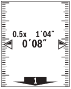
Note: The continuous measuring enables you to set a measured value as a defined length by pressing the button 3.
The left factor specifies how many times the defined length has already been reached. The green arrows on either side of the display indicate the reaching of a length for marking purposes.
Red arrows or a red label indicate the actual value if the reference value is outside the display.
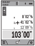
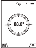
Gradient Measurement/Digital Spirit Level
Select the inclination measurement/digital spirit level ![]() .
.
The measuring tool automatically switches between two states.
The digital spirit level is used to check the horizontal or vertical alignment of an object (e.g. washing machine, refrigerator, etc.). When the inclination 3° exceeds, the ball in the display lights red.
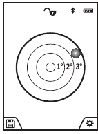
Gradient measurement is used to measure a slope or incline (e.g. of stairs, railings, when fitting furniture, laying pipes, etc.). The left-hand side of the measuring tool serves as the reference level for grade measurement. If the display flashes during measurement, the measuring tool has been tipped too heavily to the side.
Memory Functions
The value or end result of each completed measurement is automatically saved.
Memory value display
A maximum of 50 values can be retrieved.
Select the memory function using soft key 12 [![]() ].
].
The number of the memory value is shown at the top of the display, the corresponding memory value is shown at the bottom and the corresponding measuring function is shown below.
Press button 4 [+] to browse forwards through the saved values.
Press button 11 [–] to browse backwards through the saved values.
If there is no value available in the memory, "0.000" is shown at the bottom of the display and "0" at the top.
The oldest value is located in position 1 in the memory, while the newest value is in position 50 (when 50 memory values are available). When a further value is saved, the oldest value in the memory is always deleted.
Deleting the Memory
To delete the content of the memory, press soft key 12 [ ] and then, as many times as required, press soft key 3 [
 ].
].
To delete all values stored in the memory, the function can be used. Confirm by pressing soft key 12 [![]() ].
].
Adding/Subtracting Values
Measured values or end results can be added or subtracted.
Adding Values
The following example describes the addition of areas: Measure an area as described in section "Area Measurement".
Press the button 4 [+]. The calculated area and the symbol "+" will be displayed.
Press the measuring button 2 [![]() ] to start another area measurement. Measure the area as described in section "Area Measurement". Once the second measurement is completed, the result of the second area measurement is displayed below. To show the end result, press the measurement button 2 [
] to start another area measurement. Measure the area as described in section "Area Measurement". Once the second measurement is completed, the result of the second area measurement is displayed below. To show the end result, press the measurement button 2 [![]() ] once more.
] once more.
Note: With a length measurement, the end result is displayed immediately.
Subtracting Values
To subtract values, press button 11 [–]. The subsequent steps are the same as for "Adding Values".
Deleting Measured Values
Briefly pressing the On/Off/Clear button 9 [![]() ] will delete the last measured value in all measuring functions.
] will delete the last measured value in all measuring functions.
Bluetooth® Interface
Do not turn on laser remotely using the Bosch app without line of sight to the laser tool. The sudden bright laser beam may increase the risk of personal injury or property damage.
Ensure there are no bystanders in the direct path of the laser beam before turning on the laser remotely.
Data Transmission to other Devices
The measuring tool is equipped with a Bluetooth® module, which enables data transmission via radio technology to certain mobile terminals/devices with a Bluetooth® interface (e.g., smartphones, tablets).
For information on the necessary system requirements for a Bluetooth® connection, please refer to the Bosch website at www.bosch-pt.com
Further information can be found on the Bosch product page
For data transmission via Bluetooth®, time delays between mobile terminal/device and measuring tool may occur. This can be possible due to the distance between both devices or the object being measured.
Activating the Bluetooth® Interface for Data Transmission to a Mobile Terminal/Device
The Bluetooth® interface is activated in the basic settings. To activate the Bluetooth® signal, press button 4 [+]. Ensure that the Bluetooth® interface is activated on your mobile end device.
The special Bosch "Measuring Master" app is available to extend the range of functions of the mobile end device and to make data easier to process. You can download this from the store for your end device type.
The connection between mobile terminal/device and measuring tool is established after the Bosch application has started. If multiple active measuring tools are found, select the appropriate measuring tool using the serial number.
The connection status, as well as the active connection (f), are shown in the display 1 of the measuring tool.
Deactivating the Bluetooth® Interface
The Bluetooth® connection is deactivated in the basic settings. To deactivate the Bluetooth® signal, press button 11 [–] or switch off the measuring tool.
Working Advice
Further information can be found on the Bosch product page.
The measuring tool is equipped with a radio interface. Local operating restrictions, e.g. in airplanes or hospitals, are to be observed.
General Information
The reception lens 18, the laser beam output 20 and the digital viewfinder 19 must not be covered during measurement.
The measuring tool must not be moved while taking a measurement. Therefore, place the measuring tool, as far as this is possible, against or on a firm stop or supporting surface.
Influence Effects on the Measuring Range
The measuring range depends on the lighting conditions and the reflective properties of the target surface. For better visibility of the laser beam in strong extraneous light, use the integrated digital viewfinder 19, the laser viewing glasses 26 (accessory) and the laser target plate 25 (accessory) or shade the target area.
Influence Effects on the Measuring Result
Due to physical effects, faulty measurements cannot be excluded when measuring on different surfaces. Included here are:
- Transparent surfaces (e.g., glass, water),
- Reflecting surfaces (e.g., polished metal, glass),
- Porous surfaces (e.g. insulation materials),
- Structured surfaces (e.g., roughcast, natural stone).
If required, use the laser target plate 25 (accessory) on these surfaces.
Furthermore, faulty measurements are also possible when sighting inclined target surfaces.
Also, air layers with varying temperatures or indirectly received reflections can affect the measured value.
Accuracy Check and Calibration of the Grade Measurement
(see figure H)

Fig. H
Regularly check the accuracy of the grade measurement. This is done by carrying out a reversal measurement. For this, place the measuring tool on a table and measure the grade.
Turn the measuring tool by 180° and measure the grade again. The difference of the indicated reading may not exceed by more than 0.3° (max.).
In the event of larger deviations, you have to recalibrate the measuring tool. For this, select . Follow the instructions on the display.
After severe temperature changes and impact, we recommend an accuracy check and, if required, to recalibrate the measuring tool. After a temperature change, the measuring tool must acclimate for a while before calibrating.
Accuracy Check of the Distance Measurement
The accuracy of the measuring tool can be checked as follows:
- Select a permanently unchangeable measuring section which is approx. 9.8 to 32 ft (3 to 10 m) long and which you know the exact length of (e.g. room width, door opening). The measurement should be performed under favorable conditions, i.e. the measuring section should be indoors with weak backlighting and the target area of the measurement should be smooth and reflect well (e.g. a white-painted wall).
- Measure the distance 10 times in succession.
The deviation of the individual measurements from the average value must not exceed ±.07 in (±2 mm) over the entire measuring section in favorable conditions. Record the measurements in order to be able to compare the accuracy at a later date.
Checking Accuracy and Calibrating the Target Indicator (Crosshair)
Check the accuracy of the alignment of the laser and target indicator on a regular basis.
- Select a bright area at least 10 m away with as little illumination as possible as the target.
- Check whether the laser point is inside the target indicator in the display.
If the laser point is not inside the target indicator, you must recalibrate the target indicator. To do so, select ![]() in the settings. Follow the instructions on the display.
in the settings. Follow the instructions on the display.
Working with the Tripod (Accessory)
The use of a tripod is particularly necessary for larger distances.
Position the measuring tool with the 1/4" thread 17 onto the quick-change plate of the tripod 27 or a commercially available camera tripod. Tighten the measuring tool with the locking screw of the quick-change plate.
Set the reference level for measurements with a tripod in the basic settings (thread reference level).
Troubleshooting
| Cause | Corrective Measure |
| Temperature warning flashes, measurement not possible | |
| Measuring tool not within the temperature range between +14°F and 113°F ( –10°C and +45°C). | Wait until the measuring tool has reached the operating temperature. |
| "ERROR" indication in the display | |
| Addition/Subtraction of measured values with different units of measure. | Only add/subtract measured values with the same units of measure. |
| The angle between the laser beam and the target is too acute. | Enlarge the angle between the laser beam and the target. |
| The target surface reflects too intensely (e.g. a mirror) or insufficiently (e.g. black fabric), or the ambient light is too bright. | Work with the laser target plate 25 (accessory). |
| The laser beam outlet 20, reception lens 18, and/or digital viewfinder 19 are misted up (e.g. due to a rapid temperature change). | Wipe the laser beam outlet 20, the reception lens 18, and/or digital viewfinder 19 dry using a soft cloth. |
| Calculated value is greater than 1 999 999 or smaller than –999 999in/in2/in3. | Divide calculation into intermediate steps. |
| "CAL" and "ERROR" indication in the display | |
| The calibration of the grade measurement was not carried out in the correct sequence or in the correct positions. | Repeat the calibration according to the instructions on the display and in the operating instructions. |
| The surfaces used for the calibration were not accurately aligned (horizontal or vertical). | Repeat the calibration on a horizontal or vertical surface; if required, check the surface first with a level. |
| The measuring tool was moved or tilted while pressing the button. | Repeat the calibration and hold the measuring tool in place while pressing the button. |
| Bluetooth® cannot be activated | |
| The battery is too low. | Change the measuring tool's battery. |
| No Bluetooth® connection | |
| Failure of the Bluetooth® connection | Switch off and restart Bluetooth® on the measuring tool and the mobile device. Check the application on your mobile terminal/device. Check if Bluetooth® is activated on your measuring tool and mobile terminal/ device. Check your mobile terminal/ device for overload. Reduce the distance between measuring tool and your mobile terminal/device. Avoid obstructions (e.g., reinforced concrete, metal doors) between measuring tool and your mobile terminal/device. Observe clearance to electromagnetic disturbances (e.g., WLAN transmitters). |
| Measuring result not plausible | |
| The target surface does not reflect correctly (e.g. water, glass). | Cover off the target surface. |
| Laser beam output 20, reception lens 18 or digital viewfinder 19 is covered. | Keep the laser beam output 20, reception lens 18 and digital viewfinder 19 clear. |
| Wrong reference level set. | Select reference level that corresponds to measurement. |
| Obstruction in path of laser beam. | Laser point must be completely on target surface. |
The measuring tool monitors the correct function for each measurement. When a defect is determined, only the symbol shown aside flashes in the display. In this case, or when the above mentioned corrective measures cannot correct an error, have the measuring tool checked by an after-sales service agent for Bosch power tools.
Maintenance and Service
Keep the measuring tool clean at all times.
- Do not immerse the measuring tool into water or other fluids.
- Wipe off debris using a moist and soft cloth. Do not use any cleaning agents or solvents.
- Take extra special care when cleaning the reception lens 18, the laser beam exit opening 20 and the viewfinder 19:
- Ensure that there is no lint on the reception lens, the laser beam exit opening and the digital viewfinder. Clean the reception lens, the laser beam exit opening and the viewfinder only with cleaning agents which are also suitable for camera lenses. Do not attempt to remove dirt from the reception lens, the laser beam exit opening and the viewfinder using pointed objects, and do not wipe over the reception lens, the laser beam exit opening and the viewfinder (risk of scratching).
- If the measuring tool should fail despite the care taken in manufacturing and testing procedures, repair should be carried out by an authorized after-sales service center for Bosch power tools. Do not open the measuring tool yourself.
- In all correspondence and spare parts orders, please always include the 10-digit article number given on the type plate of the measuring tool.
Safety Symbols
The definitions below describe the level of severity for each signal word. Please read the manual and pay attention to these symbols.
| | This is the safety alert symbol. It is used to alert you to potential personal injury hazards. Obey all safety messages that follow this symbol to avoid possible injury or death. |
 | Read manual symbol - Alerts user to read manual. |
| | WARNING indicates a hazardous situation which, if not avoided, could result in death or serious injury. |
General Safety Rules
Read all instructions. Failure to follow all instructions listed below may result in hazardous radiation exposure, electric shock, fire and/or serious injury. The term "tool" in the warnings listed below refers to your mains-operated (corded) tool or battery-operated (cordless) tool.
SAVE ALL WARNINGS AND INSTRUCTIONS FOR FUTURE REFERENCE
Work area safety
- Keep work area clean and well lit. Cluttered or dark areas invite accidents.
- DO NOT operate the laser tool around children or allow children to operate the laser tool. Serious eye injury could result.
- DO NOT use measuring tools, attachments and accessories outdoors when lightening conditions are present. E
lectrical safety
Batteries can explode or leak, cause injury or fire. To reduce this risk, always follow all instructions and warnings on the battery label and package.
- Do not short any battery terminals.
- Do not charge alkaline batteries.
- Do not mix old and new batteries. Replace all of them at the same time with new batteries of the same brand and type.
- Do not mix battery chemistries.
- Dispose of or recycle batteries per local code.
- Do not dispose of batteries in fire.
- Keep batteries out of reach of children.
- Remove batteries if the device will not be used for several months.
Personal safety
- Stay alert, watch what you are doing and use common sense when operating a measuring, detection and layout tool. Do not use a measuring, detection and layout tool while you are tired or under the influence of drugs, alcohol or medication. A moment of inattention while operating measuring, detection and layout tools may result in serious personal injury or incorrect measurement results.
- Use safety equipment. Always wear eye protection. Safety equipment such as dust mask, non-skid safety shoes, hard hat, or hearing protection used for appropriate conditions will reduce personal injuries.
- DO NOT use any optical tools such as, but not limited to, telescopes or transits to view the laser beam. Serious eye injury could result.
- DO NOT stare directly at the laser beam or project the laser beam directly into the eyes of others. Serious eye injury could result.
- Use caution when using measuring tools in the vicinity of electrical hazards.
Measuring, detection and layout tool use and care
- Use the correct measuring, detection and layout tool for your application. The correct measuring, detection and layout tool will do the job better and safer at the rate for which it was designed.
- Do not use the measuring, detection and layout tool if the switch does not turn it on and off. Any measuring, detection and layout tool that cannot be controlled with the switch is dangerous and must be repaired.
- Store idle measuring, detection and layout tools out of the reach of children and do not allow persons unfamiliar with the measuring, detection and layout tool or these instructions to operate the measuring, detection and layout tool. Measuring, detection and layout tools may be dangerous in the hands of untrained users.
- Maintain measuring, detection and layout tools. Check for misalignment or binding of moving parts, breakage of parts and any other condition that may affect the measuring, detection and layout tools operation. If damaged, have the measuring, detection and layout tool repaired before use. Many accidents are caused by poorly maintained measuring, detection and layout tools.
- Use the measuring, detection and layout tool, accessories, etc., in accordance with these instructions and in the manner intended for the particular type of measuring, detection and layout tool, taking into account the working conditions and the work to be performed. Use of the measuring, detection and layout tool for operations different from those intended could result in a hazardous situation.
Service
- Have your measuring, detection and layout tool serviced by a qualified repair person using only approved replacement parts. This will ensure that the safety of the measuring, detection and layout tool is maintained.
- Develop a periodic maintenance schedule for your measuring, detection and layout tool. Follow checking and recalibration procedures outlined in the instruction manual.
- When cleaning a tool be careful not to disassemble any portion of the tool since internal wires may be misplaced or pinched or may be improperly mounted. Certain cleaning agents such as gasoline, carbon tetrachloride, ammonia, etc. may damage plastic parts.
Safety Rules for Laser Tools
The following label is on your laser tool for your safety. ALWAYS BE AWARE of its location when using the tool.
![]()
DO NOT direct the laser beam at persons or animals and do not stare into the laser beam yourself. This tool produces class 2 laser radiation and complies with 21 CFR 1040.10 and 1040.11 except for deviations pursuant to Laser Notice No. 50, dated June 24, 2007. This can lead to persons being blinded.- DO NOT place the measuring tool in a position that may cause anyone to stare into the laser beam intentionally or unintentionally. Serious eye injury could result.
- Never aim the beam at a workpiece with a reflective surface. Bright shiny reflective sheet steel or similar reflective surfaces are not recommended for laser use. Reflective surfaces could direct the beam back towards the operator.
- DO NOT operate the measuring tool around children or allow children to operate the measuring tool. Serious eye injury could result.
- ALWAYS: Make sure that any bystanders in the vicinity of use are made aware of the dangers of looking directly into the measuring tool.
- Do not use the measuring tool to photograph any people or animals, as this involves the laser beam being continuously switched on. You could blind somebody or cause accidents or eye damage with the laser beam switched on.
- DO NOT remove or deface any warning or caution labels. Removing labels increases the risk of exposure to laser radiation.
- Do not use the measuring tool if the display glass is visibly damaged (e.g. cracks in the surface, etc.). This poses a risk of injury.
- DO NOT operate the measuring tool in combustible areas such as in the presence of flammable liquids, gases or dust.
- Use of controls or adjustments or performance of procedures other than those specified herein may result in hazardous radiation exposure.
- Do not use the laser viewing glasses as sun glasses or in traffic. The laser viewing glasses do not afford complete UV protection and reduce color perception.
- DO NOT leave measuring tool "ON" unattended in any operation mode.
- ALWAYS turn the measuring tool "OFF" when not in use. Leaving the measuring tool "ON" increases the risk of someone inadvertently staring into the laser beam.
- ALWAYS position the measuring tool securely. Damage to the measuring tool and/or serious injury to the user could result if the measuring tool falls.
- Take care to recognize the accuracy and range of the device. Measurement may not be accurate if used beyond the rated range of the device.
- ALWAYS use only the accessories that are recommended by the manufacturer of your measuring tool. Use of accessories that have been designed for use with other measuring tools could result in serious injury.
- DO NOT use this measuring tool for any purpose other than those outlined in this manual. This could result in serious injury.
- ALWAYS remove the batteries when cleaning the laser light aperture and laser lens.
- DO NOT disassemble the measuring tool. There are no user serviceable parts inside. Disassembling the laser will void all warranties on the product. Do not modify the product in any way. Modifying the measuring tool may result in hazardous laser radiation exposure.
- Repair and servicing must always be performed by a qualified repair facility. Repairs performed by unqualified personnel could result in serious injury.

1-877-BOSCH99 (1-877-267-2499)
Documents / Resources
References

Download manual
Here you can download full pdf version of manual, it may contain additional safety instructions, warranty information, FCC rules, etc.
Advertisement


Need help?
Do you have a question about the GLM400C and is the answer not in the manual?
Questions and answers