Advertisement
MAIN ROUTING OPTION
Configuration Mechanical

Configuration SHIMANO Di2

Configuration SRAM Etap

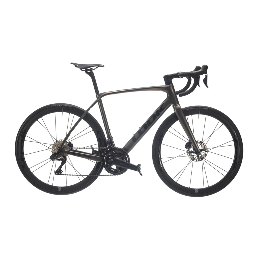
PRODUCT INTRODUCTION
Your 765 Optimum has been developed and designed to LOOK specifications to offer the best possible power transfer thanks to an enduranceoriented frame geometry and optimized comfort.
This is in part due to the integration of components specifically-designed for the frame. The result is a more coherent overall system, improved performance and full integration of all cables and hoses.
The 765 Optimum features a number of innovative features, including a new headset with special, newly-sized bearings for seamless internal routing through the spacers, an under-stem cable guide and a new stem design to create a single, harmonious unit.
Here are the key components of your new 765 Optimum:
- Integrated headset, 1"1/8 top and bottom.
- X12 thru axles. Front: 100mm M12 P1,5 total length 115mm. Rear: 142mm M12 P1,5, total length 160mm
- T47 bottom bracket, 85,5mm wide
- Chainstay thickness for disc brake caliper mount: 25mm
- Seatpost diameter: 27,2mm
- Max. tire width: 34mm
CABLE ROUTING
NOTE: Your 765 Optimum frame is originally designed for mechanical groupsets, but is also compatible with the majority of electronic groupsets on the market (Shimano DI2, SRAM AXS and CAMPAGNOLO mechanical & wireless).
Rear derailleur hanger: When installing the rear hanger, tighten the screws to a torque of 3Nm. If disassembling/reassembling, apply a drop of medium threadlocker (such as LOCTITE 243™) to each screw.
PRE-ASSEMBLY CHECK
Your frame is delivered with:
- Fork and headset
- Dedicated seatpost clamp.
- Thru axles.
- A pouch including the necessary parts to adapt the bike for electronic, mechanical or wireless shifting.
ROUTING YOUR 765 OPTIMUM
Open the pages containing figures 1-2 at the beginning of the manual and 3-4-5-6 at the end of the ROUTING section.
MECHANICAL CABLE ROUTING
(installation video available)

- You will need a workshop stand to assemble the bike. It is important to secure the frame by the seatpost, tightening to a torque of 7Nm. The frame must be stripped to allow easy access to the headset and bottom bracket, allowing you to route the housings through the down tube, the cable guide (20, fig. 1) to the front and rear derailleurs, and then the rear disc brake hose. Use 510mm-long foam tubes on the housings and on the rear brake hose to eliminate any unwelcome noise in the downtube.
- Start with the rear derailleur housing, which will run through the frame from the right rear dropout to the bottom bracket guide, up the down tube and to the handlebars by passing through the head tube and around the steerer tube, then through all the headset parts (7-12, Fig.1) and the upper bearing, which is specially designed for this purpose.

- Likewise, the front derailleur housing should be run from the bottom bracket guide (small curved bracket facing up) through the down tube and then the head tube, passing through the upper headset bearing and then through the same headset parts to the handlebars.
![]()
- Before installing the fork and headset, remember to slide the 510mm foam tubes over the two derailleur cable housings.
- Insert the rear brake hose through the left-hand chainstay, run it through the bottom bracket (above the aluminum insert) and up the down tube, then follow the same route through the headset to the handlebars.
- Sufficient length must be allowed for the more complex routing now concealed within the headset parts and through the housing guide (7, Fig. 1), which precisely routes the cable housings towards the handlebars and finally to the shifters. All these curves require a great deal of length, so it is always preferable to cut the housings once you have testrouted everything, leaving a 20cm margin before final assembly.
- Once the two derailleur cable housings and the rear brake hose are routed, it is time for the front brake. Slide it through the dedicated slot in the fork, leaving sufficient length to accommodate the bends under the stem and along the handlebars.
- Now place the fork in the frame, making sure the greased lower bearing is correctly seated on the fork cone. This brings us to the key step, where the 4 lines (cable housings + brake hoses) are located inside the head tube. Align all the headset parts, with the 2 oblong slots facing the front of the fork, and the 2 housings & 2 hoses should fit perfectly. To make this easier, we recommend that you use a bike stand that holds the fork as well as the frame. You will then have both hands free to guide the 4 lines through the riser, the spacers and then the cable guide (tutorial video available). Quickly place the stem over the top to add support and tighten slightly if necessary to prevent the stiffness of the hoses from pushing everything upward along the steerer tube.
- You can also use this pre-assembly to define the number of spacers required, how much to cut from the steerer tube and to help define the housing and hose length required before final assembly.
- If you need to cut the steerer tube, we highly recommend you remove the fork to do so. Note that this will of course affect the length of the housings and hoses.
- Finalize your setup and tighten to the recommended torques.


ELECTRONIC CABLE ROUTING

- You will need a workshop stand to assemble the bike. It is important to secure the frame by the seatpost, tightening to a torque of 7Nm. The frame must be stripped to allow easy access to the headset and bottom bracket, allowing you to route the brake hoses and e-tubes according to SHIMANO's instructions, from the battery in the seat tube to the front and rear derailleurs. Use 510mmlong foam tube on the rear brake hose to eliminate any unwelcome noise in the downtube.
- Route your electronic groupset according to SHIMANO's instructions.
- Place the battery in the seatpost according to SHIMANO's instructions, using the dedicated adapter.
![]()
- Insert the rear brake hose through the left-hand chainstay, run it over the bottom bracket and up the down tube, then follow the same route through the headset to the handlebars
![]()
- Insert the front brake hose into the opening on the left fork leg, then pull the hose up through the headset and out through the stem.
- Finalize the setup.


WIRELESS ELECTRONIC CABLE ROUTING

- You will need a workshop stand to assemble the bike. It is important to secure the frame by the seatpost, tightening to a torque of 7Nm. The frame must be stripped to allow easy access to the headset and bottom bracket, allowing you to route the rear brake hose. Use 510mm-long foam tube on the rear brake hose to eliminate any unwelcome noise in the downtube.

- As with the other builds, we recommend that you insert the rear brake hose through the left-hand chainstay, run it over the bottom bracket and up the down tube, then follow the same route through the headset (upper bearing and spacers) to the handlebars.
- Similarly, the front brake hose must slot through the opening in the steerer tube and exit at the fork leg. If the brake caliper is already mounted, feed the hose through the fork leg first and out through the opening in the steerer tube.
![]()
- Mount the groupset according to the manufacturer's instructions.
- Place grommets in all the mechanical cable openings.
- Finalize the setup.


TIGHTENING TORQUES
(Do NOT exceed the maximum torque as this may damage your frame)
| NO. | Name | Spec. | Torque | Supplier | assembling | Qty | Unit |
| 1 | Screw | M6*P1.0*L30mm | 2Nm | Token | Ming | 1 | pcs |
| 2 | stem cap | Token | Ming | 1 | pcs | ||
| 3 | expander | 8Nm | Token | Ming | 1 | set | |
| 4 | Screw | M5*P0.8*L17mm | 5Nm | Token | Ming | 6 | pcs |
| 5 | Stem | Token | Ming | 1 | pcs | ||
| 6 | Stem Cap | Token | Ming | 1 | 1 | ||
| 7 | Stem cable guide | Token | Ming | 1 | pcs | ||
| 8 | Head spacer | 5mm/half | Token | Ming | 4 | pcs | |
| 9 | Head spacer | 10mm/half | Token | Ming | 8 | pcs | |
| 10 | Head cap | Token | Ming | 1 | pcs | ||
| 11 | Seal | Token | Ming | 1 | pcs | ||
| 12 | compress ring | Token | Ming | 1 | pcs | ||
| 13 | Bearing | Φ49.5*Φ40*6.5mm | Token | Ming | 2 | pcs | |
| 14 | Front thru axle | M12*P1.5*L115mm | 11Nm | Tranz X | Ming | 1 | pcs |
| 15 | Screw | M5*P0.8*16mm | 4Nm | ADV | Ming | 6 | pcs |
| 16 | Screw | M5*P0.8*20MM | 7Nm | ADV | Ming | 1 | pcs |
| 17 | washer | Φ9.0*5.3*T1mm | ADV | Ming | 1 | pcs | |
| 18 | Wedge Top part | ADV | Ming | 1 | pcs | ||
| 19 | Wedge low part | ADV | Ming | 1 | pcs | ||
| 20 | BB cable guied | for mechanical | ADV | Ming | 1 | pcs | |
| 21 | BB cable cover | for Di2 | ADV | Ming | 1 | pcs | |
| 22 | Seatpost | Φ27.2 | LOOK | Ming | 1 | pcs | |
| 23 | Rear thru Axle | M12*P1.5*L160mm | 11Nm | Tranz X | Ming | 1 | pcs |
| 24 | Hanger-2 | inside | ADV | Ming | 1 | pcs | |
| 25 | rubber cable guide | for rear brake(Φ5.2) | ADV | Ming | 1 | pcs | |
| 26 | rubber cable guide | for mechanical(Φ4.3) | ADV | Ming | 1 | pcs | |
| 27 | rubber cable guide | for Di2(Φ2.8) | ADV | Ming | 1 | pcs | |
| 28 | Hanger-1 | outside | ADV | Ming | 1 | pcs | |
| 29 | Screw | M4*P0.7*14mm | 3Nm | ADV | Ming | 3 | pcs |
| 30 | SS Bridge | by size | ADV | Ming | 1 | pcs | |
| 31 | rubber plug | cover for Φ7.5 on ST | ADV | Ming | 1 | pcs |
OVERVIEW

SEATPOST ASSEMBLY
The frame is supplied with a special internal seatpost clamp to secure the seatpost in the frame. This clamp is tightened to a torque of 7Nm. Take care not to exceed this torque, as this may not only damage your seatpost but also cause cracks around the insertion point in the frame.


MUDGUARDS
1/ASSEMBLY
The 765 frame is designed for standard 4mm fender stays, with small grub screws to secure them in place. A dedicated Stronglight model with double brackets attaches to the M4 lateral threads instead of the pre-assembled M4 grub screws.
To secure the fender, two M5 inserts are located behind the seat tube and behind the bottom bracket, between the two chainstays. Finally, the use of a bridge is necessary, particularly if you do not wish to use the dedicated model.
If your standard mudguard only has one rear bracket, the bridge must be added to reinforce the setup. Note that this will stiffen the 2 seatstays and limit their vibration-filtering function.
Similarly, the fork has 4mm slots on the rear of the dropouts, and an M5 insert under the crown for standard fender assembly.

ASSEMBLY INSTRUCTIONS
FRONT FENDER
Secure the front fender to the fork using the 5mm Ø12 spacer, M5x20 CHC screw and washer. Tighten the screw to 6 Nm.

Fit the stays to the fender using the base lock nut on the outside and the TBHC M4x8 screw and washer on the inside of the fender.
Tighten the nuts to a torque of 4 Nm.

Insert the stays into the bottom of the fork to complete the front fender assembly.
Secure the stays using the M4x8 screw and tighten to a torque of 4 Nm.

REAR FENDER
Just like on the front fender, secure the stays to the fender using the TBHC M4x8 screw and washer on the inside and the base lock nut on the outside.
Repeat the operation four times for all the rear fender stays.
In the case of standard assembly (classic fender without double stays), you may also use the bridge supplied with the frame.
Secure the fender to the frame using the bridge.
Secure the bracket to the seatstay using the CHC M4x10 screw.
Mark the position of the two bridge mount holes on the fender.
Using a drill, bore two Ø4.2mm holes in the marked locations on the fender.
Screw on the bridge using the two TBHC M4x10 screws + M4 base lock nuts.
Tighten the nuts to a torque of 4 Nm.

Secure the fender to the frame at the back of the bottom bracket using the Ø12 spacer, length 15, and the CHC M5x30 screw.
Tighten the screw to a torque of 6Nm.

Secure the fender to the rear of the seat tube using the CHX M5x20 screw.
Tighten the screw to a torque of 6Nm.

Fit the clips to the end of the stays as shown in the photo below.
Tighten the plastic nut as much as possible.
Then secure both clips to the frame using the M4x20 CHC screw and washer.
Repeat on the other side.


Please ensure that no part of your! chosen fender comes into contact with the tire, frame or wheel, as this could lead to a serious or even fatal fall.
HEADSET ASSEMBLY

- Grease the upper bearing seat of your frame and insert a bearing (13).
- Grease the lower bearing seat of your frame and fork and insert a bearing (13), taking care to place the outer chamfer towards the inside of the head tube, then slide the fork into the frame.
- Lightly grease the lower bearing seat and slide the compression cup (12) onto the steerer tube until it reaches the upper bearing.
- Slide the junction spacer (10) onto the steerer tube until it reaches the compression cup (12).
- Insert as many 5mm (8) or 10mm (9) riser spacers as required, taking care to thread the hoses through and without exceeding a maximum rise of 50mm.
- Slide the dedicated under-stem cable guide (7) with the cables inside.
- Degrease the dedicated stem and install it by applying firm pressure to overcome the stiffness of the hoses and bend them to follow the curve in the stem.
- Check that the specific stem bolts are in place (4).
- Insert the expander plug (3) and tighten to a torque of 8Nm, making sure that the steerer tube is cut to 5mm below the upper surface of the stem. The expander plug will then cover 2mm, leaving 3mm for the compression of the headset.
- Insert the screw (2) and the cap (3), then tighten until there is no more play in the headset, without exceeding 2 Nm.
- Align and tighten the stem bolts to a maximum torque of 5Nm.
- Note that the frame is not compatible with a stem other than the LOOK LS3 model.
EXPANDER PLUG
Your 765 comes with an expander plug that is specifically-developed for the 765 steerer tube and pre-assembled in our factory.
EXPANDER PLUG ASSEMBLY

- Ensure that the steerer tube is correctly cut to 5mm below the upper surface of the stem. The expander plug is 2mm thick; when placed in the cut steerer tube, its upper edge will be approximately 3mm below the cover contact surface.
- Using a degreaser (such as isopropyl alcohol), clean the inside and outside of the steerer tube where the expander plug sits, without applying any grease.
- Loosen the locking screw in the expander plug, allowing it to easily slide into the steerer tube.
- Lightly screw the expander plug into the steerer tube by tightening the screw.
- Using a torque wrench with a 5mm Allen head, tighten the screw to a torque of 8 Nm.
- Grease and insert the screw and cap.
- Using a torque wrench, eliminate any play in the headset by tightening the screw to no more than 2 Nm.
- To correctly check for play:
- Tighten the rear stem screws to a torque of 5 Nm.
- Check for play in the headset.
- If you still feel movement, check the assembly steps and repeat the process after your first ride.
SADDLE CLAMP ASSEMBLY

- Place the lower saddle bracket on the seatpost.
- Place your saddle on the bracket, then slide the upper bracket in from the side.
- Insert the two round threaded inserts and set your saddle at the desired angle.
- Tighten the bolts according to the seatpost model.
BRAKE ASSEMBLY

There are two assembly options: in the first, the hose is connected to the brake caliper; in the second, the hose is not connected to the caliper.
NOTE: Your bike is designed for 140/160mm front and rear FLAT MOUNT-standard brake calipers. The chainstay thickness at the rear caliper attachment point is 25mm.
- Connected hose: insert the rear brake hose through the chainstay, then feed it through the down tube and headset.
- Disconnected hose: feed the hose through the headset, down the down tube and out through the left chainstay.
- Remember to slide a foam tube onto the rear brake hose.
HYDRATATION
Your 765 Optimum is fitted with two bottle mounts, one on the seat tube and one on the down tube.
Remove the four M5 screws using a 4mm Allen key. Install the bottle holders (please see the relevant product manual), then grease and tighten the screws to a torque of 3Nm.

Use only the original screws provided.
BOTTOM BRACKET
Your bottom bracket is based on the T47 M47 standard, which is 85.5mm wide.
We strongly advise you to contact your nearest LOOK retailer for more information on compatible bottom brackets.
WHEEL ASSEMBLY
Always follow the manufacturer's assembly instructions.
Our fork legs feature the standard LOOK conicalhead thru axle to eliminate any axial and radial play (tightening torque 11Nm).
The 765 is designed to accommodate tire widths up to 700x34C.
MAINTENANCE
It is important to regularly check and service your bicycle to ensure your safety and optimize the lifespan of your product. A poorly maintained bicycle or components may break or fail and potentially cause an accident, serious injury or paralysis.
For more information on maintenance requirements, please refer to our website www.lookcycle.com, WARRANTY POLICY > IMPORTANT INFORMATION.
CUSTOMER SERVICE
Despite the utmost care taken during production, if a defect should appear or a repair be necessary, please get in touch with your authorized LOOK retailer and bring both the defective product and your purchase invoice, as well as a clear description of the issue. Alternatively, contact our customer service team at info@lookcycle.com.
TO MOUNT THE DEDICATED LOOK LS3 STEM, PLEASE REFER TO THE CHAPTER COVERING THE NEW CABLE INTEGRATION IN THIS NEW HEADSET.
LOOK products are designed and optimized for cyclists weighing no more than 100 Kg (220.5 lbs). Road bikes are designed for use only on paved roads and in situations where the tires do not lose contact with the ground. Jumping is forbidden.
Counterfeit warning: The use of counterfeit! products is extremely dangerous and may cause you and/or others to fall, resulting in serious injury or even death.
Documents / Resources
References
Download manual
Here you can download full pdf version of manual, it may contain additional safety instructions, warranty information, FCC rules, etc.
Advertisement


Need help?
Do you have a question about the Optimum 765 and is the answer not in the manual?
Questions and answers