Chapters
Table of Contents

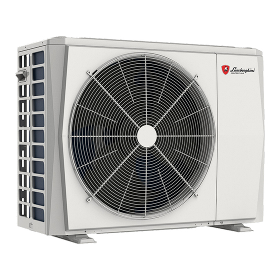
Related Manuals for Lamborghini Caloreclima IDOLA UE 3.2


Summary of Contents for Lamborghini Caloreclima IDOLA UE 3.2
- Page 1 IDOLA UE 3.2 UNITA' ESTERNE PER POMPE DI CALORE REVERSIBILI OUTDOOR UNITS FOR REVERSIBLE HEAT PUMPS MANUALE DI INSTALLAZIONE E USO INSTALLATION AND OWNER’S MANUAL...
-
Page 2: Table Of Contents
INDICE CONSIDERAZIONI DI SICUREZZA ACCESSORI Accessori forniti in dotazione con l'unità PRIMA DELL’INSTALLAZIONE INFORMAZIONI IMPORTANTI PER IL REFRIGERANTE SITO DI INSTALLAZIONE Selezione di una località in climi freddi Prevenire il sole PRECAUZIONI PER L'INSTALLAZIONE Dimensioni Requisiti per l'installazione Posizione del foro di scarico Requisiti di spazio per l'installazione 7 INSTALLAZIONE DEL TUBO DI COLLEGAMENTO Tubazione del refrigerante... - Page 3 PANORAMICA DELL’UNITÀ Smontare l'unità Scatola di controllo elettronico Unità Monofase 4~16kW Unità Trifase 12~16kW ESECUZIONE DEL TEST 11 PRECAUZIONI SULLA PERDITA DI REFRIGERANTE CONSEGNA AL CLIENTE FUNZIONAMENTO E PRESTAZIONI Strumentazione di protezione 13.1 13.2 Informazioni sull’interruzione di corrente 13.3 Capacità di riscaldamento 13.4 Funzione di protezione del compressore 13.5...
- Page 4 8/10 kW 4/6 kW Schema di cablaggio: 8/10kW per esempio Impianto di controllo elettrico 4/6 kW Sistema di refrigerazione Si prega di rimuovere la piastra cava successivamente all'installazione. 12/14/16 kW 8/10 kW Eliminare il supporto di trasporto 12/14/16 kW NOTA Si prega come prima cosa di rimuovere il coperchio di isolamento acustico del compressore.
-
Page 5: Precauzioni Di Sicurezza
1 PRECAUZIONI DI SICUREZZA Le precauzioni qui elencate sono suddivise nei seguenti tipi. Sono abbastanza importanti, quindi è necessario seguirle con attenzione. Significato dei simboli di PERICOLO, ATTENZIONE, ATTENZIONE e NOTA. INFORMAZIONI • Leggere attentamente queste istruzioni prima dell'installazione. Tenere questo manuale a portata di mano per future consultazioni. - Page 6 PERICOLO • Prima di toccare le componenti dei terminali elettrici, si prega di spegnere l'interruttore di alimentazione. • Quando i pannelli di servizio vengono rimossi, è molto facile, per sbaglio, toccare le componenti sotto tensione. • Non lasciare mai l'unità incustodita in fase di installazione o manutenzione quando il pannello di servizio viene rimosso.
- Page 7 • Non installare l'unità nei seguenti luoghi: - Dove c'è nebbia di olio minerale, spray di olio o vapori. Le componenti in plastica si possono deteriorare e causare il distacco o la fuoriuscita di acqua. - Dove si producono gas corrosivi (come il gas acido solforoso). Dove la corrosione dei tubi di rame o delle parti saldate può...
-
Page 8: Accessori
2 ACCESSORI 2.1 Accessori forniti in dotazione con l'unità Raccordi per l'installazione Forma Quantità Nome Manuale di installazione e uso dell'unità esterna e manuale del proprietario (il presente libro) Manuale dei dati tecnici Assemblaggio del tubo di collegamento dell'uscita dell'acqua Etichetta energia 3 PRIMA DELL’INSTALLAZIONE Prima dell’installazione... -
Page 9: Informazioni Importanti Per Il Refrigerante
2. Durante la manipolazione dell'unità tenere entrambi i lati dell'imbrago a livello. tenere la schiena dritta 3. Dopo aver montato l'unità, rimuovere l'imbrago dall'unità tirando 1 lato dell'imbrago. ATTENZIONE • Al fine di evitare lesioni, non toccare l'ingresso dell'aria e le alette di alluminio dell'unità. •... -
Page 10: Sito Di Installazione
Volume del refrigerante caricato in fabbrica nell'unità Modello Refrigerante/kg Tonnellate di CO equivalente Monofase 12kW 1,84 1,24 Monofase 14kW 1,84 1,24 Monofase 16kW 1,84 1,24 Trifase 12kW 1,84 1,24 Trifase 14kW 1,84 1,24 Trifase 16kW 1,84 1,24 ATTENZIONE - Frequenza dei controlli di perdite del refrigerante - La strumentazione che contiene meno di 3 kg di gas fluorurati ad effetto serra o le apparecchiature sigillate ermeticamente, che sono etichettate di conseguenza e contengono meno di 6 kg di gas fluorurati ad effetto serra, non sono soggette a controlli di tenuta. -
Page 11: Selezione Di Una Località In Climi Freddi
5.1 Selezione di una località nei climi freddi In condizioni normali, fare riferimento alle figure seguenti per l'installazione dell'unità: Cfr. la sezione "Manipolazione" nella sezione "3 Prima dell'installazione” (parete od ostacolo) NOTA Quando si utilizza l'unità in climi freddi, >300 Ingresso aria assicurarsi >300... -
Page 12: Precauzioni Per L'installazione
6 PRECAUZIONI DI INSTALLAZIONE 6.1 Dimensioni 8/10/12/14/16 kW (unità: mm) 4/6 kW (unità: mm) Fig: 6-1 Fig: 6-2 Modello 4/6kW 1008 8/10/12/14/16kW 1118 6.2 Requisiti di installazione • Controllare la resistenza e il livello del terreno di installazione in modo che l'unità non causi vibrazioni o emetta rumori in fase di funzionamento. -
Page 13: Posizione Del Foro Di Scarico
6.3 Posizione del foro di scarico Foro di scarico Foro di scarico Questo foro di scarico è coperto da un tappo di gomma. Se il foro di scarico piccolo non può soddisfare i requisiti di scarico, si può utilizzare contemporaneamente il foro di scarico grande. -
Page 14: Installazione Del Tubo Di Collegamento
<1/2 H Fig: 6-7 Unità A (mm) B1 (mm) B2 (mm) C (mm) 4~16kW ≥3000 ≥2000 ≥150 ≥600 2) In caso di installazione di più unità in collegamento laterale per fila. <1/2 H ≥500mm ≥500mm Fig: 6-8 A (mm) B1 (mm) B2 (mm) C (mm) Unità... -
Page 15: Rilevamento Delle Perdite
ATTENZIONE • Si prega di prestare attenzione ed evitare i componenti in cui vi è un collegamento ai tubi di collegamento. • Per evitare che le tubazioni del refrigerante si ossidino all'interno durante la saldatura, è necessario caricare l'azoto, o l'ossido ostruirà il sistema di circolazione. 7.2 Rilevamento delle perdite Usare acqua saponata o un prodotto rilevatore di perdite per controllare ogni giunzione, a prescindere dal fatto che ci sia che una perdita o meno (cfr. -
Page 16: Metodo Di Collegamento
7.4 Metodo di collegamento Unità esterna Unità interna Figure 7-5 Modellos 4~16 kW Lunghezza massima della tubazione (H+L1) Differenza di altezza massima (H) 1) Dimensione dei tubi del lato Gas e del lato Liquido MODELLO Refrigerante Lato gas/lato liquido 4/6kW Φ15,9/Φ6,35 8/10kW Φ15,9/Φ9,52... -
Page 17: Rimuovere La Sporcizia O L'acqua Nel Tubo
7.5 Rimuovere lo sporco o l'acqua nei tubi 1) Assicurarsi che non vi siano sporcizia o acqua prima di collegare le tubazioni alle unità esterne ed interne. 2) Lavare le tubazioni con azoto ad alta pressione, non utilizzare mai il refrigerante dell'unità esterna. 7.6 Test di tenuta all'aria Caricare l'azoto in pressione dopo aver collegato i tubi dell'unità... -
Page 18: Cablaggio Dell'unità Esterrna
8 CABLAGGIO DELL’UNITÀ ESTERNA AVVERTENZA Un interruttore principale o un altro mezzo di scollegamento, con separazione dei contatti in tutti i poli, deve essere incorporato nel cablaggio fisso in conformità con le leggi e le normative locali in materia. Spegnere l'alimentazione prima di effettuare qualsiasi collegamento. -
Page 19: Requisito Del Dispositivo Di Sicurezza
8.3 Requisito del dispositivo di sicurezza 1. Selezionare i diametri dei cavi (valore minimo) singolarmente per ogni unità in base alla tabella 8-1 e alla tabella 8-2, dove la corrente nominale nella tabella 9-1 significa MCA nella tabella 9-2. Nel caso in cui l'MCA superi i 63A, i diametri dei fili devono essere selezionati in base alla normativa nazionale sul cablaggio. -
Page 20: Per Completare L'isolamento Delle Unità Esterne
L2 L3 ALIMENTAZIONE ALIMENTAZIONE UNITÀ ESTERNA UNITÀ ESTERNA Monofase Trifase NOTA L'interruttore differenziale di terra predefinito deve essere un interruttore ad alta velocità di 30 mA (<0,1 s). Si prega di utilizzare un cavo schermato a 3 conduttori. 8.5 Per terminare l'installazione dell'unità esterna isolare e fissare le tubazioni del refrigerante e il cavo di interconnessione come segue: Tubo del gas Isolamento del tubo del gas... -
Page 21: Scatola Di Controllo Elettronico
4/6kW 8/10/12/14/16kW Porta 1 Per accedere al compressore e alle Porta 1 Per accedere al compressore e alle componenti elettriche. componenti elettriche AVVERTENZA • Spegnere completamente l'alimentazione - cioè l'alimentazione dell'unità e l'alimentazione del riscaldatore di riserva e dell'accumulatore dell'acqua calda sanitaria (se applicabile) - prima di procedere alla rimozione degli sportelli 1. •... - Page 22 PCB A PCB B 12/14/16kW Monofase (Indietro) CN30 PCB A PCB B PCB C 12/14/16kW Trifase NOTA L'immagine è unicamente a fini di riferimento, si prega di guardare il prodotto reale.
-
Page 23: Unità Monofase 4~16Kw
9.3 Unità Monofase 4~16kW 1) PCB A, modulo inverter Note: per 4-6kw, due condensatori CN20 Codifica Unità di montaggio Codifica Unità di montaggio Porta di collegamento del compressore U Riservata(CN302) Porta di collegamento del compressore V Porta per la comunicazione con il PCB B (CN32) Porta di collegamento del compressore W Porta d'ingresso N per ponte raddrizzatore(CN502) Porta di uscita per +12V/9V (CN20) - Page 24 3) PCB B, 4-16kw,Scheda di controllo principale CN10 CN27 CN11 CN22 CN24 CN17 CN26 CN28 CN13 CN55 CN18 CN14 CN7 CN5 CN6 CN16 CN19 CN21 CN29 CN33 CN2 CN30 CN36 CN37 CN38 CN20 26 25 24 Codifica Unità di montaggio Codifica Unità...
-
Page 25: Unità Trifase 12~16Kw
9.4 Unità Trifase 12~16kW 1) PCB A, modulo inverter CN16 CN22 CN15 CN23 CN17 CN18 CN20 CN19 Codifica Unità di montaggio Unità di montaggio Codifica Porta di ingresso P_in per modulo IPM (CN1) Porta di uscita per +15V(CN20) Porta di collegamento del compressore W (CN19) Porta per la comunicazione con PCB B (CN8) Scheda PED (CN22) Porta di collegamento del compressore V (CN18) - Page 26 2) PCB B, scheda di controllo principale CN41 CN26 CN24 CN36 CN21 CN18 CN31 CN29 CN10 CN35 CN11 CN28 CN20 CN37 CN27 V i n CN22 CN30 CN38 CN53 CN109 Unità di montaggio Unità di montaggio Codifica Codifica Porta per il cavo di terra (CN38) Porta per il sensore di temperatura Tp (CN8) Porta per sensore di temperatura ambiente esterno e Porta per la valvola a 2 vie 6(CN27)
- Page 27 3) PCB C, scheda filtro CN204 CN205 CN206 CN30 CN213 CN214 CN202 CN211 CN203 CN200 CN201 CN212 PCB C Trifase 12/14/16kW Codifica Unità di montaggio Codifica Unità di montaggio Alimentazione L2(CN201) Filtraggio di potenza L3 (L3’) Alimentazione L3(CN200) Filtraggio di potenza L2 (L2’) Alimentazione N(CN203) Filtraggio di potenza L1 (L1’) Porta di alimentazione per la scheda di controllo...
-
Page 28: Esecuzione Del Test
10 ESECUZIONE DEL TEST Operare secondo i "punti chiave per il funzionamento di prova" sul coperchio del quadro elettrico di comando. ATTENZIONE • Il test non può iniziare fino a che l'unità esterna non sarà stata collegata all'alimentazione per 12 ore. •... -
Page 29: Consegna Al Cliente
Unità interna Unità esterna La stanza è piena di refrigerante che perde. (Tutto il refrigerante è fuoriuscito.) 8/10/12/14/16 kW Fig.11-2 Unità interna A. Presa di ventilazione B. Allarme perdite relative alla ventola meccanica (La sirena per il rilevamento delle perdite deve essere installata in luoghi dove è... - Page 30 AVVERTENZA • Spegnere gli eventuali dispositivi di riscaldamento a • Rivolgersi al proprio rivenditore per l'installazione della combustibile, ventilare la stanza e contattare il pompa di calore. rivenditore presso il quale è stato acquistato il Un’installazione incompleta eseguita dall’utente potrebbe dispositivo.
-
Page 31: Funzionamento E Prestazioni
NOTA • Non esporre mai bambini, piante o animali Quando si avvia il dispositivo di protezione, si prega di direttamente al flusso dell’aria. spegnere il interruttore di alimentazione manuale, e riavviare Ne può derivare un'influenza negativa su bambini piccoli, il funzionamento dopo che il problema è stato risolto. animali e piante. -
Page 32: Codici Di Errore
13.8 Codici di errore Quando viene attivato un dispositivo di sicurezza, sull'interfaccia utente viene visualizzato un codice di errore. La tabella sottostante presenta un elenco di tutti gli errori e delle azioni correttive. Resettare la sicurezza spegnendo e riaccendendo l'unità. Nel caso in cui questa procedura di ripristino della sicurezza non abbia successo, contattare il proprio rivenditore locale. - Page 33 ANOMALIA DI CODICE CAUSA DEL GUASTO E AZIONE CORRETTIVA FUNZIONAMENTO O ERRORE PROTEZIONE 1. Vento forte o tifone in basso verso la ventola, per far funzionare la ventola in direzione opposta. Modificare la direzione dell'unità o creare riparo per evitare che il tifone si trovi al di sotto della ventola.
- Page 34 ANOMALIA DI CODICE CAUSA DEL GUASTO E AZIONE CORRETTIVA FUNZIONAMENTO O ERRORE PROTEZIONE Modalità di riscaldamento, modalità ACS: 1. Il flusso d'acqua è basso; la temperatura dell'acqua è alta, se c’è aria nel sistema idrico. Rilasciare l'aria. 2. La pressione dell'acqua è inferiore a 0.1Mpa, caricare l'acqua per lasciare la pressione nel range 0.15~0.2Mpa.
- Page 35 ANOMALIA DI CODICE CAUSA DEL GUASTO E AZIONE CORRETTIVA FUNZIONAMENTO O ERRORE PROTEZIONE 1. Il coperchio dello scambiatore di calore non viene rimosso. Toglierlo. Protezione ad alta 2. Lo scambiatore di calore è sporco o qualcosa è bloccato in temperatura della temperatura superficie.
- Page 36 ANOMALIA DI CODICE FUNZIONAMENTO O CAUSA DEL GUASTO E AZIONE CORRETTIVA ERRORE PROTEZIONE Protezione del modulo Protezione a bassa tensione del generatore DC Protezione ad alta pressione del sistema a pompa di calore Protezione ad alta tensione del generatore DC Protezione ad alta pressione del sistema a pompa di calore 1.
-
Page 37: Technical Specifications
14 TECHNICAL SPECIFICATIONS Model 10kW Alimentazione 220-240V~50Hz Ingresso corrente nominale 3300W 3600W 2200W 2600W Corrente nominale 10,5A 12,0A 14,5A 16,0A Capacità nominale Rimandiamo ai dati tecnici Dimensioni (larghezza × 1008*712*426 1118*865*523 altezza × profondità)[mm] Confezione (larghezza × 1065*800*485 1180*890*560 altezza × profondità)[mm] Motore della ventola Motore CC / Orizzontale Compressore... - Page 38 Modello 12kW 14kW 16kW 12kW 14kW 16kW Trifase Trifase Trifase 380-415V 3N~ 50Hz Alimentazione 220-240V~ 50Hz Ingresso corrente nominale 6100W 5400W 5700W 6100W 5400W 5700W 11,0A Corrente nominale 24,5A 25.0A 26,0A 10,0A 9,0A Rimandiamo ai dati tecnici Capacità nominale Dimensioni (larghezza × 1118*865*523 1118*865*523 altezza ×...
-
Page 39: Informazioni Sulla Manutenzione
15 INFORMAZIONI DI MANUTENZIONE 1) Controlli nella zona Prima di iniziare i lavori su impianti contenenti refrigeranti infiammabili sarà necessario eseguire controlli di sicurezza al fine di garantire che il rischio di accensione sia ridotto al minimo. Per eseguire interventi di riparazione dell'impianto di refrigerazione, prima di effettuare lavori sull'impianto devono sarà... - Page 40 b) Sarà necessario prestare particolare attenzione a quanto segue al fine di garantire che, lavorando sulle componenti elettriche, l'involucro non venga alterato in modo tale da modificare il livello di protezione. Ciò include danni ai cavi, numero eccessivo di collegamenti, morsetti non conformi alle specifiche originali, danni alle guarnizioni, montaggio errato dei pressacavi, ecc.
- Page 41 • Le bombole devono essere tenute in posizione verticale. • Assicurarsi che l'impianto di refrigerazione sia collegato alla messa a terra prima di caricare il sistema con il refrigerante. • Etichettare il sistema quando la carica è completa (a meno che ciò non sia già stato fatto). •...
- Page 42 ALLEGATO A: Ciclo del refrigerante Raffreddamento Caldo Descrizione Descrizione Elemento Elemento Compressore Sensore dello scambiatore esterno Valvola a 4 vie Valvola di arresto (gas) Separatore gas-liquido Valvola di arresto (liquido) Scambiatore di calore lato aria Pressostato di alta pressione Valvola di espansione elettronica Interruttore a bassa pressione Valvola elettromagnetica mono-via Sensore di pressione...
- Page 43 ALLEGATO B: Schema di cablaggio con controllo elettrico 4/6/8/10kW IMPOSTAZIONE S6-1 S6-2 S6-3 DI FABBRICA CN20 CN19 Ventola PCB A, Scheda W(C) NERO inverter per V(S) ROSSO monofase U(R) 10KW CN501 CN502 L'immagine del cablaggio COMP mostrata è unicamente a scopo di riferimento, il prodotto reale può...
- Page 44 ALLEGATO C: Schema cablaggio controllato elettricamente 12/14/16kW IMPOSTAZIONE S6-1 S6-2 S6-3 DI FABBRICA CN20 CN32 Ventola 12KW 14KW PCB A, Scheda W(C) NERO inverter per 16KW V(S) ROSSO monofase U(R) L'immagine del cablaggio CN502 CN501 mostrata è unicamente a scopo di riferimento, il prodotto reale può...
- Page 45 Allegato D: Schema cablaggio controllato elettricamente Trifase 12/14/16kW ROSSO NERO NERO CN16 NERO H-SEN MARRONE ROSSO MARRONE MARRONE GRIGIO SCHEDA DRIVER CN15 CN41 CN26 CN19 CN24 CN4 CN6 CN32 COMPRESSORE GRIGIO Nucleo in ferrite POTENZA H-SEN L-SEN ROSSO CN17 GRIGIO O-COMP CN36 NERO...
- Page 46 ALLEGATO C: Per installare il nastro riscaldante elettrico alla presa di scarico (a cura del cliente) Collegare il nastro riscaldante all’uscita di scarico al giunzione XT3. Al nastro riscaldante 4/6kW dell'uscita di scarico NOTA L'immagine è unicamente a fini di riferimento, si prega di guardare il prodotto reale.
- Page 47 12/14/16kW Monofase Al nastro riscaldante dell'uscita di scarico NOTA L'immagine è unicamente a fini di riferimento, si prega di guardare il prodotto reale. L’alimentazione del nastro riscaldante non supererà i 40W/200mA, tensione di alimentazione 230VAC. 12/14/16kW Trifase...
-
Page 48: Certificato Di Garanzia
Dopo la verifica della documentazione, un Servizio Assistenza autorizzato Lamborghini Caloreclima contatterà il Cliente e/o l’Installatore per concordare l’intervento gratuito di verifica iniziale del prodotto e la convalida, tramite registrazione, della garanzia convenzionale. Trascorsi 10 giorni dalla messa in servizio la presente Garanzia Convenzionale non sarà... - Page 49 CONTENTS SAFETY PRECAUTIONS ACCESSORIES Accessories supplied with the unit BEFORE INSTALLATION IMPORTANT INFORMATION FOR THE REFRIGERANT INSTALLATION SITE Selecting a location in cold climates Prevent sunshine INSTALLATION PRECAUTIONS Dimensions Installation requirements Drain hole position Installation space requirements 7 INSTALLATION THE CONNECTING PIPE Rrfrigerant piping Leakage detection Heat insulation...
- Page 50 OVERVIEW OF THE UNIT Disassambling the unit Electronic control box 4~16kW 1-phase units 12~16kW 3-phase units TEST RUNNING 11 PRECAUTIONS ON REFRIGERANT LEAKAGE TURN OVER TO CUSTOMER OPERATION AND PERFORMANCE 13.1 Protection equipment 13.2 About power cut 13.3 Heating capcity 13.4 Compressor protection feature 13.5...
- Page 51 4/6 kW 8/10/12/14/16 kW Wiring diagram:8/10kW for example Electric Control System 4/6 kW Refrigerant System Please remove the hollow plate after installation. 12/14/16 kW 8/10 kW Remove the transportation support 12/14/16 kW NOTE Please remove the noise insulation cover of the compressor first. Please make sure the transportation support had be removed.
-
Page 52: Safety Precautions
1 SAFETY PRECAUTIONS The precautions listed here are divided into the following types.They are quite important, so be sure to follow them carefully. Meanings of DANGER, WARNING, CAUTION and NOTE symbols. INFORMATION Read these instructions carefully before installation. Keep this manual in a handy for future peference. Improper installation of equipment or accessories may result in electric shock, short-circuit, leakage, fire or other damage to the equipment. - Page 53 DANGER Before touching electric terminal parts, turn off power switch. When service panels are removed, live parts can be easily touched by accident. Never leave the unit unattended during installation or servicing when the service panel is removed. Do not touch water pipes during and immediately after operation as the pipes may be hot and could burn your hands.
- Page 54 Do not install the unit in the following places: - Where there is mist of mineral oil, oil spray or vapors. Plastic parts may deteriorate, and cause them to come loose or water to leak. - Where corrosive gases (such as sulphurous acid gas) are produced. Where corrosion of copper pipes or soldered parts may cause refrigerant to leak.
-
Page 55: Accessories
2 ACCESSORIES 2.1 Accessories supplied with the unit Installation Fittings Shape Quantity Name Outdoor unit installation & owners manual (this book) Technical data manual Water outlet connection pipe assembly Energy label 3 BEFORE INSTALLATION Before installation Be sure to confirm the model name and the serial number of the unit. Handling 1. -
Page 56: Important Information For The Refrigerant
2. While handling the unit keep both sides of the sling level. keep your back straight 3. After mounting the unit,remove the sling from the unit by pulling 1 side of the sling. CAUTION To avoid injury, do not touch the air inlet and aluminum fins of the unit. Do not use the grips in the fan grills to avoid damage. -
Page 57: Installation Site
Factory charged refrigerant volume in the unit Model Refrigerant/kg Tonnes CO equivalent 1-phase 12kW 1.84 1.24 1-phase 14kW 1.84 1.24 1-phase 16kW 1.84 1.24 3-phase 12kW 1.84 1.24 3-phase 14kW 1.84 1.24 1.84 1.24 3-phase 16kW CAUTION Frequency of Refrigerant Leakage Checks - Equipment that contains less than 3 kg of fluorinated greenhouse gases or hermetically sealed equipment, which is labelled accordingly and contains less than 6 kg of fluorinated greenhouse gases shall not be subject to leak checks. -
Page 58: Selecting A Location In Cold Climates
5.1 Selecting a location in cold In normal condition,refer to the figures below for installation of the unit: climates Refer to "Handling" in section “4 Before installation” ( wall or obstacle ) NOTE When operating the unit in cold climates, be sure Air inlet >300 to follow the instructions described below. -
Page 59: Installation Precautions
6 INSTALLATION PRECAUTIONS 6.1 Dimensions 8/10/12/14/16 kW (unit: mm) 4/6 kW (unit: mm) Fig: 6-1 Fig: 6-2 Model 4/6kW 1008 8/10/12/14/16kW 1118 6.2 Installation requirements Check the strength and level of the installation ground so that the unit may not cause any vibrations or noise during the operation. -
Page 60: Drain Hole Position
6.3 Drain hole position Drain hole Drain hole This drain hole is covered by rubber plug. If the small drain hole can not meet the drainage requirements, the big one can be used at the same time. 8/10/12/14/16 kW 4/6 kW Fig: 6-5 CAUTION It's necessary to install an electrical heating belt if water can't drain out in cold weather even the big drain hole has... -
Page 61: Refrigerant Piping
<1/2 H Fig: 6-7 Unit A(mm) B1(mm) B2(mm) C(mm) 4~16kW ≥3000 ≥2000 ≥150 ≥600 2) In case of installing multiple units in lateral connection per row. <1/2 H ≥500mm ≥500mm Fig: 6-8 A(mm) B1(mm) B2(mm) C(mm) Unit 4~16kW ≥3000 ≥2000 ≥300 ≥600 7 INSTALL THE CONNECTING PIPE... -
Page 62: Leakage Detection
CAUTION ● Please pay attention to avoid the components where it is connecting to the connecting pipes. To prevent the refrigerant piping from oxidizing inside when welding, it is necessary to charge nitrogen, or oxide ● will chock the circulation system. 7.2 Leakage detection Use soap water or leakage detector to check every joint whether leak or not (Refer to Fig.7-2 ).Note: A is high pressure side stop valve... -
Page 63: Connecting Method
7.4 Connecting method Outdoor Unit Indoor Unit Figure 7-5 Models 4~16 kW Max.piping length (H+L1) Max difference in height (H) 1) Size of pipes of Gas side and Liquid side MODEL Refrigerant Gas side/Liquid side 4/6kW Φ15.9/Φ6.35 8/10kW Φ15.9/Φ9.52 1-phase 12/14/16kW Φ15.9/Φ9.52 3-phase 12/14/16kW Φ15.9/Φ9.52... -
Page 64: Remove Dirt Or Water In The Pipes
7.5 Remove dirt or water in the pipes 1) Make sure there is no any dirt or water before connectiong the piping to the outdoor and indoor units. 2) Wash the pipes with high pressure nitrogen, never use refrigerant of outdoor unit. 7.6 Airtight testing Charge pressured nitrogen after connecting indoor/outdoor unit pipes to do airtight testing. -
Page 65: Outdoor Unit Wiring
8 OUTDOOR UNIT WIRING WARNING A main switch or other means of disconnection, having a contact separation in all poles, must be incorporated in the fixed wiring in accordance with relevant local laws and regulations. Switch off the power supply before making any connections. -
Page 66: Safety Device Requirment
8.3 Safety device requirment 1. Select the wire diameters( minimum value) individually for each unit based on the table 8-1 and table 8-2, where the rated current in table 9-1 means MCA in table 9-2. In case the MCA exceeds 63A, the wire diameters should be selected according to the national wiring regulation. -
Page 67: To Finish The Outdoor Unit Insulation
L2 L3 OUTOOOR UNIT OUTOOOR UNIT POWER SUPPLY POWER SUPPLY 1-phase 3-phase NOTE The ground fault circuit interrupter must be a high-speed type breaker of 30 mA (<0.1 s). Please use 3-core shielded wire. 8.5 To finish the outdoor unit installation insulate and fix the refrigerant piping and interconnection cable as follows: Gas pipe Gas pipe insulation... -
Page 68: Electronic Control Box
4/6kW 8/10/12/14/16kW Door 1 To access to the compressor and Door 1 To access to the compressor and electrical parts. electrical parts WARNING Cut off all power supply— i.e. unit power supply and backup heater and domestic hot water tank power supply (if applicable) —... - Page 69 PCB A PCB B 12/14/16kW 1-phase (Back) CN30 PCB A PCB B PCB C 12/14/16kW 3-phase NOTE The picture is for reference only, please refer to the actual product.
-
Page 70: 16Kw 1-Phase Units
9.3 4~16kW 1-phase units 1) PCB A, 4-10kw,Inverter module Remarks: for 4-6kw, two capacitors CN20 Coding Assembly unit Coding Assembly unit Compressor connection port U Reserved(CN302) Compressor connection port V Port for communication with PCB B(CN32) Compressor connection port W Input port N for rectifier bridge(CN502) Output port for +12V/9V(CN20) Input port L for rectifier bridge(CN501) - Page 71 3) PCB B, 4-16kw,Main control board CN10 CN27 CN11 CN22 CN24 CN17 CN26 CN28 CN13 CN55 CN18 CN14 CN7 CN5 CN6 CN16 CN19 CN21 CN29 CN33 CN2 CN30 CN36 CN37 CN38 CN20 26 25 24 Coding Assembly unit Coding Assembly unit Output port L to PCB A(CN28) Port for low pressure switch (CN14) Port for communication with hydro-box control board...
-
Page 72: 16Kw 3-Phase Units
9.4 12~16kW 3-phase units 1) PCB A, Inverter module CN16 CN22 CN15 CN23 CN17 CN18 CN20 CN19 Coding Assembly unit Assembly unit Coding Output port for +15V(CN20) Input port P_in for IPM module (CN1) Compressor connection port W (CN19) Port for communication with PCB B (CN8) PED board(CN22) Compressor connection port V (CN18) Compressor connection port U (CN17) - Page 73 2) PCB B, Main control board CN41 CN26 CN24 CN36 CN21 CN18 CN31 CN29 CN10 CN35 CN11 CN28 CN20 CN37 CN27 V i n CN22 CN30 CN38 CN53 CN109 Coding Assembly unit Coding Assembly unit Port for temp.sensor Tp(CN8) Port for ground wire(CN38) Port for outdoor ambient temp.
- Page 74 3) PCB C, filter board CN204 CN205 CN206 CN30 CN213 CN214 CN202 CN211 CN203 CN200 CN201 CN212 PCB C 3-phase 12/14/16kW Coding Assembly unit Coding Assembly unit Power supply L2(CN201) Power filtering L3(L3’) Power supply L3(CN200) Power filtering L2(L2’) Power supply N(CN203) Power filtering L1(L1’) Power supply port of 310VDC(CN212) Power supply port for main control board(CN30)
-
Page 75: Test Running
10 TEST RUNNING Operate according to "key points for test running" on the electric control box cover. CAUTION ● Test running can not start until the outdoor unit has been connected to the power for 12 hours. ● Test running can not start until all the valves are affirmed open. ●... -
Page 76: Turn Over To Customer
Indoor Unit Outdoor Unit Room is filled of leakage refrigerant. (All refrigerant has leaked out.) 8/10/12/14/16 kW Fig.11-2 Indoor unit A. Ventilation peristome B. Leak alarm related to mechanical ventilator (Leak hunting siren should be installed in places easily keep refrigerant) Fig.11-3 Max. - Page 77 WARNING Turn off any combustible heating devices, ventilate the Ask your dealer for installation of the heat pump. room, and contact the dealer where you purchased the Incomplete installation performed by yourself may result in a unit. water leakage, electric shock, and fire. Do not use the heat pump until a service person confirms that the portion where the refrigerant leaks is repaired.
-
Page 78: Operation And Performance
NOTE Never expose little children, plants or animals directly to the air flow. When the protection equipment starts, please shut down the Adverse influence to little children, animals and plants may manual power switch, and restart operation after problem is result. -
Page 79: Error Codes
13.8 Error codes When a safety device is activated, an error code will be displayed on the user interface. A list of all errors and corrective actions can be found in the table below. Reset the safety by turning the unit OFF and back ON. In case this procedure for resetting the safety is not successful, contact your local dealer. - Page 80 ERROR MALFUNCTION FAILURE CAUSE CODE OR PROTECTION AND CORRECTIVE ACTION 1. Strong wind or typhoon below toward to the fan, to make the fan running in the opposite direction. Change the unit direction or make shelter to avoid typhoon below to the fan. The DC fan failure 2.fan motor is broken, change a new fan motor.
- Page 81 ERROR MALFUNCTION FAILURE CAUSE CODE OR PROTECTION AND CORRECTIVE ACTION Heating mode, DHW mode: 1. The water flow is low; water temp is high, whether there is air in the water system. Release the air. 2. Water pressure is lower than 0.1Mpa, charge the water to let the pressure in the range of 0.15~0.2Mpa.
- Page 82 ERROR MALFUNCTION FAILURE CAUSE CODE OR PROTECTION AND CORRECTIVE ACTION 1. Heat exchanger cover is not removed. Remove it. 2. Heat exchanger is dirty or something is block on the surface. High temperature protection of Clean the heat exchanger or remove the obstruction. refrigerant outlet temp of 3.
- Page 83 ERROR MALFUNCTION FAILURE CAUSE CODE OR PROTECTION AND CORRECTIVE ACTION Module protection DC generatrix low voltage protection Heat pump syserm high pressure protection DC generatrix high voltage protection Heat pump syserm high pressure protection 1. Check the Heat pump system pressure; 2.
-
Page 84: Technical Specifications
14 TECHNICAL SPECIFICATIONS Model 10kW 220-240V~ 50Hz Power supply Rated power input 3300W 3600W 2200W 2600W 16.0A Rated current 10.5A 12.0A 14.5A Refer to the technical data Norminal capacity Dimensions (W×H×D)[mm] 1008*712*426 1118*865*523 Packing (W×H×D)[mm] 1065*800*485 1180*890*560 DC motor / Horizontal Fan motor DC inverter dual rotary Compressor... - Page 85 Model 12kW 14kW 16kW 12kW 14kW 16kW 3-phase 3-phase 3-phase 380-415V 3N~ 50Hz Power supply 220-240V~ 50Hz Rated power input 6100W 5400W 5700W 6100W 5400W 5700W 11.0A Rated current 24.5A 25.0A 26.0A 10.0A 9.0A Refer to the technical data Norminal capacity Dimensions (W×H×D)[mm] 1118*865*523 1118*865*523...
-
Page 86: Information Servicing
15 INFORMATION SERVICING 1) Checks to the area Prior to beginning work on systems containing flammable refrigerants, safety checks are necessary to ensure that the risk of ignition is minmised. For repair to the refrigerating system, the following precautions shall be complied with prior to conducting work on the system. - Page 87 b) Particular attention shall be paid to the following to ensure that by working on electrical components, the casing is not altered in such a way that the level of protection is affected. This shall include damage to cables, excessive number of connections, terminals not made to original specification, damage to seals, incorrect fitting of glands, etc.
- Page 88 Cylinders shall be kept upright. Ensure that the refrigeration system is earthed prior to charging the system with refrigerant. Label the system when charging is complete(if not already). Extreme care shall be taken not to overfill the refrigeration system. Prior to recharging the system it shall be pressure tested with OFN. The system shall be leak tested on completion of charging but prior to commissioning.
- Page 89 ANNEX A: Refrigerant cycle Cooling Heating Item Description Item Description Compressor Outdoor exchanger sensor 4-Way Valve Stop valve (gas) Gas-liquid separator Stop valve (liquid) Air side heat exchanger High Pressure Switch Electronic expansion Valve Low Pressure Switch Single-way electromagnetic valve Pressure sensor Filter Capillary...
- Page 90 ANNEX B: Electrically controlled wiring diagram 4/6/8/10kW FACTORY S6-1 S6-2 S6-3 SETTING CN20 CN19 BLUE W(C) BLACK PCB A,Inverter V(S) board for 1phase U(R) 10KW CN501 CN502 COMP The wiring picture shown is for reference only,actual product may vary. BROWN CN27 BLUE BLUE...
- Page 91 ANNEX C: Electrically controlled wiring diagram 12/14/16kW FACTORY S6-1 S6-2 S6-3 SETTING CN20 CN32 12KW 14KW BLUE W(C) BLACK PCB A,Inverter 16KW V(S) board for 1phase U(R) The wiring picture shown CN502 CN501 is for reference only,actual product may vary. COMP BLUE BROWN...
- Page 92 Annex D: Electrically controlled wiring diagram 3-phase 12/14/16kW BLACK BLACK CN16 BLACK H-SEN BROWN BROWN BROWN GRAY CN15 CN41 CN26 CN19 CN24 CN4 CN6 CN32 GRAY POWER H-SEN L-SEN CN17 GRAY O-COMP CN36 POWER-I CN18 CN21 DSP1 CN20 CN19 CN18 1 2 3 1 2 3 CN33...
- Page 93 ANNEX C: To install the E-heating tape at the drainage outlet (by client) Connect the wireCeating tape at the drainage outlet to the wire joint XT3. 4/6kW To the heating tape of drainage outlet NOTE The picture is for reference only, please refer to the actual product.
- Page 94 12/14/16kW 1-phase To the heating tape of drainage outlet NOTE The picture is for reference only, please refer to the actual product. The power of the E-heating tape shall not exceed 40W/200mA, supply volatge 230VAC. 12/14/16kW 3-phase...
- Page 96 Lamborghini Caloreclima – www.lamborghinicalor.it è un marchio commerciale di FERROLI S.p.A. - Via Ritonda 78/a 37047 San Bonifacio (Verona) Italy - tel. +39.045.6139411 - fax. +39.045.6100933 www.ferroli.com Fabbricato in Cina - Made in China...
Need help?
Do you have a question about the IDOLA UE 3.2 and is the answer not in the manual?
Questions and answers