Panasonic PT-DW730ULS Operating Instructions Manual
Panasonic pt-dw730uls: user guide
Hide thumbs
Also See for PT-DW730ULS:
- Specification (15 pages) ,
- Dimensional drawing (1 page) ,
- Brochure (4 pages)
Table of Contents
Advertisement
Thank you for purchasing this Panasonic product.
■ This manual is common to all the models regardless of suffixes of the Model No.
z S: Silver model, the standard zoom lens supplied
K: Black model, the standard zoom lens supplied
■ Before operating this product, please read the instructions carefully and save this manual
for future use.
■ Before using your projector, be sure to read "Read this first!" (
W0711SM0 -YI
Operating Instructions
DLP
TM
Projector
PT-DW730U
Model No.
LS: Silver model, the lens sold separately
LK: Black model, the lens sold separately
Functional Manual
Commercial Use
PT-DW730UL
PT-DX800U
PT-DX800UL
pages 2 to 8)
ENGLISH
TQBJ0379
Advertisement
Table of Contents

Related Manuals for Panasonic PT-DW730ULS


Summary of Contents for Panasonic PT-DW730ULS
-
Page 1: Operating Instructions
PT-DW730UL PT-DX800U PT-DX800UL Thank you for purchasing this Panasonic product. ■ This manual is common to all the models regardless of suffixes of the Model No. z S: Silver model, the standard zoom lens supplied LS: Silver model, the lens sold separately... -
Page 2: Read This First
Information Read this first! Read this first! WARNING: TO REDUCE THE RISK OF FIRE OR ELECTRIC SHOCK, DONOT EXPOSE THIS PRODUCT TO RAIN OR MOISTURE. The lightning flash with arrowhead symbol, within an equilateral triangle, is intended to alert the user to the presence of uninsulated “dangerous voltage”... - Page 3 FCC NOTICE (USA) Declaration of Conformity Model Number: PT-DW730U/PT-DW730UL/PT-DX800U/PT-DX800UL Trade Name: Panasonic Responsible Party: Panasonic Corporation of North America Address: One Panasonic Way, Secaucus, NJ 07094 Telephone number: (877)803-8492 E-mail: projectorsupport@us.panasonic.com This device complies with Part 15 of the FCC Rules.
- Page 4 Read this first! WARNING: „ POWER The wall outlet or the circuit breaker shall be installed near the equipment and shall be easily accessible when problems occur. If the following problems occur, cut off the power supply immediately. Continued use of the projector in these conditions will result in fire or electric shock. z If foreign objects or water get inside the projector, cut off the power supply.
- Page 5 If liquid enters inside of the projector, consult your dealer. z Particular attention must be paid to children. Use the ceiling mount bracket specified by Panasonic. Defects in the ceiling mount bracket will result in falling accidents. z Attach the supplied safety cable to the ceiling mount bracket to prevent the projector from falling down.
- Page 6 Read this first! WARNING: „ ACCESSORIES Do not use or handle the batteries improperly, and refer to the following. Failure to observe this will cause burns, batteries to leak, overheat, explode or catch fire. z Do not use unspecified batteries. z Do not disassemble dry cell batteries.
- Page 7 Read this first! CAUTION: „ ON USE/INSTALLATION Do not put your weight on this projector. You could fall or the projector could break, and injury will result. z Be especially careful not to let young children stand or sit on the projector. Do not place the projector in extremely hot locations.
- Page 8 Read this first! Brazil Only Brasil Apenas „ Manuseio de baterias usadas BRASIL Após o uso, as pilhas e /ou baterias poderão ser entregues ao estabelecimento comercial ou rede de assistência técnica autorizada. Cobrir os terminais positivo (+) e negativo (-) com uma fita isolante adesiva, antes de depositar numa caixa destinada para o recolhimento.
- Page 9 Feature of the Projector Feature of the Projector Quick Steps Quick Steps For details, see the corresponding pages. High clarity and high color reproducibility 1. Set up your projector. page 21) ▶The unique optical system and lamp boost control realizes high clarity and high color reproducibility.
-
Page 10: Table Of Contents
Contents Contents Be sure to read “Read this first!”. ( pages 2 to 8) Adjustment range by the lens position shift Important Information (optical shift) ..........37 Basic operations using the remote control ... 38 Read this first! ..........2 Using the SHUTTER function ......38 Precautions for Use........12 Using the on-screen display function ....38... - Page 11 Contents [AUTO SIGNAL] ..........57 Maintenance [AUTO SETUP] ..........57 [DVI-D IN] ............58 LAMP/TEMP/FILTER Indicators ....87 [ON-SCREEN DISPLAY] .........58 Managing the indicated problems ....87 [BACK COLOR] ..........59 Maintenance/Replacement ....... 89 [STARTUP LOGO] ..........60 Before maintaining/replacing the unit ....89 [FREEZE] ............60 Maintenance ...........89 [SIDE BY SIDE] (PT-DW730U only) ....60 Replacing the unit ...........90 [PROJECTOR SETUP] menu ....61...
-
Page 12: Precautions For Use
Precautions for Use Precautions for Use Cautions when transporting z Projection lens is susceptible to effects due to vibration or impact. Make sure to remove the lens when transporting. z When transporting the projector, hold it securely by its bottom and avoid excessive vibration and impacts. Doing so may damage the internal parts and result in malfunctions. - Page 13 Precautions for Use ■ Do not use the projector tilted right or left. Using the projector at a vertical angle that exceeds 15° may reduce product life or result in malfunction. ■ When installing and using the projector at an angle that exceeds 30° vertically, set [COOLING CONDITION] ( ...
-
Page 14: Security
Make your password as difficult to guess as possible. z Change your password periodically. z Panasonic or its affiliate company never inquires a password directly to a customer. Do not tell your password in case you receive such an inquiry. -
Page 15: Cautions On Use
LICENSE and GNU LESSER GENERAL PUBLIC LICENSE respectively. As for the terms and conditions, please refer to the software licence of the supplied CD-ROM. If you wish to ask any questions as to the software, please contact (sav.pj.gpl.pavc@ml.jp.panasonic.com) by email. ENGLISH - 15... -
Page 16: Accessories
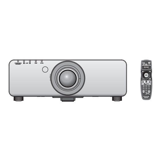
Precautions for Use Accessories Make sure that the following accessories are provided with your projector. Numbers in the brackets ( ) show the number of accessories. Wireless/wired remote Power cord (x1) Projection lens cover (x1) Lens cover (x1) control unit (x1) (K2CG3YY00075) (TKPB35101) (TKKL5244) -
Page 17: About Your Projector
About Your Projector About Your Projector Remote control ■ Top (1) Remote control indicator Flashes by pressing any buttons. Remote control signal emitters (2) STANDBY ( ) button Sets the projector to the standby mode when the <MAIN POWER> switch on the projector is set to <ON>. -
Page 18: Projector Body
About Your Projector Projector body ■ Front Power indicator <STANDBY (RED)/ON (GREEN)> Displays the status of the power. (1) (2) (3) (4) (5) Lamp indicator <LAMP1> Displays the status of the lamp 1. Lamp indicator <LAMP2> Displays the status of the lamp 2. Temperature indicator <TEMP>... -
Page 19: Control Panel
About Your Projector ■ Control panel (10) (11) (12) (13) (1) STANDBY ( (9) <MENU> button ) button Sets the projector to the standby mode when the <MAIN Displays and clears the main menu, and returns to the POWER> switch on the projector is set to <ON>. previous menu when the menu is displayed. -
Page 20: Using Remote Control
Using Remote control Using Remote control Inserting and removing the Note z Set the ID number of the projector from the batteries [PROJECTOR SETUP] menu [PROJECTOR ID] page 61). 1) Open the cover. Connecting to the projector (ii) with a cable When you use the system with multiple projectors, configure the units as in the following figure. -
Page 21: Setting Up
Setting up Setting up Projection method You can use the projector with any of the following four projection methods. Select the appropriate method depending on the environment. ■ Mounting on the ceiling and ■ Setting on a desk/floor and projecting forward projecting from rear (Using the translucent screen) Menu item... -
Page 22: Screen Size And Throw Distance
Setting up Screen size and throw distance Install the projector referring to the following figures and table describing projection distances. Image size and image position can be adjusted in accordance with the screen size and screen position. Projected image Screen L (LW/LT) L (LW/LT) Screen... - Page 23 Setting up ■ Projection distance per projection lens (for PT-DW730U) z When the screen aspect ratio is 16:10 (unit: m) (All measurements below are approximate and may differ slightly from the actual measurements.) Optional lens Standard Lens type Fixed- Ultra short- Short-focus Medium-focus Long-focus...
- Page 24 Setting up z When the screen aspect ratio is 4:3 (unit: m) (All measurements below are approximate and may differ slightly from the actual measurements.) Optional lens Standard Lens type Fixed- Ultra short- Short-focus Medium-focus Long-focus Ultra long-focus zoom lens focus lens focus zoom lens zoom lens...
- Page 25 Setting up ■ Projection distance per projection lens (for PT-DX800U) z When the screen aspect ratio is 4:3 (unit: m) (All measurements below are approximate and may differ slightly from the actual measurements.) Optional lens Standard Lens type Height position (H) Fixed- Ultra short- Short-focus...
- Page 26 Setting up ■ Projection distance calculation formula per projection lens (for PT-DW730U) Lens type Aspect ratio Projection distance (L) formula Min. (LW) L = 1.5669 x SD (m) – 0.0746 16:10 Max. (LT) L = 2.1850 x SD (m) – 0.0725 Min.
-
Page 27: Adjustable Feet
Setting up ■ Projection distance calculation formula per projection lens (for PT-DX800U) Lens type Aspect ratio Projection distance (L) formula Min. (LW) L = 1.4567 x SD (m) – 0.0746 Max. (LT) L = 2.0354 x SD (m) – 0.0725 Standard zoom lens –... -
Page 28: Removing/Attaching The Projection Lens
Removing/attaching the projection lens Removing/attaching the projection lens Perform the following steps when removing/attaching the standard zoom lens or the optional lens. Move the lens to the home position before replacing or removing the lens. ( page 36) Attention z Replace the projection lens after turning off the power of the projector. -
Page 29: Attaching The Projection Lens
Removing/attaching the projection lens Attaching the projection lens 1) Remove the projection lens cover, align the guide of the projection lens to the guide groove on the projector, and then insert the projection lens. Groove Guide Projection lens 2) Turn the projection lens clockwise until it clicks. 3) Attach the projection lens cover aligning the marking (groove *1) to the tip of the arrow on the projector (*2), and then turn and secure the projection lens cover until the *1 groove aligns with the *3 marking. -
Page 30: Connections
Connections Connections Before connecting to the projector z Read carefully the instruction manual for the device to be connected. z Turning off the power switch of the devices before connecting cables. z If any connection cable is not supplied with the device, or if no optional cable is available for the connection of the device, prepare a necessary system connection cable to suit the device. -
Page 31: Connecting Example: Av Equipment
Connections Connecting example: AV equipment DVD player with HDMI VCR (TBC terminal (HDCP) built-in) Attention z Always use one of the following when connecting a VCR. – A VCR with built-in time base corrector (TBC) – A time base corrector (TBC) between the projector and the VCR z If nonstandard burst signals are connected, the image may be distorted. -
Page 32: Powering On/Off
Powering ON/OFF Powering ON/OFF Connecting the power cord Be sure to insert the supplied power cord securely to its base to prevent it from coming off. Confirm that the <MAIN POWER> switch is at the <OFF> side, before connecting the power cord. ■... -
Page 33: Power Indicator
Powering ON/OFF Power indicator The power indicator informs you of the power status. Check the status of the power indicator <STANDBY (RED)/ ON (GREEN)> before operating the projector. Power indicator <STANDBY (RED)/ON (GREEN)> Indicator status Status No illumination No illumination The main power is switched off. -
Page 34: Powering Up The Projector
Powering ON/OFF 8), 10), 11), 12) 4), 11) 10), 12) Powering up the projector Making adjustment and selection When using the optional projection lens, attach the projection lens before turning on the power. ( page 29) It is recommended that the images are projected Remove the lens cover beforehand. -
Page 35: Powering Off The Projector
Powering ON/OFF STANDBY(RED)/ LAMP TEMP FILTER ON(GREEN) Powering off the projector Direct power off function Even if you turn the <MAIN POWER> switch [OFF] 1) Press the STANDBY < > button. during projection or just after the lamp turns off, the 2) Press the ◀▶... -
Page 36: Projecting
Projecting Projecting Check the connections of the external devices, attachment of the projection lens ( page 29), and connection of the power cord ( page 32), and turn on the power ( page 34) to start the projection. Select the input signal and adjust the image. -
Page 37: Adjustment Range By The Lens Position Shift (Optical Shift)
Projecting Adjustment range by the lens position shift (optical shift) Perform the lens position shift within the adjustment range. The focus may change when the lens position is shifted out of the adjustment range. This is because the movement of the lens is restricted to protect the optical parts. Projection position can be adjusted with the optical axis shift based on the standard projection position in the range shown in the following figures. -
Page 38: Basic Operations Using The Remote Control
Basic operations using the remote control Basic operations using the remote control Note z If the <MENU> button on the control panel is pressed for at least three seconds with the on-screen display off, the on-screen display is turned on. Switching the input signal The input signal for projection can be switched. -
Page 39: Using The Automatic Setup Function
Basic operations using the remote control Using the automatic setup Using the FUNCTION button function [DISABLE], [SUB MEMORY], [SYSTEM SELECTOR], [SYSTEM DAYLIGHT VIEW], [FREEZE], or [SIDE The automatic setup function can be used to BY SIDE] operations can be assigned to the automatically adjust the resolution, clock phase, and <FUNCTION>... -
Page 40: Changing The Picture Aspect Ratio
Basic operations using the remote control Changing the picture aspect ratio You can toggle through aspect ratios to select the one that is appropriate for the input signal. button Press the <ASPECT> button on the remote control. z The setting will change as follows each time the button is pressed. -
Page 41: Menu Navigation
Menu Navigation Menu Navigation The on-screen menu (Menu screen) is used to perform various settings and adjustments of the projector. 4) Press ▲▼ to select the sub-menu item, Navigating through the menu then press ◀▶ to change the settings or adjust the parameter values. ■... -
Page 42: Main Menu
Menu Navigation Note SUB MENU z You cannot reset all the settings to the factory default at a time. The sub-menu screen of the selected main menu is z To reset all the settings adjusted in the sub-menu displayed, and you can set and adjust the various item to the factory default at a time, perform items in the sub-menu. -
Page 43: Display Language
Menu Navigation ■ [DISPLAY LANGUAGE] ■ [SECURITY] Details ( page 54) Sub-menu item Factory default Page ■ [DISPLAY OPTION] [SECURITY PASSWORD] [OFF] [SECURITY PASSWORD Sub-menu item Factory default Page CHANGE] [COLOR MATCHING] [OFF] [DISPLAY SETTING] [OFF] [COLOR CORRECTION] [OFF] [TEXT CHANGE] [CONTRAST MODE] [DEFAULT]... -
Page 44: [Picture] Menu
[PICTURE] menu [PICTURE] menu [CONTRAST] Select [PICTURE] from the main menu, and select the item from the sub-menu. You can adjust the contrast of the colors. Refer to “Navigating through the menu” page 41) regarding the operation of the menu ... -
Page 45: [Color]
[PICTURE] menu z When any setting other than [OFF] has been [COLOR] selected for [COLOR MATCHING] ( page 55) the [COLOR TEMPERATURE] setting is fixed You can adjust the color saturation of the projected to [USER]. image. ■ To further adjust toward the 1) Press ▲▼... -
Page 46: [White Gain]
[PICTURE] menu [WHITE GAIN] Note z When the adjustment value is [15], press to set to [0]. Also, when the adjustment value is [0], press You can adjust the brightness of the white part of the to set to [15]. projected image. -
Page 47: [System Selector]
[PICTURE] menu ■ When entering signals to the [AI] <RGB 1 IN>/<RGB 2 IN> terminal You can project the optimal image with contrast z Only during 480i, 576i, or 576p signal input by controlling the gradation in accordance with the Select [RGB] or [YC image. -
Page 48: [Position] Menu
[POSITION] menu [POSITION] menu [ASPECT] Select [POSITION] from the main menu, and select the item from the sub-menu. You can switch the aspect ratio of the image. Refer to “Navigating through the menu” The aspect ratio is switched within the screen range page 41) regarding the operation of the menu ... -
Page 49: [Zoom]
[POSITION] menu ■ [16 : 9] Note z Some size modes are not available for certain types When standard signals are input, the pictures are of input signals. For NTSC signals, [DEFAULT] displayed with the aspect ratio converted to 16:9. cannot be selected. -
Page 50: [Clock Phase]
[POSITION] menu ■ [KEYSTONE] [CLOCK PHASE] You can adjust to achieve an optimal image when there is a flickering image or smeared outlines. 1) Press ▲▼ to select [CLOCK PHASE]. 2) Press ◀▶ or the <ENTER> button. z The [CLOCK PHASE] individual adjustment screen is displayed. -
Page 51: [Advanced Menu]
[ADVANCED MENU] [ADVANCED MENU] [BLANKING] Select [ADVANCED MENU] from the main menu, and select the item from the sub-menu. The blanking width is adjusted when there are noise Refer to “Navigating through the menu” at the edge of the screen or the image is slightly page 41) regarding the operation of the menu ... -
Page 52: [Input Resolution]
[ADVANCED MENU] [INPUT RESOLUTION] [EDGE BLENDING] You can adjust to achieve an optimal image when The edge blending function allows multiple projector there is a flickering image or smeared outlines. images to be seamlessly overlapped by using the inclination of the brightness at the overlapped area. 1) Press ▲▼... -
Page 53: [Raster Position]
[ADVANCED MENU] 8) Press ◀▶ to switch [ON]. 18) Press ▲▼ to select [BRIGHT OUTSIDE]. z A marker for image position adjustment is displayed. The green line is the start point of 19) Press the <ENTER> button. edge blending adjusted with [START] in Step z The [BRIGHT OUTSIDE] individual adjustment 6). -
Page 54: [Display Language] Menu
[DISPLAY LANGUAGE] menu [DISPLAY LANGUAGE] menu Select [DISPLAY LANGUAGE] from the main menu, and display the sub-menu. Refer to “Navigating through the menu” page 41) regarding the operation of the menu screen. z Press to select the language, and press the <ENTER>... -
Page 55: [Display Option] Menu
[DISPLAY OPTION] menu [DISPLAY OPTION] menu ■ If [3COLORS] or [7COLORS] was Select [DISPLAY OPTION] from the main menu, selected in Step 2) and select the item from the sub-menu. Refer to “Navigating through the menu” 3) Press the <ENTER> button. page 41) regarding the operation of the menu ... -
Page 56: [Color Correction]
[DISPLAY OPTION] menu ■ Adjusting the color matching [COLOR CORRECTION] using a colorimeter You can adjust and register colors by input signals. [RED], [GREEN], [BLUE], [CYAN], [MAGENTA], 1) Press ▲▼ to select [COLOR [YELLOW], and [WHITE] can be set to preferred colors using the colorimeter that can measure the CORRECTION]. -
Page 57: [Screen Setting]
[DISPLAY OPTION] menu [SCREEN SETTING] [AUTO SIGNAL] You can set the screen size. Image display positions can be automatically adjusted You can correct to the optimal image position without pressing the <AUTO SETUP> button on matching to the set screen when the aspect ratio of the remote control every time, in cases that an the projected image is changed. -
Page 58: [Dvi-D In]
[DISPLAY OPTION] menu ■ When selecting [DEFAULT] or 5) Press ▲▼ to select [DVI SIGNAL LEVEL]. [WIDE] in Step 3) 6) Press ◀▶ to switch [DVI SIGNAL 4) Press the <ENTER> button. LEVEL]. z Automatic adjustment is executed. z The setting will change as follows each time [PROGRESS] is displayed while automatically you press the button. -
Page 59: [Back Color]
[USER LOGO] is projected. Note [DEFAULT The Panasonic logo is projected. z The cursor position will not be maintained when the LOGO] <MAIN POWER> switch of the projector body is set to <OFF>, even if it is set to [ON]. -
Page 60: [Startup Logo]
To cancel the two window display, select [OFF] and press the <ENTER> button. [DEFAULT z [FREEZE] will be set against the input A side. The Panasonic logo is projected. LOGO] z The adjustment and setting of the menu items [NONE] No startup logo is projected. -
Page 61: [Projector Setup] Menu
[PROJECTOR SETUP] menu [PROJECTOR SETUP] menu [PROJECTION METHOD] Select [PROJECTOR SETUP] from the main menu, and select the item from the sub-menu. You can set the projection method in accordance with Refer to “Navigating through the menu” the installation status of the projector. page 41) regarding the operation of the menu ... -
Page 62: [Cooling Condition]
[PROJECTOR SETUP] menu 3) When the confirmation is displayed, [LAMP SELECT] select [OK] or [CANCEL], and press the <ENTER> button. You can set the brightness using the two luminous lamps built inside the projector to dual-lamp or single- Note lamp brightness in accordance with the condition or purpose of the usage. -
Page 63: [Lamp Relay]
[PROJECTOR SETUP] menu [LAMP RELAY] [STANDBY MODE] The degradation of the lamp due to continuous usage You can set the power consumption during the can be reduced by automatically switching the lamp standby. to be turned on when using the projector continuously 1) Press ▲▼... -
Page 64: [Remote2 Mode]
[PROJECTOR SETUP] menu [LAMP1 SERIAL Displays the serial number of the [REMOTE2 MODE] NUMBER] lamp 1. [LAMP2 SERIAL Displays the serial number of the You can set the <REMOTE 2 IN> terminal. NUMBER] lamp 2. 1) Press ▲▼ to select [REMOTE2 MODE]. [MAIN Displays the main version of the VERSION]... -
Page 65: [No Signal Shut-Off]
[PROJECTOR SETUP] menu 7) Press ▲▼ to select the item to be set, [NO SIGNAL SHUT-OFF] and press ◀▶ to set the local date and time. You can set the power of the projector automatically to standby if there is no input signal by the specified 8) Press ▲▼... -
Page 66: [Load All User Data]
[PROJECTOR SETUP] menu 5) Press the <ENTER> button. [LOAD ALL USER DATA] 6) When the confirmation is displayed, You can load the various setting values saved as a select [OK] or [CANCEL], and press backup in the built-in memory of the projector. the <ENTER>... -
Page 67: [Test Pattern] Menu
[TEST PATTERN] menu [TEST PATTERN] menu Select [TEST PATTERN] from the main menu. Refer to “Navigating through the menu” page 41) regarding the operation of the menu screen. z Press to switch. [TEST PATTERN] Displays the test pattern built-in to the projector. Results of position setting, size, etc. -
Page 68: [Signal List] Menu
[SIGNAL LIST] menu [SIGNAL LIST] menu Renaming the registered data Select [SIGNAL LIST] from the main menu. Refer to “Navigating through the menu” page 41) regarding the operation of the menu 1) Press ▲▼◀▶ to select the signal to screen. -
Page 69: Managing The Sub Memory List
[SIGNAL LIST] menu ■ Deleting the sub memory data Managing the sub memory list 1) Press ◀▶ on the normal screen (when The projector has a sub memory function that can the menu is not displayed). register the multiple image adjustment data, even if it is recognized as the same signal by the frequency or z The [SUB MEMORY LIST] screen is displayed. -
Page 70: [Security] Menu
The picture registered by the user [USER LOGO] is projected. [OFF] [ON] [DEFAULT LOGO] The Panasonic logo is projected. [OFF] Disables the security password entry. [ON] Enables the security password entry. Note z The [SECURITY PASSWORD] setting is set to [OFF] at the time of purchase or when all the user data has been initialized. -
Page 71: [Text Change]
LOGO]. Refer to the application software download 3) Press ▲▼◀▶ to select the text, and press from the website support information (http://panasonic.net/avc/projector/software/). the <ENTER> button to enter the text. z Up to 16 characters can be entered. [TEXT CHANGE] 4) Press ▲▼◀▶... -
Page 72: Remote Controller
[SECURITY] menu ■ [REMOTE CONTROLLER] z You can set the limitation on the control from the remote control. Enables the button operation from [ENABLE] the remote control. Disables the button operation from [DISABLE] the remote control. 5) Press ▲▼ to select [ENABLE] or [DISABLE], and press the <ENTER>... -
Page 73: [Network] Menu
[NETWORK] menu [NETWORK] menu Note Select [NETWORK] from the main menu, and z When using a DHCP server, confirm that the DHCP select the item from the sub-menu. server is running. Refer to “Navigating through the menu” z Consult your network administrator regarding the IP page 41) regarding the operation of the menu ... -
Page 74: Network Connections
[NETWORK] menu Network connections The projector has a network function, and the following operations are available from the computer using the Web browser control. z Setting and adjustment of the projector z Display of the projector status z Transmission of an E-mail message when there is a problem with the projector Note z A LAN cable is required to use the network function. -
Page 75: Accessing From The Web Browser
3) Enter the user name and the password. z The factory default setting of the user name is user1 (user rights)/admin1 (administrator rights) and the password is panasonic (lower case). 4) Click [OK]. z The [Projector status] page is displayed. - Page 76 [NETWORK] menu ■ Item description (1) Page switch tab Click the tab to switch between pages. (2) [Status] The status of the projector is displayed by clicking this item. (3) [Projector control] The [Projector control] page is displayed by clicking this item.
-
Page 77: Error Information Page
[NETWORK] menu ■ Error information page When [Error (Detail)] is displayed on the [Projector status] screen, click it to display the error details. z The projector may go into the standby status to protect the projector depending on the contents of the error. - Page 78 [NETWORK] menu ■ [Network status] page Click [Status] [Network status]. The current network setting status is displayed. ■ [Access error log] page Click [Status] [Access error log]. The error log on the WEB server is displayed such as access to the pages that do not exist or access with unauthorized user names or passwords.
- Page 79 [NETWORK] menu ■ [Basic control] page Click [Projector control] [Basic control]. (1) [POWER] ([ON]/[STANDBY]) Switches between on/off of the power. (2) [SHUTTER] ([ON]/[OFF]) Switches between use or not use of the shutter function. (3) [OSD] ([ON]/[OFF]) Switches between on (display)/off (no display) of the on-screen display function.
-
Page 80: Adjust Clock] Page
[NETWORK] menu ■ [Network config] page Click [Detailed set up] [Network config]. z The [CAUTION!] screen is displayed by clicking [Network config]. z The current settings are displayed by pressing the [Next] button. z The following setting change screen is displayed by pressing the [Change] button. (1) [PROJECTOR NAME] Enter the name of the projector. - Page 81 [NETWORK] menu ■ [Ping test] page You can check whether the network is connected to the E-mail server, POP server, DNS server, etc. Click [Detailed set up] [Ping test]. (1) [Input IP address] Enter the IP address of the server to be tested. (2) [Submit] Executes the connection test.
- Page 82 [NETWORK] menu ■ [E-mail set up] page An E-mail message can be sent to the E-mail address setup in advance (up to two addresses) when the problem occurred or the usage time of the lamp reached the specified value. Click [Detailed set up] [E-mail set up]. (1) [ENABLE] Select [ENABLE] when using the E-mail function.
- Page 83 [NETWORK] menu ■ [E-mail set up] page (continued) (1) [E-MAIL ADDRESS 2] Enter the E-mail address to be sent when two E-mail addresses are to be used. Leave it blank when two E-mail addresses are not to be used. (2) Settings of the conditions to send E-mail Select the conditions to send E-mail to the second E-mail address.
- Page 84 [NETWORK] menu ■ [Authentication set up] page You can set the authentication items when POP authentication or SMTP authentication is necessary to send an E-mail message. Click [Detailed set up] [Authentication set up]. (1) [Auth] Select the authentication method specified by your Internet service provider.
-
Page 85: Contents Of Mail Sent
[NETWORK] menu ■ Contents of mail sent zExample of E-mail sent when E-mail is set The following E-mail is sent when the E-mail settings have been established. zExample of the E-mail sent for an error The following E-mail is sent when an error has occurred. ENGLISH - 85... - Page 86 [NETWORK] menu ■ [Change password] page Click [Change password]. (1) [Administrator] Select this when you change the [Administrator] setting. (2) [User] Select this when the [User] setting. (3) [Next] Displays the screen to change the password setting. z [Administrator] account (1) [Account] Displays the account to change.
-
Page 87: Lamp/Temp/Filter Indicators
LAMP/TEMP/FILTER Indicators LAMP/TEMP/FILTER Indicators Managing the indicated problems If a problem should occur inside the projector, the lamp indicators <LAMP1>/<LAMP2>, the temperature indicator <TEMP>, and the filter indicator <FILTER> will inform you. Manage the indicated problems as follow. Attention z Before you take a remedial measure, follow the procedure of switching the power off indicated in “Powering off the projector”... - Page 88 LAMP/TEMP/FILTER Indicators ■ Temperature indicator <TEMP> Lamp Blinking in red Blinking in red Lighting in red indication (once) (3 times) Internal temperature Internal temperature is The cooling fan has Status Warm-up status is high. (Standby high. (WARNING) been stopped. condition) z Did you turn on z Is the ventilating port (intake/exhaust) the power when...
-
Page 89: Maintenance/Replacement
Maintenance/Replacement Maintenance/Replacement Before maintaining/replacing the unit z Make sure to turn off the power before maintaining or replacing the unit. pages 32, 35) z When turning off the power, make sure to follow the procedures in “Powering off the projector” ( page 35). -
Page 90: Replacing The Unit
Maintenance/Replacement 4) Attach the air filter unit to the Note projector. z Make sure that the air filter is properly attached z The air filter unit has vertical distinctions. (Check before using the projector. If it is not properly the direction of the allow installed, the projector will suck in dirt and dust z Perform Step 2) in the reverse order. -
Page 91: Lamp Unit
Maintenance/Replacement ■ Lamp unit The lamp unit is a consumable component. Check the usage duration in the [PROJECTOR SETUP] menu [STATUS] ( page 64) and perform regular replacement. It is recommended that you request a qualified technician to replace the lamp unit. Consult your dealer. Consult your dealer to purchase a replacement lamp unit (ET-LAD60A: 1 pc, ET-LAD60AW: 2 pcs). -
Page 92: Replacing The Lamp Unit
Maintenance/Replacement ■ Replacing the lamp unit Attention z When the projector is mounted on the ceiling, do not put your face near the lamp unit. z Securely attach the lamp unit and lamp unit cover. z If the lamp unit is not installed properly, remove it and then install it again. Pushing it in forcibly may break the connector. -
Page 93: Troubleshooting
Troubleshooting Troubleshooting Review the following points. For details, see the corresponding pages. Problems Points to be checked Reference page z Is the power plug firmly inserted into the outlet? z Is the <MAIN POWER> switch turned <OFF>? z Does the outlet in which the power plug is inserted have a supply of electricity? Power does not turn z Have the circuit breakers tripped? z Is the temperature indicator <TEMP>... - Page 94 Troubleshooting Problems Points to be checked Reference page z Is the cable too long? (Use a cable that is 10 m or shorter.) Picture from a z Is the external video output of the laptop computer set correctly? (Example: computer does not The external output settings may switch by pressing the [Fn] + [F3] or [Fn] appear.
-
Page 95: Technical Information
“11 12 21 22 31” Returns the name set in [PROJECTOR NAME] of [NETWORK NAME? Projector name query SETUP]. INF1? Manufacturer name query Returns “Panasonic”. INF2? Model name query Returns “DX800U” “DW730U”. INF0? Other information query Returns information such as version number. -
Page 96: Control Commands Via Lan
“xxxxxx:yyyyy:zzzzzzzz” xxxxxx Administrator rights user name for WEB CONTROL (default user name is “admin1”). yyyyy Password of above administrator rights user (default password is “panasonic”). zzzzzzzz 8-byte random number obtained in Step 2) zCommand transmission method Transmit using the following command formats. - Page 97 Technical Information ■ When WEB Control administrator rights password is not set (Non-protect mode) zConnection method 1) Obtain the IP address and port number (Initial set value = 1024) of the projector and request for a connection to the projector. You can obtain both the IP address and the port number from the menu screen of the projector.
-
Page 98: Serial Terminal
Technical Information Serial terminal The <SERIAL IN>/<SERIAL OUT> terminals on the side of the projector conform with RS-232C so that the projector can be connected to and controlled from a computer. ■ Connection Single projector Multiple projectors <Connecting terminals on <Connecting terminals on projector 2>... -
Page 99: Basic Format
Technical Information ■ Basic format Transmission from the computer starts with STX, then the ID, command, parameter, and ETX are sent in this order. Add parameters according to the details of control. (2 bytes) Semicolon (1 byte) Colon (1 byte) End (1 byte) 2 ID characters (2 bytes) Start (1 byte) -
Page 100: Remote 2 In Terminal
Technical Information REMOTE 2 IN terminal It is possible to control the projector remotely (by external contact) from a control panel located away from the projector where remote control signals cannot reach. Use the <REMOTE 2 IN> terminal on the side of the projector to connect to the control panel. -
Page 101: Two Window Display Combination List
Technical Information Two window display combination list (PT-DW730U only) Input A RGB1 RGB2 RGB1 RGB2 Still Still VIDEO S-VIDEO Still Movie Movie Movie Input B image image image RGB1 – – Still image RGB1 – – – – – – Movie RGB2 –... -
Page 102: List Of Compatible Signals
Technical Information List of compatible signals The following table specifies the types of signals compatible with the projectors. Scanning frequency Plug and play Resolution clock Picture Mode Format Horizontal Vertical DVI-D DVI-D (Dots) frequency quality RGB2 (kHz) (Hz) EDID1 EDID2 (MHz) NTSC/NTSC4.43/ –... - Page 103 Technical Information Scanning frequency Plug and play Resolution clock Picture Mode Format Horizontal Vertical DVI-D DVI-D (Dots) frequency quality RGB2 (kHz) (Hz) EDID1 EDID2 (MHz) – – – 1 152 x 864 64.0 71.2 94.2 – – – MXGA 1 152 x 864 67.5 74.9 108.0...
-
Page 104: Specifications
Horizontal: 15.75 kHz/15.63 kHz, Vertical: 50 Hz/60 Hz (including S-video) Horizontal: 15 kHz to 91 kHz, Vertical: 50 Hz to 85 Hz PIAS (Panasonic Intelligent Auto Scanning) system For RGB signals Dot clock frequency 150 MHz or less 525p(480p), 625p(576p), 750(720)/60p, 750(720)/50p,... - Page 105 Specifications Model No. PT-DW730U PT-DW730UL PT-DX800U PT-DX800UL 1 set, high-density D-Sub 15 p (female) [RGB SIGNAL] 0.7 V [p-p] 75 Ω (SYNC ON GREEN: 1.0 V [p-p] 75 Ω) SYNC/HD, TTL high impedance, automatic positive/negative polarity RGB2 IN compatible VD, TTL high impedance, automatic positive/negative polarity compatible : 0.7 V [p-p] 75 Ω...
-
Page 106: Dimensions
Installation work of the ceiling mount bracket should only be performed by a qualified technician. z Panasonic takes no responsibility for any damage to the projector resulting from use of a ceiling mount bracket not manufactured by Panasonic or the inappropriate choice of location for installation, even if the warranty period of the projector has not expired. -
Page 107: Index
Index Index INPUT RESOLUTION Accessories SAVE ALL USER DATA AC IN terminal 18, 32 KEYSTONE SCREEN SETTING Adjustable feet Security ADVANCED MENU 42, 51 SECURITY 43, 70 Lamp indicator SECURITY PASSWORD LAMP POWER Air filter unit SECURITY PASSWORD CHANGE LAMP RELAY Air filter unit compartment Selecting the input signal LAMP SELECT... - Page 108 This symbol is only valid in china. Web Site : http://panasonic.net/avc/projector/ © Panasonic Corporation 2011 Panasonic Solutions Company 3 Panasonic Way, Secaucus, NJ 07094 TEL: (877) 803 - 8492 Panasonic Canada Inc. 5770 Ambler Drive, Mississauga, Ontario L4W 2T3 TEL: (905) 624 - 5010...
Need help?
Do you have a question about the PT-DW730ULS and is the answer not in the manual?
Questions and answers