Table of Contents
Advertisement
Quick Links
Advertisement
Table of Contents

Related Manuals for Linear QS220


Summary of Contents for Linear QS220
- Page 3 The Motion Systems, manufacturer of Qubic System, would like to thank you for choos- ing the QS-220, an innovative product that helps you develop highly reliable training and entertainment solutions that reproduce key immersive elements, such as surface tex- tures, acceleration, engine vibrations and vehicle dynamics for multiple types of land, air or sea vehicles.
-
Page 4: News & Events
NEWS & EVENTS The latest news from the simulation world. QubicSystem.com/News CHECK OUR SOCIAL MEDIA Everything you wish to know is here! facebook.com/qubicsystem SUPPORTED GAMES Racing games and professional simulation software. QubicSystem.com/Supported-Games... -
Page 5: Table Of Contents
Contents 1 Safety precautions ........Health and Safety Instruction . -
Page 6: Safety Precautions
QS-220 SAFETY PRECAUTIONS INFO Read all safety instructions before installing and using this product. Save this document for future reference. If ownership of this product is transferred, be sure to include this manual. WARNING The device is intended solely for individuals OVER THE AGE OF 16. - Page 7 WARNING DO NOT touch the actuators when the power is on. Use the QS-220 only for its intended purpose, according to instructions. Unplug the QS-220 from the power supply if it is not used for an extended period or when there is a need to perform hardware installation, maintenance, servicing or repairs.
-
Page 8: Health And Safety Instruction
QS-220 1.1. HEALTH AND SAFETY INSTRUCTION The safety of Qubic System users is top priority. To protect users and bystanders from injuries caused by mechanical parts movement and electric shock, the following in- structions MUST BE followed. WARNING As with any mechanical device, user is the one responsible for inspecting the condition of the machine before using it and ensuring safe working conditions. - Page 9 How to safely turn on and use the QS-220: Ensure that everyone around is aware of cockpit’s rapid movements. Ensure that no one stands in the range of the motion (minimum of 1.5 m [5 feet]). WARNING In order to perform a start-up calibration QS-220 will move automatically after turning it on.
- Page 10 QS-220 WARNING Motion Lock input is not SIL/PL (safety integrity level/performance level) rated DOES NOT guarantee safety. If you wish to achieve specific SIL/PL rank- ing, consider introducing a power cut-off device that is controlled by an external safety relay and cuts off the power to all Power Cabinets. Example application of the power cut-off contactor can be found in section 6.3.2 and 6.3.3 on pages 56 and 58.
-
Page 11: Technical Details
TECHNICAL DETAILS 2.1. PRODUCT DESCRIPTION QS-220 is a set of industrial-grade linear actuators with necessary accessories. It en- ables users to introduce vertical movement into their gaming rigs to increase the im- mersion of the simulation. QS-220 is sold in two variants - 2DoF (two degrees of freedom) and 3DoF. It is designed with upgradeability in mind –... -
Page 12: List Of Components
QS-220 2.2. LIST OF COMPONENTS Qubic System provides the option to buy the QS-220 motion set that contains QS-MC6 and QS-220 2DoF or 3DoF packages (QS-220 is delivered without the pivot leg). WARNING Check if the package contains all listed parts. If incomplete, please contact the distributor/reseller. -
Page 13: Qs-220 2Dof Set
2.2.2 QS-220 2DOF SET QS-220 2DoF is a set composed of two actuators integrated with a Power Cabinet. For beginners, two actuators variant will be sufficient. It is possible to expand 2DoF setup into 3DoF setup later on by purchasing another QS-220 2DoF set. It can be used to set up various motion rigs. -
Page 14: Qs-220 3Dof Set
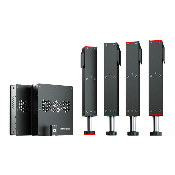
QS-220 2.2.3 QS-220 3DOF SET QS-220 3DoF is a set composed of four actuators and two Power Cabinets. It can be used to set up various motion rigs. For installation details go to section 3.2 on page 21. WARNING Check if the package contains all listed parts. If it is incomplete, please contact the distributor/reseller. -
Page 15: Dimensions
2.3. DIMENSIONS POWER CABINET’S MOUNTING HOLE DIMENSIONS The Power Cabinet’s mounting bolts insertion depth: At the bottom: CANNOT exceed 18 mm and CANNOT be less than 13 mm. On the sides: CANNOT exceed 16 mm and CANNOT be less than 12 mm. - Page 16 QS-220 QS-220’S MOUNTING HOLE DIMENSIONS The QS-220’s mounting bolts insertion depth CANNOT exceed 20 mm and CANNOT less than 10 mm.
-
Page 17: Power Requirements
2.4. POWER REQUIREMENTS INFO QS-220 requires a 120/230±10% VAC 50-60 Hz single phase with ground and neu- tral connection (for grounding details go to section 2.6 on page 18). Power Cabinet contains the power supply for connected actuators. If there is no cer- tainty if fuses or entire electrical installation can handle QS-220’s power requirements, contact a qualified electrician. -
Page 18: Power Consumption
QS-220 2.5. POWER CONSUMPTION Tables below contain power consumption data for QS-220 3DoF setup: 230V ±10% 50-60Hz PERFOR- HEAVY DUTY Q-MODE Single phase MANCE Average power consumption - stress test [W] Average power consumption - typical game [W] Peak power for converter specification [kVA] Peak current for breaker specification [A]... -
Page 19: Environmental Conditions
WARNING The power supply for QS-220 includes an electric cord with an equipment- grounding conductor and a grounding plug. The plug must be plugged into a matching socket that is correctly installed and grounded in accordance with ap- propriate local codes and ordinances. It is recommended to use multiple, sepa- rately fused wall sockets. -
Page 20: Setup And Installation
QS-220 SETUP AND INSTALLATION 3.1. BEFORE INSTALLATION Qubic System DOES NOT approve exceeding or ignoring any of the points below and responsible for malfunctions, failures or injuries that are results of these actions. WARNING Dangerous voltage level may occur in the Power Cabinet and con- nected cables during the operation and up for a few minutes after turning off the machine. -
Page 21: Connecting Qs-220 To A Cockpit
3.2. CONNECTING QS-220 TO A COCKPIT Actuators MUST BE connected with the mounting brackets with 8 bolts (M8x20) each. Mounting brackets MUST BE connected with user’s cockpit with 4 bolts (M8x16) each. Power Cabinet has to be mounted to cockpit using at least 4 bolts (M6x16) – we recommend mounting it in the middle of the motion rig. - Page 22 QS-220 INFO QS-220 adapter brackets for actuators are sold separately. To connect the QS-220 actuator to the aluminium based profile cockpit, following hardware is provided: Part description Qty. Mounting bracket (2 pieces) Bolt M8 x 16 (DIN 912) T-Slot (profile 8) nut M8 Bolt M8x16 (ISO 7380-1) WARNING All included bolts...
- Page 23 To connect the Power Cabinet to the aluminium based profile cockpit, following hardware is provided: Part description Qty. Adapter plate Bolt M6x16 (DIN 7991) T-Slot (Profile 8) nut M6 Bolt M6x16 (ISO 7380-1) Illustrations of Power Cabinet mounting to an aluminium based profile (profile 8) cockpit (space between two profiles must be 210 mm):...
- Page 24 QS-220 Mounting variant no. 2 There is an alternative way of mounting the QS-220’s Power Cabinet. Use the outer holes in the adapter plates to mount the Power Cabinet to a profile that is further away (272 mm between the two profiles). INFO You can mount the Power Cabinet differently to fit your cockpit using bot- tom or side mounting holes.
-
Page 25: Qs-220 2Dof Layouts
3.3. QS-220 2DOF LAYOUTS Number of the actuator is defined by the CFG DIP switch on the Power Cabinet. For more information go to 3.4 on page 26. -
Page 26: Qs-220 2Dof Cfg Dip Switch Configuration
QS-220 3.4. QS-220 2DOF CFG DIP SWITCH CONFIGURATION The CFG DIP switch MUST BE set to an appropriate position. It specifies the actuator pair number (1-2, 3-4, 5-6, etc.). Refer to layouts (section 3.3 on page 25) for 2DoF actuator numbers in a specific settings and set the CFG DIP switches accordingly. -
Page 27: Qs-220 2Dof Cable Connections
3.5. QS-220 2DOF CABLE CONNECTIONS To connect the QS-220 2DoF variant proceed with following steps and connect the cables according to the connections diagram: INFO In the QS-220 2DoF set both the CFG DIP switches in the UP position. - Page 28 QS-220 INFO The order of connecting the cables to Power Cabinet is not important. But ensure keeping the CFG DIP switches set according to appropriate layout. Check section 3.4 on page 26 for layout setup information. Set the correct position of the CFG DIP switch according to the actuators layout of your choice (more information about QS-220 2DoF CFG Switch po- sition and layout selection in section 3.4 on page 26).
-
Page 29: Qs-220 3Dof Layouts
3.6. QS-220 3DOF LAYOUTS Number of the actuator is defined by the CFG DIP switch on the Power Cabinet. For more information go to 3.7 on page 31. - Page 30 QS-220...
-
Page 31: Qs-220 3Dof Cfg Dip Switch Configuration
3.7. QS-220 3DOF CFG DIP SWITCH CONFIGURATION The CFG DIP switch MUST BE set to an appropriate position. It specifies the actuator pair number (1-2, 3-4, 5-6, etc.). Refer to layouts (section 3.6 on page 29) for actuator numbers in a specific settings and set the CFG DIP switches accordingly. -
Page 32: Qs-220 3Dof Cable Connections
QS-220 3.8. QS-220 3DOF CABLE CONNECTIONS To connect the QS-220 3DoF variant proceed with following steps and connect the cables according to the connections diagram: INFO Motion Lock can be plugged into any Power Cabinet in the circuit but in or- der to create a working safety-stop system - Power Cabinets in circuit must be connected together with Motion Lock interlink cables (for Motion... - Page 33 Set the correct position of the CFG DIP switches according to the actuators layout of your choice (more information about QS-220 3DoF CFG DIP switch position and layout selection in section 3.7 on page 31). Plug in the Motion Lock Switch into the "ML UP" port in the first Power Cabinet.
-
Page 34: Qs-220 With Qs-Ch2 Cable Connections
QS-220 3.9. QS-220 WITH QS-CH2 CABLE CONNECTIONS Example of QS-220 3DoF connecting with a traction loss system (QS-CH2). - Page 35 Set the correct position of the CFG DIP switches according to the actuators layout of your choice (more information about QS-220 3DoF CFG DIP switch position and layout selection in section 3.7 on page 31). Set the correct position of the QS-CH2 CFG DIP switch, according to a dia- gram from a previous page.
-
Page 36: Qs-220 With Qs-Ch2, Qs-Bt1 And Qs-Dd-20 Motion Lock Diagrams
QS-220 3.10. QS-220 WITH QS-CH2, QS-BT1 AND QS-DD-20 MOTION LOCK DIAGRAMS Neither QS-DD-20 nor QS-BT1 need a M-BUS connection with any Power Cabinet. They communicate via USB cable directly with the PC. INFO For more information on cable connections with other Qubic System de- vices go to QS-BT1 User Manual (section 5.6. - Page 37 Variant #2 QS-220 3DoF with a seat belt tensioner (QS-BT1) and a direct drive steering wheel (QS-DD-20). QS-220 3DoF with a motion platform (QS-CH2), seat belt tensioner (QS-BT1) and a direct drive steering wheel (QS-DD-20).
- Page 38 QS-220 QS-220 3DoF with a motion platform (QS-CH2) and seat belt tensioner (QS- BT1). QS-220 2DoF with a seat belt tensioner (QS-BT1).
-
Page 39: Software Installation
3.11. SOFTWARE INSTALLATION The SERIAL NUMBER can be found on the M10 identification label in the XXXXXX- XXXXXX-XXXXX-XXXXXX format. This serial number is also used for activation of FSMI (ForceSeatMI) and MT (Motion Theater) licenses - check information in section 3.11 on page 46. Software installation procedure: Connect the devices according to the cables connection diagram - see sec- tion 3.5 for QS-220 2DoF (p. - Page 40 QS-220 Check position of the Motion Lock Switch - unpress if needed (go to sub- section 5 on page 48 for a reference illustration). The QS-220 will perform a start-up calibration - DO NOT change the payload of the QS-220 until the procedure is over. If QubicManager has recognized the QS-220 correctly, the status of the ma- chine visible in the lower left corner will change to Connected.
- Page 41 Go to Tools and Diagnostics Devices and select Configure. For QS-220 2DoF set: Choose the correct layout variant from the list (2 ac- tuators setup).
- Page 42 QS-220 For QS-220 3DoF set: Choose the correct layout variant from the list (4 ac- tuators setup). For QS-220 3DoF set with traction loss control (QS-CH2): Choose the correct layout variant from the list (4A+T setup).
- Page 43 Measure the width between front side actuators. Enter the value in the platform dimensions Width field (in millimeters). Measure the length between front and rear side actuators. Enter the value in the platform dimensions Length field (in millimeters). Scroll down and choose one of the operation modes: INFO Q-MODE is unavailable for QS-220 in 120 VAC environment.
- Page 44 QS-220 Close the configuration and return to the main application window. Choose the game and check profile details by clicking on the game tile. Adjust the motion effects intensity up to your preferences in the game pro- file window. Scroll down to see all of the settings.
- Page 45 Activate a profile by clicking the Activate button. Launch the game by clicking the Run the game button. You can also adjust the settings during the game simulation by pressing ALT+TAB and switching between the applications - once the profile is active changes will apply instantly.
- Page 46 QS-220 INFO If you need the serial number to activate other software licenses such as ForceSeatMI or ForceSeatDI, it can be found in the QubicManager. Af- ter connecting the QS-220 go to Tools and Diagnostics Devices. Serial number is visible under the device name: WARNING The software is provided "as is", without warranty of any kind, express or implied, including but not limited to the warranties of merchantability,...
-
Page 47: Maintenance And Cleaning
WARNING To minimize the risk of QS-220’s actuator failure, check the condition of the linear actuator’s rubber seals once a month. Lubricate them externally, if necessary, using silicon grease. Manufacturer tested silicon grease specifications: Working conditions (°C): -40 do +200... -
Page 48: Troubleshooting
QS-220 TROUBLESHOOTING WARNING DO NOT attempt to do any repairs by yourself. It is dangerous and voids the warranty! Repairs should be consulted with technical support and then performed by a qualified technician. Before contacting technical support, try this: Check Action Center in QubicManager. Check all cable connections in the device. -
Page 49: Creating A Snapshot
5.1. CREATING A SNAPSHOT A snapshot is the easiest and fastest way to diagnose a problem. If you send in the zip file generated in the snapshot menu along with a description of the problem, technical support receives the necessary information about the prod- uct and its configuration. - Page 50 QS-220 Select data that will be included in the snapshot. Scroll down, consent to the technical support terms and conditions and select Create & Show: The snapshot has been created, click the OK button - the folder with the snapshot ZIP file will open. Attach the snapshot ZIP file to your support request.
-
Page 51: Discord Channel
5.2. DISCORD CHANNEL We strongly recommend joining our discord channel, where our growing com- munity is sharing amazing tips and ideas of how to set up, use and tune the Qubic System products. You can also send questions for technical support or get answers directly from the community. -
Page 52: Advanced Applications
QS-220 ADVANCED APPLICATIONS INFO Examples shown in this section describes optional application of external safety and power cut-off devices. If you wish to expand the functionality of your motion system, read the whole section to have a good understand- ing of how to apply and what functionality to expect. Apply at your own discretion. - Page 53 Example application of single-channel safety relay that controls ML and additional devices : Example wiring diagram of application of one-channel safety relay with E-STOP button:...
-
Page 54: Implementing The Working Zone Protection
QS-220 6.2. IMPLEMENTING THE WORKING ZONE PROTECTION For protection against accidental hit from moving parts of the platform, safety gate with opening sensor* can be connected to safety relay input for activating ML function. When the gate is opened, the safety relay output activates the ML (Motion Lock) function and stops the motions of the platform. -
Page 55: Increasing Safety Level
6.3. INCREASING SAFETY LEVEL WARNING Modifications of the safety system, involving application of the power line contactors, shall be performed only by a competent person. A competent person is a qualified and knowledgeable person, who because of their training, experience has the knowledge required to apply those changes. It is user responsibility to commission modification of the safety system to a competent person, experienced with industrial wiring practices, which will be required to undertake the installation. -
Page 56: Adding Power-Cut Circuit With E-Stop Button
QS-220 6.3.2 ADDING POWER-CUT CIRCUIT WITH E-STOP BUTTON If specific SIL/PL rated level needs to be achieved, it might be necessary to in- stall a power cut-off device. Two contactors connected in series and controlled by safety relay can be used to provide or cut-off power line to QS-SB2 power cabinets. - Page 57 Example wiring diagram of application of power line contactors and one-channel safety relay with E-STOP INFO PE (protective grounding/earthing) connection is omitted for better trans- parency...
-
Page 58: Implementing The Working Zone Protection With Power-Cut Circuit
QS-220 6.3.3 IMPLEMENTING THE WORKING ZONE PROTECTION WITH POWER-CUT CIRCUIT In example application contactors connected in series provide power line to the QS-SB2 power cabinets. When safety function on safety relay input is triggered, a safety relay will switch off the power contactors, thus cutting-off the power to the platform. -
Page 59: Environmental Impact And Disposal
ENVIRONMENTAL IMPACT AND DISPOSAL DO NOT dispose this product with standard household waste, leave it at the nearest collection point for the disposal of electrical and electronic equipment. QS-220 is an advanced device and if stored or disposed of incorrectly, it could harm the environment or/and other people. -
Page 60: Warranty
QS-220 WARRANTY Motion Systems warrants to the consumer that this product shall be free from defects in materials and workmanship, for a warranty period which corresponds to the time limit to bring an action for concerning this product. For commercial customers, there is a one (1) year limited warranty, starting on the original date of purchase. -
Page 61: Copyright
COPYRIGHT Qubic System is a trademark of Motion Systems. All rights reserved. All the contents in this user manual are the intellectual property of Motion Sys- tems. No part of this manual, including the products and software described in it, shall be modified or translated into any language without the prior written permission of Motion Systems.
Need help?
Do you have a question about the QS220 and is the answer not in the manual?
Questions and answers