Table of Contents
Advertisement
Quick Links
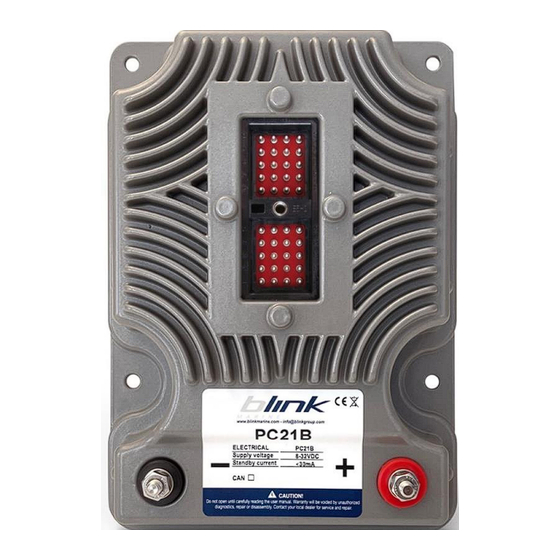
PC21B CAN J1939 Slave
Features:
CAN2.0B supported
12V or 24V power supply supported
Electronic overcurrent protection and automotive mini blade fuse
22 switched circuits
Up to 4 low side outputs
Operating temperature range: -20 to +85°C
Splash proof (IP65)
Deutsch DRC10-40P-A-004 40pin connector
1/36
PC21B_J1939SlaveUM_REV1.1
Advertisement
Table of Contents

Subscribe to Our Youtube Channel
Related Manuals for Blink Marine PC21B


Summary of Contents for Blink Marine PC21B
-
Page 1: Features
PC21B CAN J1939 Slave Features: CAN2.0B supported 12V or 24V power supply supported Electronic overcurrent protection and automotive mini blade fuse 22 switched circuits Up to 4 low side outputs Operating temperature range: -20 to +85°C Splash proof (IP65) Deutsch DRC10-40P-A-004 40pin connector 1/36 PC21B_J1939SlaveUM_REV1.1... -
Page 2: Table Of Contents
Contents Features: ........................................1 How to Connect CAN bus: .................................3 PC21B Technical Specifications ..............................3 Mechanical Features .................................4 Connector 40 pin: ..................................5 Electrical Loads Connection ..............................6 Pin Assignment ..................................7 Output State Machine Diagram ..............................8 Message header description ..............................10 General Data Format ................................10 Default Settings ..................................11... -
Page 3: How To Connect Can Bus
You may need to place a 120Ω terminating resistor between CAN-L and CAN-H. NOTE: for some hardware versions the PC21B PCB is equipped with a built-in terminating resistor which can be enabled via software. See command 78h for further details. -
Page 4: Mechanical Features
Housing: aluminium AB46100 anodic oxidation + powder-coating + zinc-coated bronze ZnCu20 • Seal: EPDM GASKET • Power studs: Blink Marine CuZn20 UNC#14-20 Mechanical dimensions Dimensions are in millimeters. Warning: to avoid breakage do not tighten the nuts of battery terminals with a torque exceeding 3.5 Nm! PC21B_J1939SlaveUM_REV1.1 4/36 www.blinkmarine.com... -
Page 5: Connector 40 Pin
4. Connector 40 pin: The 40-pin automotive connector DRC10-40P-A004 mates with housing for female terminals DRC16-40SA. Output Ch10 Ch11 TXRX+ CANL TXRX+ Ch16 Ch16 Ch20 Ch21 CANH TXRX- TXRX- Ch30 Ch31 Ch32 Ch33 Ch37 Ch38 Ch39 Ch40 PC21B_J1939SlaveUM_REV1.1 5/36 www.blinkmarine.com... -
Page 6: Electrical Loads Connection
5. Electrical Loads Connection HIGH side switch: The electrical device is connected between an output pin of the PowerCore and ground. The output pin state can be HIGH (pin voltage at a battery voltage) or OFF (pin floating). The ground can be connected either to one of the ground pins of the PowerCore or directly to the battery’s negative pole. -
Page 7: Pin Assignment
6. Pin Assignment Low Side Level Sense Tach Sense Slew Rate Function Rating Driver Input Input output Control O – HB O – HB O – HB O – HB Reserved CANL Reserved 16,17* CANH Reserved Reserved O/TSI O/TSI 37** 38** 39** 40**... -
Page 8: Output State Machine Diagram
Function Summary: • O: Output high side pin triggered by CAN bus commands. • O-HB: Output high side or low side pin triggered by CAN bus commands (Half Bridge pin). • I: Input pin (Digital level sense). • TSI: Input pin (Tachometer sense). •... - Page 9 The output pin can be set to one of the 4 states available: Output state Pin voltage Equivalent Circuit Floating HIGH Battery Voltage Ground Voltage FAULT Floating To avoid cross conduction, the system does not allow to change the state of an output pin from HIGH to LOW and from LOW to HIGH.
-
Page 10: Message Header Description
Parameter Group Number: 61184 (EF00h) used for command type messages; 59904 (EA00h) used for request type messages. An example of CAN identifier of messages sent to the PC21B is 18EF2100h where: 21h is the destination address (PC21B) 00h is the source address. -
Page 11: Default Settings
10. Default Settings Setting Default status or level How to change Baud rate 250kbit/s Command 6Fh Source address Command 70h PC21B identifier Command 70h PX output current threshold Command 0Dh Periodic fault message transmission Disabled Command 71h Fault-event message transmission Enabled... -
Page 12: Set Single Pin State (01H)
11. Set single pin state (01h) This message is sent to the PowerCore to set the state of one single output pin. Byte 0 Header bytes Byte 1 Byte 2 Set single pin state XX: pin number 01h: P1 02h: P2 03h: P3 04h: P4 05h: P5... -
Page 13: Set Multiple Pin State (02H)
12. Set multiple pin state (02h) This message is sent to the PowerCore to set the state HIGH, LOW or OFF of more output pins at the same time. Byte 0 Header bytes Byte 1 Byte 2 Set multiple pin state XXh: state 00h: OFF Byte 3... -
Page 14: Set Pwm State (03H)
13. Set PWM state (03h) This command enables the PWM state on the outputs (PIN 6, PIN 10 and PIN 31) supporting this feature. NOTE: if this feature is enabled when the outputs are already HIGH, the previous command is overwritten. -
Page 15: Fault-Event Message (01H)
0Fh: P30 10h: P31 11h: P32 12h: P33 13h: P37 14h: P38 15h: P39 16h: P40 Byte 4 Fault condition detected Byte 5 PC21B identifier Byte 6,7 Not used Examples: Direction Identifier Format Message Data From PowerCore 18EFFF21h 04 1B 01 01 01 21 FF FF... -
Page 16: Configuration Commands
Configuration commands In this section it is shown a list of control messages to configure the PowerCore and/or modify default settings. Where applicable, changes take effect immediately and are stored in non-volatile memory address unless otherwise noted. Note: the request-type messages have 3-bytes data length. (See ISO 11783-3 for further details) Note 2: for some commands the set values are kept at the startup. -
Page 17: Read Fault Event (0Bh)
16. Read Fault event (0Bh) The following message sent to the PowerCore allows to read which output pins have gone into the fault condition. Identifier 18EA2100h Byte 0 Read Fault event Byte 1 Single frame Byte 2 Enable reading Answer: Identifier 18EAFF21h Byte 0... -
Page 18: Read Powercore Electronic Values (0Ch)
17. Read PowerCore electronic values (0Ch) The following message sent to the PowerCore allows to read the analog values of the output currents, the total current and the battery voltage. Identifier 18EA2100h Byte 0 Read PowerCore electronic values Byte 1 single frame XXh: pin number 01h: P1... -
Page 19: A) Set Output Current Threshold (0Dh)
18. a) Set Output current threshold (0Dh) This command sets for each output pin the current threshold. Refer to the pin assignment table to check the maximum currents of each pin. The default threshold is 10A. NOTE: the maximum current of each pin is 15A. NOTE 2: If it is set a value too high, the threshold is set at the maximum value supported for the selected pin. -
Page 20: B) Read Output Current Threshold (0Dh)
b) Read Output current threshold (0Dh) The following message sent to the device allows to require the output current threshold value set for the selected pin. Identifier 18EA2100h Byte 0 Read output current threshold Byte 1 single frame Byte 2 Pin number Answer: Identifier... -
Page 21: A) Protection Trip Delay (0Eh)
19. a) Protection trip delay (0Eh) This message is used to set the protection trip delay for each output. It is possible to select a value between 100ms and 900ms. The default value is 100ms. Byte 0 Header bytes Byte 1 Byte 2 Protection trip delay 01h: P1... -
Page 22: B) Read Protection Trip Delay (0Eh)
b) Read Protection trip delay (0Eh) The following message sent to the device allows to require the protection trip delay value set for the selected pin. Identifier 18EA2100h Byte 0 Read Protection trip delay Byte 1 single frame Byte 2 Pin number Answer: Identifier... -
Page 23: A) Set Tachometer Counter (10H)
20. a) Set Tachometer counter (10h) This message is used to set the start value of the tachometer counter available for PINs 32 and 33. The default counter value is 0000h. Byte 0 Header bytes Byte 1 Byte 2 Set Tachometer counter 01h: PIN 32 Byte 3 02h: PIN 33... -
Page 24: B) Read Tachometer Counter Value (10H)
b) Read Tachometer counter value (10h) The following message sent to the device allows to read the current tachometer counter value for PINs 32 and 33. Identifier 18EA2100h Byte 0 Read Tachometer counter value Byte 1 single frame PIN number Byte 2 01h: PIN 32 02h: PIN 33... -
Page 25: A) Slew Rate Control (11H)
21. a) Slew rate control (11h) When a PIN is configured as output, this command allows to enable or disable the slew rate control. When enabled, the slew control limits the rate at which an output rises from 0 to high voltage level in order to reduce current spikes and EMC emissions. -
Page 26: B) Read Slew Rate Control (11H)
b) Read Slew rate control (11h) The following message sent to the device allows to require which output pins have been set for the slew rate control. Identifier 18EA2100h Byte 0 Read Slew rate control Byte 1 single frame Byte 2 Pin number Answer: Identifier... -
Page 27: A) Normal On Mode (12H)
22. a) Normal ON mode (12h) This command allows configuring the outputs’ state in order to be already active (normal ON mode) when the PowerCore is powered on. The setting is kept at the power on. Byte 0 Header bytes Byte 1 Byte 2 Normal ON mode... -
Page 28: B) Read Normal On Mode (12H)
b) Read Normal ON mode (12h) The following message sent to the device allows to require which output pins have been set for the normal ON mode. Identifier 18EA2100h Byte 0 Read Normal ON mode Byte 1 single frame Byte 2 Pin number Answer: Identifier... -
Page 29: Get Software Revision (2Ah)
23. Get software revision (2Ah) Identifier 18EA2100h Byte 0 Get software revision Byte 1 single frame Byte 2 Enable reading Answer: Identifier 18EAFF21h Byte 0 Command byte Byte 1 Single frame 06h: command understood Byte 2 15h: command not accepted Byte 3 Byte 4 SW revision ASCII... -
Page 30: Baud Rate Setting (6Fh)
Either or both the Source Address or PowerCore identifier may be changed independently. Connecting only one PC21B to the bus during the address change is recommended. If an invalid value is chosen, then no change is done to the stored value. -
Page 31: Periodic Fault Message Transmission (71H)
This command enables or disables the periodic transmission of the fault-event message. When enabled, a message informing if the PIN has entered fault condition is periodically sent for each output of the PC21B. The period is set to 1s as default value but can be changed by command 77h (see chapter 29 for further details). -
Page 32: Fault-Event Message Transmission (72H)
27. Fault-event message transmission (72h) This command enables or disables the transmission of the fault-event message (see chapter for further details). This feature is active by default, but if it is disabled when a PIN enters fault condition the PowerCore will not transmit the related message. Byte 0 Header bytes Byte 1... -
Page 33: Heartbeat (75H)
28. Heartbeat (75h) This message enables or disables the transmission of Heartbeat message. This message is designed to indicate to other devices on the bus that this unit continues to work. Byte 0 Header bytes Byte 1 Byte 2 Heartbeat Byte 3 00h Disabled (default) 01h Enabled... -
Page 34: Periodic Fault Message Period (77H)
29. Periodic fault message period (77h) This message sets the period time for the periodic fault-event message transmission (see chapter 26 for further details). This does not enable or disable the messages. Byte 0 Header bytes Byte 1 Byte 2 Periodic fault event message period XX: Period in milliseconds ÷... -
Page 35: Set Can Protocol
Set CAN protocol This set of messages are used to change to the desired CANbus protocol. • Change from CANopen to J1939: Direction Identifier Format Message Data 600h + current CAN ID To PowerCore 2F FF 20 00 01 Change to J1939 (default 60Ch) •... -
Page 36: Revision History
33. Revision history Manual Date Comment Revision 05/04/2023 First release Second release: - Added note on chapters 5-6 05/09/2023 - Added sub-index 02h to the Tachometer counter command on chapter 20 PC21B_J1939SlaveUM_REV1.1 36/36 www.blinkmarine.com...
Need help?
Do you have a question about the PC21B and is the answer not in the manual?
Questions and answers