Table of Contents
Advertisement
Quick Links
THE PRESENT MANUAL IS FOR REFERENCE ONLY AND MIGHT BE NOT UP TO DATE TO THE LATEST
VERSION.PLEASE CONTACT US FOR GETTING THE MOST UPDATED FILE
Via Montefeltro, 6 – 20156 Milano (MI) – Italy
Tel. +39 (02) 3088583 – Fax +39 (02) 33406697
www.blinkmarine.com
–
info@blinkgroup.com
PC10
CANOPEN SLAVE
Features
CANopen BUS
12V and 24V power supply supported
Electronic protection from short circuit
4 bypass circuits for emergency
Up to 12 power outputs with current sense
3 high current outputs
Up to 8 digital inputs
Up to 8 analog inputs
Up to 4 low side outputs
Operating temperature range: -20 to +85°C
Splash proof (IP65)
Molex connectors MX150L series
- 1 -
FOR REFERENCE ONLY
Advertisement
Table of Contents

Related Manuals for Blink Marine PC10


Summary of Contents for Blink Marine PC10
- Page 1 PC10 CANOPEN SLAVE Features CANopen BUS 12V and 24V power supply supported Electronic protection from short circuit 4 bypass circuits for emergency Up to 12 power outputs with current sense 3 high current outputs Up to 8 digital inputs Up to 8 analog inputs Up to 4 low side outputs Operating temperature range: -20 to +85°C...
-
Page 2: Table Of Contents
Table of contents How to Connect CAN bus: ............................4 PC10 Technical Specifications ..........................4 Mechanical Features ..............................5 Electrical Loads Connection ............................ 6 Bypasses ..................................6 Pin Assignment ................................7 Hardware Block Diagram ............................8 Output State Machine Diagram ..........................8 CANopen Messages Structure ........................... - Page 3 Object 1017h: Producer Heartbeat Time ...................... 25 Object 1000h: Device Type ........................... 25 Object 1400h: Receive PDO 0 Communication Parameter ..............26 Object 1401h: Receive PDO 1 Communication Parameter ..............26 Object 1600h: Receive PDO 0 Mapping Parameter .................. 27 Object 1601h: Receive PDO 1 Mapping Parameter ..................
-
Page 4: How To Connect Can Bus
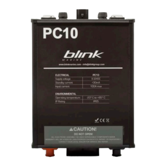
Each end of the CAN bus is terminated with 120Ω resistors in compliance with the standard to minimize signal reflections on the bus. You may need to place a 120Ω resistor between CAN-L and CAN-H. 2. PC10 Technical Specifications Electrical Value... -
Page 5: Mechanical Features
Mechanical Features Extruded aluminum housing • End-panel power and I/O connections 2 x 5,7mm power lugs Amphenol SurLok Plus with • sealed plug. 16 pin Molex MX150L connectors (Molex part # 19427-0049). Mates with 16 pin receptacle • (Molex part # 19418-0030) using 14-16 gauge contact (Molex part #19420-0009) One 4 pin can bus connector Molex MX150L (Molex #19427-0032). -
Page 6: Electrical Loads Connection
4. Electrical Loads Connection HIGH side switch: The electrical device is connected between an output pin of the PowerCore and ground. The output pin state can be HIGH (pin voltage at battery voltage) or OFF (pin floating). The ground can be connected either to one of the ground pins of the PowerCore or directly to the battery’s negative pole. -
Page 7: Pin Assignment
6. Pin Assignment Connector Function Rating High Level Analog Optional Optional Current Side Sense Sense Relay Diode Pass Driver Driver Contact Protectio CAN L CAN H BUS PWR Function Summary O: Output high side pin • I/O: Input / output high side pin •... -
Page 8: Hardware Block Diagram
7. Hardware Block Diagram 8. Output State Machine Diagram FAULT RESET HIGH HIGH HIGH HIGH Via Montefeltro, 6 – 20156 Milano (MI) – Italy - 8 - Tel. +39 (02) 3088583 – Fax +39 (02) 33406697 www.blinkmarine.com – info@blinkgroup.com FOR REFERENCE ONLY... - Page 9 The output pin can be set to one of the 4 states available: Output state Pin voltage Equivalent Circuit Floating HIGH Battery Voltage Ground Voltage FAULT Floating To avoid cross conduction, the system does not allow to change the state of an output pin from HIGH to LOW and from LOW to HIGH.
-
Page 10: Canopen Messages Structure
9. CANopen Messages Structure All the data type used are unsigned integer and the syntax is specified in the following table: NMT MESSAGES The Network Management messages follow a master-slave structure. Through NMT services, CANopen devices are initialized, started, reset, or stopped. All CANopen devices are regarded as NMT slaves. -
Page 11: Can Messages For Managing Output Pins
10. CAN Messages for Managing Output Pins Output state Direction Can message Write PDO 300h + node-ID HIGH Read/Write SDO Object 2001h Read/Write SDO Object 2008h sub-index 02h Read/Write SDO Object 2001h Read/Write SDO Object 2008h sub-index 03h Write PDO 200h + node-ID Read/Write SDO Object 2001h Read/Write... -
Page 12: Nmt Messages
NMT MESSAGES The Network Management Messages follow a master-slave structure. Through NMT services, CANopen devices are initialized, started, reset, or stopped. All CANopen devices are regarded as NMT slaves. NMT messages have CAN-ID always equal to 00h. 12. Start CANopen Node Identifier Byte 0 Start CANopen node... -
Page 13: Stop Canopen Node
15. Stop CANopen Node Identifier 00h Byte 0 02h: Stop CANopen node 00h: Stop CANopen node (old SW compatibility) Byte 1 PowerCore CAN ID 00h: Stop all the devices 15h: Stop the PowerCore with CAN ID = 15h. Byte 2, Not used Example: Direction... -
Page 14: Pdo Messages
PDO Messages 18. Set Output HIGH Identifier 300h + current CAN ID Default 315h Byte 0 J1-8 J1-7 J1-6 J1-5 J1-4 J1-3 J1- ‘1’= set HIGH J1-1 ‘0’= do nothing Byte 1 J1-11 J1-10 J3-4 J1- ‘1’= set HIGH 16 J1-9 ‘0’= do nothing Byte 2,7 Not used... -
Page 15: Sdo Messages
SDO messages 21. Object 2001h: Single Pin State This object sets and reads the state of each output pins. Identifier 600h + current CAN ID Default 615h Byte 0 Read Device Register Write 1-byte data Byte 1 CAN Object 2001h Byte 2 Byte 3 Highest sub-index supported (read only) -
Page 16: Object 2002H: Output Current Threshold
22. Object 2002h: Output Current Threshold This object sets and reads for each output pins the current thresholds. Refer to the pin assignment table to check the maximum currents of each pin. If you set a too high value a response error occurs, and the value is set to the maximum. -
Page 17: Object 2003H: Read Digital Input 8-Bit
23. Object 2003h: Read Digital Input 8-bit This object reads digital input values. The digital input is applicable only on some pins (refer to the pin assignment table). The unsupported pins have always the value ‘0’. Identifier 600h + current CAN ID Default 615h Byte 0 Read Device Register... -
Page 18: Object 2004H: Read Analog Input
24. Object 2004h: Read Analog Input This object reads analog input values with 8-bit resolution. 14V=FFh. Expected value: (Vin · 255/14) Note: this feature requires the installation of an additional component on the PowerCore. Identifier 600h + current CAN ID Default 615h Byte 0 Read Device Register... -
Page 19: Object 2007H: Read Powercore Electronic Values
25. Object 2007h: Read PowerCore Electronic Values This object reads the analog values of the output currents, the total current and the battery voltage. Identifier 600h + current CAN ID Default 615h Byte 0 Read Device Register Byte 1 CAN Object 2007h Byte 2 Byte 3 Highest sub-index supported (read... - Page 20 Identifier 600h + current CAN ID Default 615h Byte 0 Read Device Register Write 4-bytes Byte 1 CAN Object 2008h Byte 2 Byte 3 Highest sub-index supported (read only) Output OFF Output HIGH Output LOW Output PWM (on supported pins) Output FAULT (read only) Output RESET (write only) Byte 4...
-
Page 21: Object 2010H: Baud Rate Settings
To PowerCore 23 08 20 04 18 00 Set PWM on J1-4 and 04 00 J1-5 with D=40% PowerCore 60 08 20 04 00 00 reply 00 00 To PowerCore 23 08 20 04 80 00 Set PWM on J1-8 01 00 with D=10% PowerCore... -
Page 22: Object 2011H: Set Node Id
28. Object 2011h: Set node ID This object sets and reads the CANopen node-id. Identifier 600h + current CAN ID Default 615h Read Device Register Byte 0 Write 1-byte data Byte 1 CAN Object 2011h Byte 2 Byte 3 Sub index Byte 4 New node id: (01h –... -
Page 23: Object 2013H: Set Device Active On Startup
30. Object 2013h: Set Device Active on Startup If device is active on startup don’ t need start command from master. Identifier 600h + current CAN ID Default 615h Byte 0 Read Device Register Write 1-byte data Byte 1 CAN Object 2013h Byte 2 Byte 3 Sub index... -
Page 24: Object 2015H: Set Boot-Up Service
32. Object 2015h: Set Boot-up Service This object enables and disables the boot-up message. Identifier 600h + current CAN ID Default 615h Byte 0 Read Device Register Write 1-byte data Byte 1 CAN Object 2015h Byte 2 Byte 3 Sub index Byte 4 00h: NOT ACTIVE 01h: ACTIVE... -
Page 25: Object 1017H: Producer Heartbeat Time
33. Object 1017h: Producer Heartbeat Time The producer heartbeat time shall indicate the configured cycle time of the heartbeat Identifier 600h + current CAN ID Default 615h Byte 0 Read Device Register Set device register Byte 1 CAN Object 1017h Byte 2 Byte 3 Sub index... -
Page 26: Object 1400H: Receive Pdo 0 Communication Parameter
35. Object 1400h: Receive PDO 0 Communication Parameter Describes the RPDO parameters for turning OFF the outputs. Identifier 600h + current CAN ID Default 615h Byte 0 Read Device Register Byte 1 CAN Object 1400h Byte 2 Byte 3 Highest sub-index supported COB-ID used by RPDO Transmission type Byte 4,7... -
Page 27: Object 1600H: Receive Pdo 0 Mapping Parameter
37. Object 1600h: Receive PDO 0 Mapping Parameter Describes the RPDO 0 mapping parameters for turning OFF the outputs. Identifier 600h + current CAN ID Default 615h Byte 0 Read Device Register Byte 1 CAN Object 1600h Byte 2 Byte 3 Highest sub-index supported Application object: Set Output OFF Byte 4,7... -
Page 28: Object 1800H: Transmit Pdo 0 Communication Parameter
39. Object 1800h: Transmit PDO 0 Communication Parameter Describes the TPDO communication parameters for outputs FAULT state. Identifier 600h + current CAN ID Default 615h Byte 0 Read Device Register Byte 1 CAN Object 1800h Byte 2 Byte 3 Highest sub-index supported COB-ID used by TPDO Transmission type Byte 4,7... -
Page 29: Object 1A04H: Transmit Pdo 4 Mapping Parameter
41. Object 1A04h: Transmit PDO 4 Mapping Parameter Describes the TPDO 4 communication parameters for reading output FAULT states. Identifier 600h + current CAN ID Default 615h Byte 0 Read Device Register Byte 1 CAN Object 1A04h Byte 2 Byte 3 Number of mapped objects application object Byte 4,7... -
Page 30: Object 1A05H: Transmit Pdo 5 Mapping Parameter
42. Object 1A05h: Transmit PDO 5 Mapping Parameter Describes the TPDO 5 communication parameters for reading analog inputs. Identifier 600h + current CAN ID Default 615h Byte 0 Read Device Register Byte 1 CAN Object 1A05h Byte 2 Byte 3 Number of mapped objects application object: read analog input J1-1 application object: read analog input J1-2... -
Page 31: Object 1A06H: Transmit Pdo 6 Mapping Parameter
43. Object 1A06h: Transmit PDO 6 Mapping Parameter Describes the TPDO 6 communication parameters for reading output currents J1-1..J1-8 Identifier 600h + current CAN Default 615h Byte 0 Read Device Register Byte 1 CAN Object 1A06h Byte 2 Byte 3 Number of mapped objects application object: read output current J1-1 application object: read output current J1-2... -
Page 32: Object 1A07H: Transmit Pdo 7 Mapping Parameter
44. Object 1A07h: Transmit PDO 7 Mapping Parameter Describes the TPDO 7 communication parameters for reading output currents J1-9..J1- 1, total current and battery voltage. Identifier 600h + current CAN Default 615h Byte 0 Read Device Register Byte 1 CAN Object 1A07h Byte 2 Byte 3 Number of mapped objects... -
Page 33: Revision History
45. Revision history Date Manual Revision Comment Related SW version 27/05/2016 First release 07/09/2018 New release Via Montefeltro, 6 – 20156 Milano (MI) – Italy - 33 - Tel. +39 (02) 3088583 – Fax +39 (02) 33406697 www.blinkmarine.com – info@blinkgroup.com FOR REFERENCE ONLY...
Need help?
Do you have a question about the PC10 and is the answer not in the manual?
Questions and answers