Table of Contents
Advertisement
Quick Links
THE PRESENT MANUAL IS FOR REFERENCE ONLY AND MIGHT BE NOT UP TO DATE TO THE LATEST VERSION.
Via Montefeltro, 6 – 20156 Milano (MI) – Italy
Tel. +39 (02) 3088583 – Fax +39 (02) 33406697
www.blinkmarine.com – info@blinkgroup.com
PKP-1400
CANOPEN USER MANUAL
PLEASE CONTACT US FOR GETTING THE MOST UPDATED FILE
PK-1400_CANOpen_UM_REV1.3
Advertisement
Table of Contents

Related Manuals for Blink Marine PKP-1400


Summary of Contents for Blink Marine PKP-1400
- Page 1 PKP-1400 CANOPEN USER MANUAL THE PRESENT MANUAL IS FOR REFERENCE ONLY AND MIGHT BE NOT UP TO DATE TO THE LATEST VERSION. PLEASE CONTACT US FOR GETTING THE MOST UPDATED FILE Via Montefeltro, 6 – 20156 Milano (MI) – Italy Tel. +39 (02) 3088583 – Fax +39 (02) 33406697 www.blinkmarine.com – info@blinkgroup.com PK-1400_CANOpen_UM_REV1.3...
-
Page 2: Table Of Contents
Table of contents How to connect Deutsch 4 pin: ...................... 4 Reference ............................. 4 Default settings ............................ 5 NMT MESSAGES ........................... 5 Start CANopen node (keypad activation message) ................ 5 Enter pre-operational ........................... 6 Reset CANopen node .......................... 6 Stop CANopen node .......................... 6 Boot-up service ............................. 7 PDO messages ............................ 7 Keys state message .......................... 7 PK-1400 .............................. 7 • Set LED ON message .......................... 8 PK-1400 RED ............................ 8 •... - Page 3 Backlight brightness level ........................ 1 5 Backlight color .......................... 1 5 Set default backlight color ....................... 1 6 Set startup Indicator LEDs brightness level .................. 1 6 Set startup backlight brightness level .................... 1 6 Object 2010h: Baud rate setting ...................... 1 7 Object 2011h: Set Boot-up service ..................... 1 7 Object 2012h: Set device active on startup .................. 1 8 Object 2013h: Set CANopen node ID .................... 1 8 Object 2014h: Set startup LED show .................... 1 9 Object 2015h: LED Power supply ...................... 1 9 Object 2100h: Set DEMO mode .
-
Page 4: How To Connect Deutsch 4 Pin
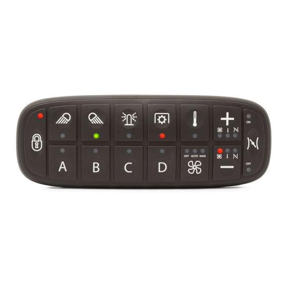
1. How to connect Deutsch 4 pin: PIN COLOUR FUNCTION Blue CAN L White CAN H Black Negative battery Red Vbatt. (12-24V) Each end of the CAN bus is terminated with 120Ω resistors in compliance with the standard to minimize signal reflections on the bus. You may need to place a 120Ω resistor between CAN-L and CAN-H. 2. Reference PowerKey front view. PK-1400 Via Montefeltro, 6 – 20156 Milano (MI) – Italy - 4 - Tel. +39 (02) 3088583 – Fax +39 (02) 33406697 www.blinkmarine.com –... -
Page 5: Default Settings
3. Default settings Setting Default state or level How to change Baud Rate 125 kbit/s Object 2010h CANopen Node ID 15h Object 2013h CANopen Node Stop NMT Message Start CANopen State node Key Brightness 3Fh (Maximum Brightness) Object 2003h Backlight Brightness 00h (OFF) Object 2003h Backlight Color Amber Object 2003h Startup LED Light Complete LED Sequence Object 2014h Show Periodic Message Disable Object 1800h Transmission DEMO mode Disable Object 2100h Heartbeat Message Disable Object 1017h Boot-up service Active Object 2011h... -
Page 6: Enter Pre-Operational
5. Enter pre-operational Identifier 00h Byte 0 80h Enter pre-operational Keypad CAN ID Byte 1 XXh 00h: enter all the keypads 15h: enter the keypad with CAN ID = 15h. Byte 2, 7 00h Not used Example: Direction Identifier Format Message To Keypad Std 80 15 6. Reset CANopen node Identifier 00h Byte 0 81h Reset CANopen node Keypad CAN ID Byte 1 XXh 00h: reset all the keypads 15h: reset the keypad with CAN ID = 15h. Byte 2, 7 00h Not used... -
Page 7: Boot-Up Service
8. Boot-up service This service is used to signal that a NMT slave has entered the NMT state Pre-operational. Identifier 700h + current CAN ID Default 715h Byte 0 00h One data byte is transmitted with value 0. Example: Direction Identifier Format Message From Keypad 715h Std 00h The keypad with CAN ID 15h has entered the NMT state Pre-operational. PDO messages PDO (Process Data Object) are fast telegram messages that can simply manage most important functions. There are no answers for this kind of messages. Each PDO message has an equivalent Service Data Object message. 9. Keys state message The keypad must be activated, see NMT Start CANopen Node message. PK-1400 • Identifier 180 + current CAN ID Default 195h Byte 0 Keys from #1 to #8 Keys: 1=pressed; 0=released K8 K7 K6 K5 – K4 K3 K2 K1 Byte 1 Keys from #9 to #14 Keys: 1=pressed; 0=released 0 0 K14 K13 – K12 K11 K10 K9... -
Page 8: Set Led On Message
10. Set LED ON message The keypad must be activated, see NMT Start CANopen Node message. PK-1400 RED • Identifier 200 + current CAN ID Default 215h Byte 0 R8 R7 R6 R5 – R4 R3 R2 R1 Red LED Byte 1 R16 R15 R14 R13 – R12 R11 R10 R9 Red LED Byte 2 R24 R23 R22 R21 – R20 R19 R18 R17 Red LED Byte 3 R32 R31 R30 R29 – R28 R27 R26 R25 Red LED Byte 4 R40 R39 R38 R37 – R36 R35 R34 R33 Red LED Byte 5, 7 00h Not used Examples: Direction Identifier Format Message LED To Keypad 215 Std 00 00 00 00 00 00 00 00 Turn off all the LED To Keypad 215... -
Page 9: Indicator Leds Brightness Level
Indicator LEDs brightness level The keypad must be activated, see NMT Start CANopen Node message. Identifier 400 + current CAN ID Default 415h Byte 0 XXh Intensity 00h-3Fhà min-100% Byte 1, 7 00h Not used Examples: Direction Identifier Format Message LED To Keypad 415 Std 08 00 00 00 00 00 00 00 Brightness = 12,5% To Keypad 415 Std 10 00 00 00 00 00 00 00 Brightness =25% 12. Backlight brightness level The keypad must be activated, see NMT Start CANopen Node message. Identifier 500 + current CAN ID Default 515h Byte 0 XXh Intensity 00h-3Fhà 0-100% Byte 1, 7 00h Not used... -
Page 10: Sdo Messages
SDO Messages: A SDO (Service Data Object) is providing direct access to object entries of a CANopen device's object dictionary. 13. Object 2000h: Digital input module, keys states This module contains all the Switch State information. A one indicates the switch is on, a zero indicates the switch is off. The keypad must be enabled, see NMT messages. The switch state is reported in the Keypad reply message from byte 4 to byte 5. The mapping is the same of the PDO Key state message. • PK-1400 Identifier 600h + current CAN ID Default 615h Byte 0 40h Read Device Register Byte 1 00h CAN Object 2000h Byte 2 20h Byte 3 01h Sub index Byte 4,7 00h Not used Examples: Direction Identifier Format Message Data To Keypad 615... -
Page 11: Object 2001H: Digital Output Module
14. Object 2001h: Digital output module. This module sets and reads the LED Outputs States. A one indicates the LED is on, a zero indicates the LED is off. a) Set LED ON • PK-1400 LED From L1 to L32 Identifier 600h + current CAN ID Default 615h Byte 0 23h Set Device Register Byte 1 01h CAN Object 2001h Byte 2 20h Byte 3 XXh XX: Sub index 01h: Red LED from L1 to L32 02h: Green LED from L1 to L32 Byte 4 XXh L8 L7 L6 L5 – L4 L3 L2 L1 Byte 5 XXh L16 L15 L14 L13 – L12 L11 L10 L9 Byte 6 XXh... -
Page 12: B) Read Led
b) Read LED ON The LEDs have the same mapping of Set LED ON message • PK-1400 Identifier 600h + current CAN ID Default 615h Byte 0 40h Read Device Register Byte 1 01h CAN Object 2001h Byte 2 20h Byte 3 XXh XX: Sub index 01h: Red LED from L1 to L32 02h: Green LED from L1 to L32 04h: Red LED from L33 to L40 05h: Green LED from L33 to L40 Byte 4,7 00h Not used Examples: Direction Identifier Format Message Data To Keypad 615 Std 40 01 20 01 00 00 00 00 Read red LED from #1 to #32 Keypad reply 595 Std 43 01 20 01 FF FF FF FF... -
Page 13: Object 2002H: Digital Output Module
15. Object 2002h: Digital output module. This module sets and reads the LED Blink States. Each bit position represents the corresponding LED. A one indicates the LED is blinking, a zero indicates the LED is normal. If the blink message is sent when the LED is already ON, the LED blinks in alternate mode. a) Set LED blink • PK-1400 LED From L1 to L32 Identifier 600h + current CAN ID Default 615h Byte 0 23h Set Device Register Byte 1 02h CAN Object 2002h Byte 2 20h Byte 3 XXh XX: Sub index 01h: Red LED blink from L1 to L32 02h: Green LED blink from L1 to L32 Byte 4 XXh L8 L7 L6 L5 – L4 L3 L2 L1 Byte 5 XXh L16 L15 L14 L13 – L12 L11 L10 L9... -
Page 14: B) Read Led Blink
b) Read LED blink The LEDs have the same mapping of Set LED ON message • PK-1400 Identifier 600h + current CAN ID Default 615h Byte 0 40h Set Device Register Byte 1 02h CAN Object 2002h Byte 2 20h Byte 3 XXh XX: Sub index 01h: Red LED from L1 to L32 02h: Green LED from L1 to L32 04h: Red LED from L33 to L40 05h: Green LED from L33 to L40 Byte 4,7 00h Not used Examples: Direction Identifier Format Message Data To Keypad 615 Std 40 02 20 01 00 00 00 00 Read red LED blinking from #1 to #32 Keypad 595 Std... -
Page 15: Object 2003: Brightness Level
16. Object 2003: Brightness Level a) Set Indicator LEDs brightness level Identifier 615h (600h + current CAN ID) Byte 0 2Fh Set Device Register Byte 1 03h CAN Object 2003h Byte 2 20h Byte 3 01h Sub index Byte 4 XXh Intensity 00h-3Fhà min-100% Byte 5,7 00h Not used Example: Direction Identifier Format Message Data To Keypad 615 Std 2F 03 20 01 10 00 00 00 LED brightness = 25% Keypad reply 595... -
Page 16: D) Set Default Backlight Color
d) Set default backlight color Identifier 615h (600h + current CAN ID) Byte 0 2Fh Set Device Register Byte 1 03h CAN Object 2003h Byte 2 20h Byte 3 04h Sub index Byte 4 XXh Backlight Color 01h: red 06h: violet 02h: green 07h: white/light 03h: blue blue 04h: yellow 08h: 05h: cyan amber/orange 09h: yellow/green Byte 5,7 00h Not used Example: Direction Identifier Format Message Data To Keypad... -
Page 17: Object 2010H: Baud Rate Setting
17. Object 2010h: Baud rate setting Identifier 615h (600h + current CAN ID) Byte 0 2Fh Set Device Register Byte 1 10h CAN Object 2010h Byte 2 20h Byte 3 00h Sub index Byte 4 XXh Baud rate 00h: 1000k 01h: Reserved (force to 125k) 02h: 500k 03h: 250K 04h: 125k (Default) 05h: Reserved (force to 125k) 06h: 50k 07h: 20k Byte 5,7 00h Not used Example: Direction Identifier Format Message Data To Keypad 615 Std 2F 10 20 00 03 00 00 00... -
Page 18: Object 2012H: Set Device Active On Startup
19. Object 2012h: Set device active on startup If keypad is active on startup don’t need the Start CANopen command from host. Identifier 600h + current CAN ID Default 615h Byte 0 2Fh Set Device Register Byte 1 12h CAN Object 2012h Byte 2 20h Byte 3 00h Sub index Byte 4 XXh 00h: Not active 01h: Active Byte 5,7 00h Not used Example: Direction Identifier Format Message Data To Keypad 615 Std 2F 12 20 00 01 00 00 00 Set device active on startup Keypad reply 595... -
Page 19: Object 2014H: Set Startup Led Show
21. Object 2014h: Set startup LED show Identifier 600h + current CAN ID Default 615h Byte 0 2Fh Set Device Register Byte 1 14h CAN Object 2014h Byte 2 20h Byte 3 00h Sub index Byte 4 XXh 00h: Not active 01h: Complete LED sequence (default) 02h: Amber fast flash Byte 5,7 00h Not used Example: Direction Identifier Format Message Data To Keypad 615 Std 2F 14 20 00 00 00 00 00 Startup LED show not active Keypad reply 595 Std... -
Page 20: Object 2100H: Set Demo Mode
23. Object 2100h: Set DEMO mode This message enables the Demo mode function. Demo mode is a special feature that consists in different LED states for each button pressing. Refer to the appendix “Demo mode instructions” to try these special features. Disconnect and reconnect the keypad after the enable message to enter this mode. To exit the Demo mode, send the Disable Demo mode command or another command message. Identifier 600h + current CAN ID Default 615h Byte 0 2Fh Set Device Register Byte 1 00h CAN Object 2100 Byte 2 21h Byte 3 00h Sub index Byte 4 XXh 00h: Not active 01h: Active Byte 5,7... -
Page 21: Object 1017H: Producer Heartbeat Time
25. Object 1017h: Producer heartbeat time The producer heartbeat time shall indicate the configured cycle time of the heartbeat. Identifier 600h + current CAN ID Default 615h Byte 0 40h Read Device Register 2Bh Set device register Byte 1 17h CAN Object 1017h Byte 2 10h Byte 3 00h Sub index Byte 4 YYh YYh: Heartbeat time in LSByte milliseconds Byte 5 XXh XXh: Heartbeat time in MSByte milliseconds Byte 5, 7 00h Not used Heartbeat time: XXYYh (from 000Ah to FEFFh: 10ms to 65534 milliseconds). Examples: Direction Identifier Format Message Data To Keypad 615 Std... -
Page 22: Object 1000H: Device Type
26. Object 1000h: Device Type Identifier 600h + current CAN ID Default 615h Byte 0 40h Read Device Register Byte 1 00h CAN Object 1000h Byte 2 10h Byte 3, 7 00h Not used Example: Direction Identifier Format Data To Keypad 615 Std 40 00 10 00 00 00 00 00 Keypad reply 595 Std 43 00 10 00 91 01 0B 00 Device profile number 191h: Generic I/O module I/O functionality: Digital input = implemented; Digital output = implemented; Analogue input = not implemented; Analogue output = not implemented. 27. Object 1001h: Error Register This object is not yet implemented in the device. -
Page 23: Object 1008H: Manufacturer Device Name
28. Object 1008h: Manufacturer Device Name Identifier 600h + current CAN ID Default 615h Byte 0 40h Read Device Register Byte 1 08h CAN Object 1008h Byte 2 10h Byte 3, 7 00h Not used 1° additional byte Identifier 600h + current CAN ID Default 615h Byte 0 60h Read Device Register Next Byte Byte 1, 7 00h Not used 2° additional byte Identifier 600h + current CAN ID Default 615h Byte 0 70h Read Device Register Next Byte Byte 1, 7 00h Not used Example: Direction Identifier... -
Page 24: Object 100Ah: Manufacturer Firmware Revision
30. Object 100Ah: Manufacturer Firmware Revision Identifier 600h + current CAN ID Default 615h Byte 0 40h Read Device Register Byte 1 0Ah CAN Object 100Ah Byte 2 10h Byte 3, 7 00h Not used Example: Direction Identifier Format Message Data To Keypad 615 Std 40 0A 10 00 00 00 00 00 Keypad reply 595 Std 43 0A 10 00 30 2E 32 56 V2.0 Manufacturer Firmware Revision: V2.0 31. Object 100Bh: Model ID Identifier 600h + current CAN ID Default 615h... -
Page 25: Object 1018H: Identity Data
32. Object 1018h: Identity Data Identifier 615h (600h + current CAN ID) Byte 0 40h Read Device Register Byte 1 18h CAN Object 1018h Byte 2 10h Byte 3 00h Number of mapped objects 01h Vendor Id 04h Serial number Byte 4,7 00h Not used Examples: Direction Identifier Format Message Data To Keypad 615 Std 40 18 10 00 00 00 00 00 Keypad reply 595 Std 4F 18 10 00 04 00 00 00 To Keypad 615 Std 40 18 10 01 00 00 00 00... -
Page 26: Object 1401H: Receive Pdo Communication Parm 1
34. Object 1401h: Receive PDO communication Parm 1 Describes the Receive Parameters for the green LED state PDO Message. Identifier 615h (600h + current CAN ID) Byte 0 40h Read Device Register Byte 1 01h CAN Object 1401h Byte 2 14h 00h Number of mapped objects Byte 3 01h COB Id 02h Transmission Type Byte 4,7 00h Not used Examples: Direction Identifier Format Message Data To Keypad 615 Std 40 01 14 00 00 00 00 00 Keypad reply 595 Std 4F 01 14 00 02 00 00 00... -
Page 27: Object 1403H: Receive Pdo Communication Parm 3
36. Object 1403h: Receive PDO communication Parm 3 Describes the Receive Parameters for backlight LED brightness Identifier 615h (600h + current CAN ID) Byte 0 40h Read Device Register Byte 1 03h CAN Object 1403h Byte 2 14h 00h Number of mapped objects Byte 3 01h COB Id 02h Transmission Type Byte 4,7 00h Not used Examples: Direction Identifier Format Message Data To Keypad 615 Std 40 03 14 00 00 00 00 00 Keypad reply 595 Std 4F 03 14 00 02 00 00 00... -
Page 28: Object 1601H: Receive Pdo Mapping Parameter 1
38. Object 1601h: Receive PDO mapping Parameter 1 Describes the mapping of green LED state PDO Message. Identifier 615h (600h + current CAN ID) Byte 0 40h Read Device Register Byte 1 01h CAN Object 1601h Byte 2 16h Byte 3 00h Number of mapped objects 01h PDO Mapping Entry 1 02h PDO Mapping Entry 2 Byte 4,7 00h Not used Examples: Direction Identifier Format Message Data To Keypad 615 Std 40 01 16 00 00 00 00 00 Keypad reply 595 Std 4F 01 16 00 02 00 00 00... -
Page 29: Object 1603H: Receive Pdo Mapping Parameter 3
40. Object 1603h: Receive PDO mapping Parameter 3 Describes the mapping of green LED blink state PDO Message. Identifier 615h (600h + current CAN ID) Byte 0 40h Read Device Register Byte 1 03h CAN Object 1603h Byte 2 16h Byte 3 00h Number of mapped objects 01h PDO Mapping Entry 1 02h PDO Mapping Entry 2 Byte 4,7 00h Not used Examples: Direction Identifier Format Message Data To Keypad 615 Std 40 03 16 00 00 00 00 00 Keypad reply 595 Std 4F 03 16 00 02 00 00 00... -
Page 30: Object 1605H: Receive Pdo Mapping Parameter 5
42. Object 1605h: Receive PDO mapping Parameter 5 Describes the mapping of Backlight brightness PDO Message. Identifier 615h (600h + current CAN ID) Byte 0 40h Read Device Register Byte 1 05h CAN Object 1605h Byte 2 16h Byte 3 00h Number of mapped objects 01h PDO Mapping Entry 1 Byte 4,7 00h Not used Examples: Direction Identifier Format Message Data To Keypad 615 Std 40 03 16 00 00 00 00 00 Keypad reply 595 Std 4F 03 16 00 01 00 00 00 To Keypad 615... -
Page 31: B) Set Periodic State Transmission 3
b) Set periodic state transmission Identifier 600h + current CAN ID Default 615h Byte 0 2Bh Set device register Byte 1 00h CAN Object 1800h Byte 2 18h Byte 3 05h Sub index Byte 4 YYh YYh: Event timer period in LSByte milliseconds Byte 5 XXh XXh: Event timer period in MSByte milliseconds Byte 5, 7 00h Not used Event timer period: XXYYh (from 000Ah to FEFFh: 10ms to 65534 milliseconds). Examples: Direction Identifier Format Message Data To Keypad 615 Std 2B 00 18 05 00 00 00 00 Switch off the periodic transmission Keypad reply 595... -
Page 32: Object 2200H: Serial Number String
45. Object 2200h: Serial number string Identifier 600h + current CAN ID Default 615h Byte 0 40h Read Device Register Byte 1 00h CAN Object 2200h Byte 2 22h Byte 3,7 00h Not used 1° additional byte Identifier 600h + current CAN ID Default 615h Byte 0 60h Read Device Register second byte Byte 1, 7 00h Not used 2° additional byte Identifier 600h + current CAN ID Default 615h Byte 0 70h Read Device Register third byte Byte 1, 7 00h Not used Example: Direction Identifier... -
Page 33: Appendix: Demo Mode Instructions
APPENDIX: DEMO Mode instructions In DEMO Mode you can try the following functions by pressing buttons on the PK1400. Entering this mode, you turn on key-LEDs with color red. For the key 1, each time you press the button you can change the color of key-LEDS with this sequence: 1. Green; 2. Color 03 3. Color 04 4. OFF. For the key 4, each time that you press the button, there are different steps in this sequence: 1. Complete LED show of all colors: at first with red, then green, color 03 , and at the end color 04 2. Turning on/off each single key-LED with the possibility to change color pressing key 1; 3. Pause step 2; 4. Return to the starting demo mode state. If you press the other keys, you have no effect. 47. Revision history Date Manual Comment Related SW Revision version 20/06/2016 1.0 Preliminary 12/07/2016 1.1 Added PDO 400h and 500h. Updated 1.0...
Need help?
Do you have a question about the PKP-1400 and is the answer not in the manual?
Questions and answers