Table of Contents
Advertisement
Quick Links
POWERTRACK
CANOPEN USER MANUAL
THE PRESENT MANUAL IS FOR REFERENCE ONLY AND MIGHT BE NOT UP TO DATE TO THE LATEST VERSION.
PLEASE CONTACT US FOR GETTING THE MOST UPDATED FILE
Via Montefeltro, 6 – 20156 Milano (MI) – Italy
- 1 -
Tel. +39 (02) 3088583 – Fax +39 (02) 33406697
www.blinkmarine.com
–
info@blinkgroup.com
PowerTruck_CANOpen_UM_REV1.5
Advertisement
Table of Contents

Related Manuals for Blink Marine POWERTRACK


Summary of Contents for Blink Marine POWERTRACK
- Page 1 POWERTRACK CANOPEN USER MANUAL THE PRESENT MANUAL IS FOR REFERENCE ONLY AND MIGHT BE NOT UP TO DATE TO THE LATEST VERSION. PLEASE CONTACT US FOR GETTING THE MOST UPDATED FILE Via Montefeltro, 6 – 20156 Milano (MI) – Italy - 1 - Tel.
-
Page 2: Table Of Contents
Table of contents How to connect Deutsch 4 pin: ...................... 4 Reference ............................. 4 Default settings ............................ 5 NMT MESSAGES .......................... 5 Start CANopen node (keypad activation message) ................ 5 Enter pre-operational ........................... 5 Reset CANopen node .......................... 6 Stop CANopen node .......................... 6 Boot-up service ............................ 6 PDO messages ............................ 7 Keys and Encoder state message . - Page 3 Object 1A00h Transmit PDO Mapping Parameter ................ 2 0 Object 2000h: Key and Encoder state .................... 2 0 Sub 1 – Key State ........................... 2 0 Sub 2 - Encoder direction counter .................... 2 1 Sub 3 - Encoder tick counter ...................... 2 1 Object 2001h: LED state ........................ 2 2 Sub 1 –...
-
Page 4: How To Connect Deutsch 4 Pin
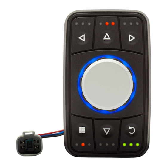
FUNCTION Blue CAN L White CAN H Black Negative battery Red Vbatt. (12-24V) Each end of the CAN bus is terminated with 120Ω resistors in compliance with the standard to minimize signal reflections on the bus. You may need to place a 120Ω resistor between CAN-L and CAN-H. 2. Reference PowerTrack Via Montefeltro, 6 – 20156 Milano (MI) – Italy - 4 - Tel. +39 (02) 3088583 – Fax +39 (02) 33406697 www.blinkmarine.com – info@blinkgroup.com PowerTruck_CANOpen_UM_REV1.5... -
Page 5: Default Settings
3. Default settings Setting Default state or level How to change Baud Rate 125 kbit/s Object 2010h CANopen Node ID 15h Object 2013h CANopen Node State Stop NMT message start CANopen node LED Indicator 3Fh (Maximum brightness 3Fh) Object 2003h Brightness Backlight Brightness 00h (OFF) Object 2003h Periodic Message Disable Object 1800h Transmission Heartbeat Message Disable Object 1017h Boot-up service Active Object 2011h NMT MESSAGES The Network Management messages follow a master-slave structure. Through NMT services, CANopen devices are initialized, started, reset or stopped. All CANopen devices are regarded as NMT slaves. NMT messages have CAN-ID always equal to 00h. 4. Start CANopen node (keypad activation message) Identifier 00h Byte 0... -
Page 6: Reset Canopen Node
6. Reset CANopen node Identifier 00h Byte 0 81h Reset CANopen node Keypad CAN ID Byte 1 XXh 00h: reset all the keypads 15h: reset the keypad with CAN ID = 15h. Byte 2, 7 00h Not used Example: Direction Identifier Format Message To Keypad Std 81 15 7. Stop CANopen node Identifier 00h Byte 0 XXh 02h: Stop CANopen node Byte 1 YYh Keypad CAN ID 00h: stop all the keypads 15h: stop the keypad with CAN ID = 15h. Byte 2, 7 00h Not used... -
Page 7: Pdo Messages
PDO messages PDO (Process Data Object) are fast telegram messages that can simply manage most important functions. There are no answers for this kind of messages. Each PDO message has an equivalent Service Data Object (SDO) message 9. Keys and Encoder state message The keypad must be activated, see NMT Start CANopen Node message. This message is sent by the PowerTrack to indicate the state of the buttons and of the encoder. The state of the buttons is transmitted in the Byte 0. The state of the encoder is represented by 2 counter fields: The Direction counter (Byte1) transmits the number of ticks and the direction of the encoder rotation since the last message sent. The MSB of the counter defines the direction. The Tick counter (Byte 2 and 3) is a two bytes counter incremented each clockwise tick and decremented each counterclockwise tick. Identifier 195h (180 + current CAN ID) Default 195h Byte 0 Keys from #1 to #7 Keys: 1=ON; 0=OFF 0 K7 K6 K5 – K4 K3 K2 K1 Byte 1 Encoder Direction counter X = 0 clockwise, X Y Y Y Y Y Y Y b X = 1 counterclockwise. YYYYYYY = number of Ticks. 1 Turn (360° rotation) = 20 Ticks Byte 2,3 Encoder Tick counter ZZ ZZh Byte 4,7 00h Not used... -
Page 8: Set Led On Message
10. Set LED on message The keypad must be activated, see NMT Start CANopen Node message. Identifier 215h (200 + current CAN ID) Default 215h Byte 0 LG8 LG7 LG6 LG5 - LG4 LG3 LG2 LG1 KEY LED green Byte 1 LG16 LG15 LG14 LG13 – LG12 LG11 LG10 LG9 KEY LED green Byte 2 LR4 LR3 LR2 LR1– 0 0 LG18 LG17 KEY LED green and red Byte 3 LR12 LR11 LR10 LR9 – LR8 LR7 LR6 LR5 KEY LED red Byte 4 0 0 LR18 LR17 – LR16 LR15 LR14 LR13 KEY LED red Byte 5 LR26 LR25 LR24 LR23 – LR22 LR21 LR20 LR19 RING LED red Byte6 LG26 LG25 LG24 LG23 – LG22 LG21 LG20 LG19 RING LED green Byte 7 LB26 LB25 LB24 LB23 – LB22 LB21 LB20 LB19 RING LED blue Examples: Direction Identifier Format Data LED To Keypad 215 Std 00 00 00 00 00 00 00 00... -
Page 9: Set Led Blink Message
11. Set LED blink message The keypad must be activated, see NMT Start CANopen Node message Note: if the blink message is sent when the LED is already on, the LED blinks in alternate mode. Identifier 315h (300 + current CAN ID) Default 315h Byte 0 LG8 LG7 LG6 LG5 - LG4 LG3 LG2 LG1 KEY LED green Byte 1 LG16 LG15 LG14 LG13 – LG12 LG11 LG10 LG9 KEY LED green Byte 2 LR4 LR3 LR2 LR1– 0 0 LG18 LG17 KEY LED green and red Byte 3 LR12 LR11 LR10 LR9 – LR8 LR7 LR6 LR5 KEY LED red Byte 4 0 0 LR18 LR17 – LR16 LR15 LR14 LR13 KEY LED red Byte 5 LR26 LR25 LR24 LR23 – LR22 LR21 LR20 LR19 RING LED red Byte6 LG26 LG25 LG24 LG23 – LG22 LG21 LG20 LG19 RING LED green Byte 7 LB26 LB25 LB24 LB23 – LB22 LB21 LB20 LB19 RING LED blue Examples: Direction Identifier Format Data LED To Keypad 315 Std... -
Page 10: Set Backlight Brightness Level Message
12. Set Backlight brightness level message The keypad must be activated, see NMT Start CANopen Node message Identifier 415h (400 + current CAN ID) Default 415h Byte 0 XXh Green Backlight value 0 – 3Fh (0…100%) Byte 1 YYh Red Backlight value 0 – 3Fh (0…100%) Byte 2 ZZh Blue Backlight value 0 – 3Fh (0…100%) Byte 3, 7 00h Not used Examples: Direction Identifier Format Data LED To keypad 415 Std 00 00 00 00 00 00 00 00 Turn off the backlight To keypad 415 Std 10 00 00 00 00 00 00 00 Turn on backlight green color at brightness 25% To keypad... -
Page 11: Object 1001H: Error Register
Keypad reply 595 Std 00 6C 69 6E 6B 20 4D 61 link Ma To Keypad 615 Std 70 00 00 00 00 00 00 00 Keypad reply 595 Std 17 72 69 6E 65 00 00 00 rine Manufacturer Device Name: PowerTrack – Blink Marine Via Montefeltro, 6 – 20156 Milano (MI) – Italy - 11 - Tel. +39 (02) 3088583 – Fax +39 (02) 33406697 www.blinkmarine.com – info@blinkgroup.com PowerTruck_CANOpen_UM_REV1.5... -
Page 12: Object 1009H: Manufacturer Hardware Revision
16. Object 1009h: Manufacturer Hardware Revision Identifier 615h (600h + current CAN ID) Byte 0 40h Read Device Register Byte 1 09h CAN Object 1009h Byte 2 10h Byte 3, 7 00h Not used Example: Direction Identifier Format Message Data To Keypad 615 Std 40 09 10 00 00 00 00 00 Keypad reply 595 Std 43 09 10 00 33 30 20 56 V 03 Manufacturer Hardware Revision: V 03 17. Object 100Ah: Manufacturer Firmware Revision Identifier 615h (600h + current CAN ID) Byte 0 40h... -
Page 13: Object 1017H: Producer Heartbeat Time
Object 1017h: Producer heartbeat time The producer heartbeat time shall indicate the configured cycle time of the heartbeat. Identifier 600h + current CAN ID Default 615h Byte 0 40h Read Device Register 2Bh Set device register Byte 1 17h CAN Object 1017h Byte 2 10h Byte 3 00h Sub index Byte 4 YYh YYh: Heartbeat time in milliseconds LSByte Byte 5 XXh XXh: Heartbeat time in milliseconds MSByte Byte 5, 7 00h Not used... -
Page 14: Object 1018H: Identity Data
19. Object 1018h: Identity Data Identifier 615h (600h + current CAN ID) Byte 0 40h Read Device Register Byte 1 18h CAN Object 1018h Byte 2 10h Byte 3 00h Number of mapped objects 01h Vendor Id 04h Serial number Byte 4,7 00h Not used Examples: Direction Identifier Format Message Data To Keypad 615 Std 40 18 10 00 00 00 00 00 Keypad reply 595 Std 4F 18 10 00 04 00 00 00 To Keypad 615 Std 40 18 10 01 00 00 00 00... -
Page 15: Object 1401H: Receive Pdo Communication Parm 1
21. Object 1401h: Receive PDO communication Parm 1 Describes the Receive Parameters for the LED blink PDO Message. Identifier 615h (600h + current CAN ID) Byte 0 40h Read Device Register Byte 1 01h CAN Object 1401h Byte 2 14h 00h Number of mapped objects Byte 3 01h COB Id 02h Transmission Type Byte 4,7 00h Not used Examples: Direction Identifier Format Message Data To Keypad 615 Std 40 01 14 00 00 00 00 00 Keypad reply 595 Std 4F 01 14 00 02 00 00 00... -
Page 16: Object 1600H: Receive Pdo Mapping Parameter 0
23. Object 1600h: Receive PDO mapping Parameter 0 Describes the mapping of LED state PDO Message. Identifier 615h (600h + current CAN ID) Byte 0 40h Read Device Register Byte 1 00h CAN Object 1600h Byte 2 16h Byte 3 00h Number of mapped objects 01h PDO Mapping Entry 1 02h PDO Mapping Entry 2 03h PDO Mapping Entry 3 04h PDO Mapping Entry 4 05h PDO Mapping Entry 5 Byte 4,7 00h Not used Examples: Direction Identifier Format Message Data To Keypad 615... -
Page 17: Object 1601H: Receive Pdo Mapping Parameter 1
24. Object 1601h: Receive PDO mapping Parameter 1 Describes the mapping of LED blink state PDO Message. Identifier 615h (600h + current CAN ID) Byte 0 40h Read Device Register Byte 1 01h CAN Object 1601h Byte 2 16h 00h Number of mapped objects Byte 3 01h PDO Mapping Entry 1 02h PDO Mapping Entry 2 03h PDO Mapping Entry 3 04h PDO Mapping Entry 4 05h PDO Mapping Entry 5 Byte 4,7 00h Not used Examples: Direction Identifier Format Message Data To Keypad 615... -
Page 18: Object 1602H: Receive Pdo Mapping Parameter 2
25. Object 1602h: Receive PDO mapping Parameter 2 Describes the mapping of backlight LED state PDO Message. Identifier 615h (600h + current CAN ID) Byte 0 40h Read Device Register Byte 1 02h CAN Object 1602h Byte 2 16h Byte 3 00h Number of mapped objects 01h PDO Mapping Entry 1 02h PDO Mapping Entry 2 03h PDO Mapping Entry 3 Byte 4,7 00h Not used Examples: Direction Identifier Format Message Data To Keypad 615 Std 40 02 16 00 00 00 00 00 Keypad reply 595... -
Page 19: Object 1800H
26. Object 1800h: a) Transmit PDO Communication Parm 0 Identifier 615h (600h + current CAN ID) Byte 0 40h Read Device Register Byte 1 00h CAN Object 1800h Byte 2 18h 00h Number of mapped objects 01h COB Id Byte 3 02h Transmission Type 05h Event Timer Byte 4,7 00h Not used Example: Direction Identifier Format Message Data To Keypad 615 Std 40 00 18 00 00 00 00 00 Keypad reply 595... -
Page 20: Object 1A00H Transmit Pdo Mapping Parameter
27. Object 1A00h Transmit PDO Mapping Parameter Describes the mapping of KEY and Encoder state PDO Message. Identifier 615h (600h + current CAN ID) Byte 0 40h Read Device Register Byte 1 00h CAN Object 1A00h Byte 2 1Ah Byte 3 00h Number of mapped objects 01h PDO Mapping Entry 1 02h PDO Mapping Entry 2 03h PDO Mapping Entry 3 Byte 4,7 00h Not used Example: Direction Identifier Format Message Data To Keypad 615 Std 40 00 1A 00 00 00 00 00 Keypad reply 595 Std... -
Page 21: B) Sub 2 - Encoder Direction Counter
b) Sub 2 - Encoder direction counter This module contains the Encoder direction counter. The command works only in the pre- operational state. Identifier 615h (600h + current CAN ID) Byte 0 40h Read Device Register Byte 1 00h CAN Object 2000h Byte 2 20h Byte 3 02h Sub index Byte 4,7 00h Not used Keypad reply: Identifier 595h (580h + current CAN ID) Byte 0 4Fh Byte 1 00h CAN Object 2000h Byte 2 20h Byte 3 02h Sub index Byte 4 XXh Bit 7: encoder direction 0: Clockwise •... - Page 22 29. Object 2001h: LED state a) Sub 1 – LED green state Identifier 615h (600h + current CAN ID) Byte 0 27h Set Device Register Byte 1 01h CAN Object 2001h Byte 2 20h Byte 3 01h Sub index Byte 4 LG8 LG7 LG6 LG5 - LG4 LG3 LG2 LG1 LED green Byte 5 LG16 LG15 LG14 LG13 – LG12 LG11 LG10 LG9 LED green Byte 6 0 0 0 0 – 0 0 LG18 LG17 LED green Byte 7 00h Not used Examples: Direction Identifier Format Data LED To Keypad...
- Page 23 c) Sub 3 - LED green blink state Note: if the blink message is sent when the LED is already on, the LED blinks in alternate mode. Identifier 615h (600h + current CAN ID) Byte 0 27h Set Device Register Byte 1 01h CAN Object 2001h Byte 2 20h Byte 3 03h Sub index Byte 4 LG8 LG7 LG6 LG5 - LG4 LG3 LG2 LG1 LED green blink Byte 5 LG16 LG15 LG14 LG13 – LG12 LG11 LG10 LG9 LED green blink Byte 6 0 0 0 0 – 0 0 LG18 LG17 LED green blink Byte 7 00h Not used Examples: Direction Identifier Format Data LED To Keypad 615 Std...
- Page 24 30. Object 2002h: LED RING state The RING LEDs can be illuminated as indicator and backlight function as well. Each LED on the RING in off state (not used as indicator) will be illuminated according to the backlight command. a) Sub 1 –RING LED green state Identifier 615h (600h + current CAN ID) Byte 0 2Fh Set Device Register Byte 1 02h CAN Object 2002h Byte 2 20h Byte 3 01h Sub index Byte 4 LG26 LG25 LG24 LG23 – LG22 LG21 LG20 LG19 LED green Byte 5,7 00h Not used Examples: Direction Identifier Format Data LED To Keypad 615...
- Page 25 c) Sub 3 RING LED blue state Identifier 615h (600h + current CAN ID) Byte 0 2Fh Set Device Register Byte 1 02h CAN Object 2002h Byte 2 20h Byte 3 03h Sub index Byte 4 LB26 LB25 LB24 LB23 – LB22 LB21 LB20 LB19 LED blue Byte 5,7 00h Not used Examples: Direction Identifier Format Data LED To Keypad 615 Std 2F 02 20 03 00 00 00 00 Turn off all the blue LED To Keypad 615 Std 2F 02 20 03 02 00 00 00 Blue LED #20 ON To Keypad...
- Page 26 e) Sub 5 –RING LED red blink state Note: if the blink message is sent when the LED is already on, the LED blinks in alternate mode. Identifier 615h (600h + current CAN ID) Byte 0 2Fh Set Device Register Byte 1 02h CAN Object 2002h Byte 2 20h Byte 3 05h Sub index Byte 4 LR26 LR25 LR24 LR23 – LR22 LR21 LR20 LR19 Red LED blink Byte 5,7 00h Not used Examples: Direction Identifier Format Data LED To Keypad 615 Std 2F 02 20 05 00 00 00 00 No red LED blink To Keypad 615 Std 2F 02 20 05 04 00 00 00 Red LED #21 blinks...
-
Page 27: Object 2003: Brightness Level
31. Object 2003: Brightness Level a) Set Indicator LEDs brightness level Identifier 615h (600h + current CAN ID) Byte 0 2Fh Set Device Register Byte 1 03h CAN Object 2003h Byte 2 20h Byte 3 01h Sub index Byte 4 XXh Intensity 00h-3Fhà min-100% Byte 5,7 00h Not used Example: Direction Identifier Format Message Data To Keypad 615 Std 2F 03 20 01 10 00 00 00 Brightness = 25% Keypad reply 595... -
Page 28: D) Set Blue Leds Backlight Brightness Level
d) Set blue LEDs backlight brightness level Identifier 615h (600h + current CAN ID) Byte 0 2Fh Set Device Register Byte 1 03h CAN Object 2003h Byte 2 20h Byte 3 04h Sub index Byte 4 XXh Intensity 00h-3Fhà 0-100% Byte 5,7 00h Not used Example: Direction Identifier Format Message Data To Keypad 615 Std 2F 03 20 04 25 00 00 00 Brightness = 62,5% Keypad reply 595 Std 60 03 20 04 00 00 00 00 e) Set startup Indicator LEDs brightness level Identifier... -
Page 29: G) Set Startup Red Leds Backlight Brightness Level
g) Set startup red LEDs backlight brightness level Identifier 615h (600h + current CAN ID) Byte 0 2Fh Set Device Register Byte 1 03h CAN Object 2003h Byte 2 20h Byte 3 07h Sub index Byte 4 XXh Intensity 00h-3Fhà 0-100% Byte 5,7 00h Not used Example: Direction Identifier Format Message Data To Keypad 615 Std 2F 03 20 07 30 00 00 00 Brightness = 75% Keypad reply 595 Std 60 03 20 07 00 00 00 00 h) Set startup blue LEDs backlight brightness level... -
Page 30: Object 2010H: Baud Rate Setting
32. Object 2010h: Baud rate setting Identifier 615h (600h + current CAN ID) Byte 0 2Fh Set Device Register Byte 1 10h CAN Object 2010h Byte 2 20h Byte 3 00h Sub index 00h 1000k Byte 4 01h Reserved (force to 125k) 02h 500k 03h 250k 04h 125k (Default) 05h Reserved (force to 125k) 06h 50k 07h 20k Byte 5,7 00h Not used Example: Direction Identifier Format... -
Page 31: Object 2012H: Set Device Active On Startup
34. Object 2012h: Set device active on startup If keypad is active on startup don’t need the Start CANopen command from host. Identifier 600h + current CAN ID Default 615h Byte 0 2Fh Set Device Register Byte 1 12h CAN Object 2012h Byte 2 20h Byte 3 00h Sub index Byte 4 XXh 00h: Not active 01h: Active Byte 5,7 00h Not used Example: Direction Identifier Format Message Data To Keypad 615 Std 2F 12 20 00 01 00 00 00 Set device active on startup Keypad reply 595... -
Page 32: Object 2100H: Set Demo Mode
Object 2100h: Set DEMO mode This message enables the Demo mode function. Demo mode is a special feature that consists in different LED states for each button pressing. Refer to the appendix ‘’Demo mode instructions’’ to try these special features. Disconnect and reconnect the keypad after the enable message to enter this mode. To exit the Demo mode, send the Disable Demo mode command or another command message. -
Page 33: Appendix: Demo Mode Instructions
APPENDIX: DEMO Mode instructions In DEMO Mode you can try these functions by pressing buttons on the PowerTrack. For the Key 1, each time that you press the button, there are different steps in this sequence: No LEDs on and no backlight; All LEDs green on and backlight red; All LEDs red on and backlight green; Keys LEDs amber/orange on, keys backlight blue on and encoder ring backlight red-green on Return in step 1. Pressing Key 2 you can see keys LEDs backlight white color on, while keys LEDs and encoder/ring backlight blink red and green in alternate mode. For the Key 3, each time that you press the button, you can change backlight in this sequence: Red; Green; Blue, red cursor on the encoder ring; Amber/orange and encoder yellow/green, red cursor on the encoder ring; Cyan, red cursor on the encoder ring; Magenta, red cursor on the encoder ring; White/light blue, red cursor on the encoder ring; Return in step 1. Pressing Key 4 you can see backlight blue. In the case that you press key 5, 6 and 7 and/or rotate the encoder (clockwise or counterclockwise) there are no events. Via Montefeltro, 6 – 20156 Milano (MI) – Italy - 33 - Tel. -
Page 34: Revision History
39. Revision History Related Manual Date Comment Revision version 18/04/2016 1.3 1.4 14/10/2016 1.4 Updated examples for the object 1800h set periodic 1.4 transmission 20/02/2018 1.5 New release: 2.x Added the sentence concerning keypad • activation in every PDOs commands Replaced the symbol ‘h’(hexadecimal) with • the correct one ‘b’ (binary) in the ‘’keys and encoder state’’ table Checked and eventually corrected the • messages of transmission/reply of command objects Corrected the minimum value of brightness • for indicator LEDs brightness level command Added appendix DEMO Mode instructions • Added the SET CAN protocol command • Via Montefeltro, 6 – 20156 Milano (MI) – Italy - 34 - Tel.
Need help?
Do you have a question about the POWERTRACK and is the answer not in the manual?
Questions and answers