Table of Contents
Advertisement
Quick Links
Summary:
1.
How to connect the wires: ................................................................................................................ 3
2.
Reference ........................................................................................................................................... 4
3.
Message header description ............................................................................................................. 5
4.
General Data Format ......................................................................................................................... 5
5.
Default Settings ................................................................................................................................. 6
6.
Key Contact state (01h) ..................................................................................................................... 7
7.
Encoder 1 state message (02h) ......................................................................................................... 8
8.
Encoder 2 state message (03h) ......................................................................................................... 9
9.
Analog input message (04h) ............................................................................................................ 10
10.
Digital input message (0Ah) ............................................................................................................. 11
11.
Key-LED command (01h) ................................................................................................................. 12
12.
Encoder LED command (0Ah) .......................................................................................................... 13
13.
Set LED indicators brightness level (02h) ........................................................................................ 14
14.
Set backlight level (03h) .................................................................................................................. 14
15.
Set startup keys message(28h) ........................................................................................................ 14
16.
Get software revision (2Ah) ............................................................................................................. 15
17.
Set startup LED show (34h) ............................................................................................................. 15
18.
Set startup encoder 1 tick counter value (61h) ............................................................................... 16
19.
Set startup encoder 2 tick counter value (62h) ............................................................................... 16
20.
Set analog input message period (6Ah) ........................................................................................... 17
21.
Set TOP position encoder 1 (6Bh) .................................................................................................... 17
22.
Set TOP position encoder 2 (6Ch) .................................................................................................... 18
23.
Set Destination Address (6Eh) ......................................................................................................... 19
24.
Baud rate setting (6Fh) .................................................................................................................... 19
25.
Set Source Address (70h) ................................................................................................................. 20
26.
Periodic key-state transmission (71h) ............................................................................................. 20
27.
Event state transmission (72h) ........................................................................................................ 21
28.
LED Acknowledgment (73h) ............................................................................................................ 21
29.
Address Claim at boot (74h) ............................................................................................................ 22
30.
Heartbeat message (75h) ................................................................................................................ 23
31.
Key-state message period (77h) ...................................................................................................... 24
1/30
PKP3500-MT_J1939UM_REV1.2
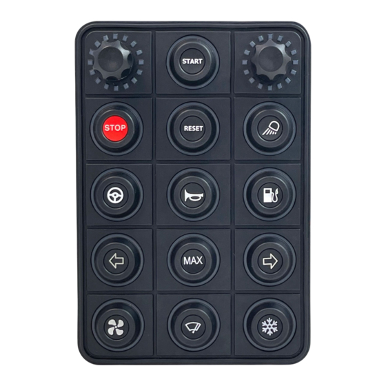
PKP3500-MT J1939
Advertisement
Table of Contents

Related Manuals for Blink Marine PKP3500-MT


Summary of Contents for Blink Marine PKP3500-MT
-
Page 1: Table Of Contents
PKP3500-MT J1939 Summary: How to connect the wires: ........................ 3 Reference ............................4 Message header description ......................5 General Data Format ......................... 5 Default Settings ..........................6 Key Contact state (01h) ........................7 Encoder 1 state message (02h) ......................8 Encoder 2 state message (03h) ...................... - Page 2 Start Demo mode(7Ah)........................24 Default backlight brightness level (7Bh) ..................25 Default LED indicators brightness level (7Ch) ................. 25 Default backlight color (7Dh) ......................26 Set CAN protocol ..........................26 APPENDIX: DEMO Mode instructions ......................27 APPENDIX 2: Input application examples ....................28 Revision history ..........................
-
Page 3: How To Connect The Wires
1. How to connect the wires: Power Supply Connector Connector: AMPHENOL AT04-4P or DEUTSCH DT04-4P COLOUR FUNCTION Blue CAN L White CAN H Black Negative battery Vbatt. (12-24V) Input Signal Connector Connector: MOLEX 39-013-069 (or -063) COLOUR FUNCTION Power +5V Yellow Blue Grey... -
Page 4: Reference
2. Reference PKP3500-MT www.blinkmarine.com PKP3500-MT_J1939UM_REV1.2 4/30... -
Page 5: Message Header Description
3. Message header description The 29-bit CAN identifier used in J1939 is structured in the following way. Priority Reserved Data Page PDU Format PDU Specific Source Address 3 bits 1 bit 1 bit 8 bits 8 bits 8 bits The proprietary format used by PKP keypads is defined as follows: Priority = 6. -
Page 6: Default Settings
5. Default Settings Setting Default state or level How to change CAN bus baud rate 250 kbit/s Command 6Fh Source address Command 70h Keypad identifier Command 70h Destination address Command 6Eh Heartbeat Disabled Command 75h Periodic key-state message transmission Disabled Command 71h Key-state message period 100ms... -
Page 7: Key Contact State (01H)
6. Key Contact state (01h) This message is sent by the keypad to indicate the state of the contacts. The destination address is set to FFh: broadcast message. See chapter 2 for Key number reference. Byte 0 Header bytes Byte 1 Byte 2 Key Contact state Byte 3... -
Page 8: Encoder 1 State Message (02H)
7. Encoder 1 state message (02h) This message is sent by the keypad to indicate the state of the encoder 1. The destination address is set to FFh: broadcast message. Note: the encoder 1 is identified with the key number 1. See chapter 2 for further details. -
Page 9: Encoder 2 State Message (03H)
8. Encoder 2 state message (03h) This message is sent by the keypad to indicate the state of the encoder 2. The destination address is set to FFh: broadcast message. Note: the encoder 2 is identified with the key number 11. See chapter 2 for further details. -
Page 10: Analog Input Message (04H)
9. Analog input message (04h) This message transmits periodically the analog values with 8-bit resolution of each of the four inputs. The default transmission period is 80ms, but it is possible to change by the configuration command Set analog input message period (6Ah). -
Page 11: Digital Input Message (0Ah)
10. Digital input message (0Ah) By this command message, it is possible to read the digital input value. Note: please refer to chapter 1 for the connector pinout. Note 2: it is possible to connect up to 4 inputs 0-5V. For application examples please refer to Appendix Warning: the input voltage range is from 0V to 5V. -
Page 12: Key-Led Command (01H)
11. Key-LED command (01h) The following message sent to the keypad allows to switch on/off the Key-LED indicators with the color and state shown in the table below. chapter 2 for Key-LED number reference. Byte 0 Header bytes Byte 1 Byte 2 Key-LED command Byte 3... -
Page 13: Encoder Led Command (0Ah)
12. Encoder LED command (0Ah) The following message sent to the keypad allows to switch on/off the encoder LED indicators with the state shown in the table below. chapter 2 for encoder LED number reference. Byte 0 Header bytes Byte 1 Byte 2 Encoder LED command Byte 3... -
Page 14: Set Led Indicators Brightness Level (02H)
13. Set LED indicators brightness level (02h) This message sets the value of the LED indicators brightness level. The value can be set from 0 to 3Fh (min-100%) of the LED dimming range. NOTE: this setting has temporary effect and at the startup comes back to the default value. If the default value is desired to change, please refer to the Command 7Ch. -
Page 15: Get Software Revision (2Ah)
Get software revision (2Ah) Byte 0 Header bytes Byte 1 Byte 2 Get software revision Byte 3,7 Not used Answer: Byte 0 Header bytes Byte 1 Byte 2 Get software revision Byte 3,6 XXh XXh XXh XXh SW revision ASCII Byte 7 Not used Example... -
Page 16: Set Startup Encoder 1 Tick Counter Value (61H)
Set startup encoder 1 tick counter value (61h) The following command allows to set the desired encoder 1 tick counter value at the startup. NOTE: in case the TOP position has been set, if it is selected a startup counter value higher than the TOP position, the counter starts from the TOP position. -
Page 17: Set Analog Input Message Period (6Ah)
20. Set analog input message period (6Ah) This configuration message allows to disable the periodic transmission or change the default transmission period of the analog input message 04h. Byte 0 Header bytes Byte 1 Byte 2 Set analog input message period XXh: Period in ms ÷... -
Page 18: Set Top Position Encoder 2 (6Ch)
22. Set TOP position encoder 2 (6Ch) The following command allows to set the TOP position value for the tick counter of encoder 2. Note: if the value 00h is selected the maximum tick counter value achievable is 65535. Note 2: the encoder 1 is identified with the key number 11. See chapter 2 for further details. -
Page 19: Set Destination Address (6Eh)
23. Set Destination Address (6Eh) This message is used to set the addressee node of the Key Contact state transmitted by the keypad. The default destination address is FFh (broadcast). Byte 0 Header bytes Byte 1 Byte 2 Set Destination Address XX: CAN Destination Address Byte 3 From 00h to FFh... -
Page 20: Set Source Address (70H)
25. Set Source Address (70h) This message is used to change the keypad CAN Source Address and/or the Keypad Identifier. Either or both the Source Address or Keypad Identifier may be changed independently. Connecting only one keypad to the bus when changing the keypad address is recommended. If an invalid value is chosen, then no change is done to the stored value. -
Page 21: Event State Transmission (72H)
27. Event state transmission (72h) This message enables or disables event-driven key state transmissions. When this feature is enabled, the keypad transmits the state of a contact at the time that the contact changes state (pressed or released). Byte 0 Header bytes Byte 1 Byte 2... -
Page 22: Address Claim At Boot (74H)
29. Address Claim at boot (74h) This message enables or disables the address claim procedure. Byte 0 Header bytes Byte 1 Byte 2 Address claim at boot Byte 3 00h Disabled (default) 01h Enabled Byte 4,7 Not used Example: Direction Identifier Format Message... -
Page 23: Heartbeat Message (75H)
30. Heartbeat message (75h) This command enables or disables the transmission of Heartbeat message. This message is designed to indicate to other devices on the bus that this unit continues to function. Byte 0 Header bytes Byte 1 Byte 2 Heartbeat message Byte 3 00h Disabled (default) -
Page 24: Key-State Message Period (77H)
31. Key-state message period (77h) This message sets the period time for the PERIODIC KEY-STATE TRANSMISSION (71h). Byte 0 Header bytes Byte 1 Byte 2 Key-state message period XX: Period in milliseconds ÷ 10 Byte 3 From 05h (50ms) to FEh (2.54 sec) Byte 4,7 Not used Example:... -
Page 25: Default Backlight Brightness Level (7Bh)
33. Default backlight brightness level (7Bh) This message sets the default value of the backlight brightness level. The value can be set from 0 to 3Fh (0-100%) of the brightness range. Byte 0 Header bytes Byte 1 Byte 2 Default backlight brightness level XX: Value Byte 3 From 00h (0%) to 3Fh (100%) -
Page 26: Default Backlight Color (7Dh)
35. Default backlight color (7Dh) This message sets the default color of the backlight. Byte 0 Header bytes Byte 1 Byte 2 Default backlight color XX: color 01: red 02: green 03: blue Byte 3 04: yellow 05: cyan 06: magenta 07: white/light blue 08: amber/orange 09: yellow/green... -
Page 27: Appendix: Demo Mode Instructions
APPENDIX: DEMO Mode instructions In DEMO Mode you can try the following functions by pressing keys on the PKP3500-MT. Entering this mode, you turn the encoder LEDs 1-17 and the key-LED indicators on with red color (opening feature); each time you press the key 1 you can change the color of the indicators with the following sequence: Red;... -
Page 28: Appendix 2: Input Application Examples
APPENDIX 2: Input application examples This chapter shows a list of possible input applications. NOTE: the power supply and ground available on the Input Signal Connector must be used for the external connected devices. 1. Switch high side on input 3: 2. - Page 29 3. Digital active signal on input 2: 4. Active analog sensor: • Pressure transducer – signal on input 0 • Hall effect position sensor – signal on input 0 5. The use of passive sensors such as NTC thermistors, potentiometers, and all kind of variable resistors is not recommended! www.blinkmarine.com PKP3500-MT_J1939UM_REV1.2...
-
Page 30: Revision History
37. Revision history Manual Date Comment Revision 16/01/2023 First release Second release: 08/05/2023 • Updated description in the chapters 7-8 Third release: • Added Set startup encoder 1 tick counter value (61h); 16/05/2023 • Added Set startup encoder 2 tick counter value (62h). www.blinkmarine.com PKP3500-MT_J1939UM_REV1.2 30/30...
Need help?
Do you have a question about the PKP3500-MT and is the answer not in the manual?
Questions and answers