Table of Contents
Advertisement
Quick Links
THE PRESENT MANUAL IS FOR REFERENCE ONLY AND MIGHT BE NOT UP TO DATE TO THE LATEST VERSION.
Via Montefeltro, 6 – 20156 Milano (MI) – Italy
Tel. +39 (02) 3088583 – Fax +39 (02) 33406697
www.blinkmarine.com – info@blinkgroup.com
PK-1400
J1939 USER MANUAL
PLEASE CONTACT US FOR GETTING THE MOST UPDATED FILE
PK-1400_J1939_UM_REV1.2
Advertisement
Table of Contents

Subscribe to Our Youtube Channel
Related Manuals for Blink Marine PK-1400


Summary of Contents for Blink Marine PK-1400
- Page 1 PK-1400 J1939 USER MANUAL THE PRESENT MANUAL IS FOR REFERENCE ONLY AND MIGHT BE NOT UP TO DATE TO THE LATEST VERSION. PLEASE CONTACT US FOR GETTING THE MOST UPDATED FILE Via Montefeltro, 6 – 20156 Milano (MI) – Italy Tel. +39 (02) 3088583 – Fax +39 (02) 33406697 www.blinkmarine.com – info@blinkgroup.com PK-1400_J1939_UM_REV1.2...
-
Page 2: Table Of Contents
Table of contents How to connect Deutsch 4 pin: ...................... 3 Reference ............................. 3 Message header description ........................ 4 General Data Format .......................... 4 Default settings ............................ 5 Key Contact state (01h) ........................ 5 LED command (01h) .......................... 6 Set LED brightness level (02h) ...................... 7 Set backlight level (03h) ........................ 7 Set startup keys message(28h) ...................... 7 Get software revision (2Ah) ........................ 8 Set startup LED show (34h) ........................ 8 Set Source Address (70h) ........................ 9 Periodic state transmission (71h) ...................... 9 Event state transmission (72h) ...................... 1 0 LED Acknowledgment (73h) ....................... 1 0 Address Claim at boot (74h) ....................... 1 1 Heartbeat (75h) .......................... 1 2... -
Page 3: How To Connect Deutsch 4 Pin
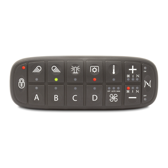
1. How to connect Deutsch 4 pin: PIN COLOUR FUNCTION Blue CAN L White CAN H Black Negative battery Red Vbatt. (12-24V) Each end of the CAN bus is terminated with 120Ω resistors in compliance with the standard to minimize signal reflections on the bus. You may need to place a 120Ω resistor between CAN-L and CAN-H. 2. Reference Key: LED: Via Montefeltro, 6 – 20156 Milano (MI) – Italy - 3 - Tel. +39 (02) 3088583 – Fax +39 (02) 33406697 www.blinkmarine.com –... -
Page 4: Message Header Description
3. Message header description The 29-bit CAN identifier used in J1939 is structured in the following way. Priority Reserved Data Page PDU Format PDU Specific Source Address 3 bits 1 bit 1 bit 8 bits 8 bits 8 bits The proprietary format used by PK and PKP keypads is defined as follows: Priority = 6. Reserved = 0. Data page = 0. PDU Format = EFh (the message is addressable). PDU Specific = Destination Address. Parameter Group Number (PGN) = 61184 (EF00h). An example of CAN identifier of messages sent to the keypad is 18EF2100h where: 21h is the destination address (keypad) 00h is the source address. An example of CAN identifier of messages sent by the keypad is 18EFFF21h where: FFh refers to broadcast messages (no specific destination address) 21h is the source address (keypad). 4. General Data Format The proprietary protocol has defined a general format for the data fields in the PGN 61184. The format consists of: 1 header field (2 bytes) 1 command byte 8 bytes (the remaining field) are defined specifically for each command. The data length is 8 bytes, unused bits and bytes are set to all 1’s (0xFF). -
Page 5: Default Settings
5. Default settings Setting Default status or level How to change CAN bus Baud Rate 250 kbit/s Command 6Fh Source Address 21h Command 70h Keypad Identifier 21h Command 70h Heartbeat Message Disable Command 75h Periodic state Disable Command 71h transmission Periodic transmission 100ms Command 77h period Event state transmission Enable Command 72h Address claim Disable Command 74h LED brightness level 3Fh Command 7Ch Startup backlight OFF Command 7Bh Startup LED show Complete LED Sequence Command 34h Backlight color Amber... -
Page 6: Led Command (01H)
7. LED command (01h) This message is sent to the keypad to set the state of the LED indicators. See chapter 2 for Key and LED number reference. Byte 0 04h Header bytes Byte 1 1Bh Byte 2 01h LED command message Byte 3 XXh XX: PK1400 LED number Byte 4 YYh LED Color 00: off 01: red 02: green 03: color 03 04: color 04 Byte 5 ZZh LED State 00: off 01: on 02: blink 03: alternate blink Byte 6 WWh LED Secondary Color (only for alt blink) 00: off 01: red 02: green 03: color 03 04: color 04 Byte 7 FFh... -
Page 7: Set Led Brightness Level (02H)
Set LED brightness level (02h) This message sets the value of the indicator LED brightness. The value can be set from 0 to 3Fh from a minimum value to 100% of the LED dimming range. Byte 0 04h Header bytes Byte 1 1Bh Byte 2 02h LED brightness level message Byte 3 XXh XX: Dim Value (default 3Fh) From 00h (min) to 3Fh (100%) Byte 4,7 FFh Not used Example: Direction Identifier Format Message Data To keypad 18EF2100h Ext 04 1B 02 20 FF FF FF FF Brightness set to 50% 8. Set backlight level (03h) This message sets the value of the backlight LED brightness. The value can be set from 0 to 3Fh for 0 to 100% of the brightness range. Byte 0 04h Header bytes... -
Page 8: Get Software Revision (2Ah)
10. Get software revision (2Ah) Byte 0 04h Header bytes Byte 1 1Bh Byte 2 2Ah Get software revision Byte 3,7 FFh Not used Answer: Byte 0 04h Header bytes Byte 1 1Bh Byte 2 2Ah Get software revision Byte 3,6 XXh XXh XXh XXh SW revision ASCII Byte 7 00h Not used Example: Direction Identifier Format Message Data To keypad 18EF2100h Ext 04 1B 2A FF FF FF FF FF Get software revision From... -
Page 9: Set Source Address (70H)
Set Source Address (70h) This message is used to change the keypad CAN Source Address and/or the Keypad Identifier. Either or both the Source Address or Keypad Identifier may be changed independently. Connecting only one keypad to the bus when changing the keypad address is recommended. If an invalid value is chosen, then no change is done to the stored value. -
Page 10: Event State Transmission (72H)
Event state transmission (72h) This message enables or disables event driven key state transmissions. When this feature is enabled, the keypad transmits the state of a contact at the time that the contact changes state (pressed or released). Byte 0 04h Header bytes Byte 1 1Bh Byte 2 72h Event state transmission Byte 3 XXh XX: 00h Disabled 01h Enabled (default) Byte 4,7 FFh Not used Example: Direction Identifier Format Message Data 18EF2100h Ext... -
Page 11: Address Claim At Boot (74H)
16. Address Claim at boot (74h) This message enables or disables the address claim procedure. Byte 0 04h Header bytes Byte 1 1Bh Byte 2 74h Address claim at boot Byte 3 XXh XX: 00h Disabled (default) 01h Enabled Byte 4,7 FFh Not used Example: Direction Identifier Format Message Data To keypad 18EF2100h Ext 04 1B 74 01 FF FF FF FF Enable address claim Address claiming procedure: Under normal operation, the keypad application sends an Address Claim parameter group at start up and waits up to 250 ms for the other devices connected to the same network to send a message containing the device’s address and name. The keypad checks every response and compares the names to see who has the highest priority. If a device is already using the address and has a higher priority, then a new address is selected, and the process starts over. If the keypad has a higher priority than the device in use then it... -
Page 12: Heartbeat (75H)
17. Heartbeat (75h) This message enables or disables the transmission of Heartbeat message. This message is designed to indicate to other devices on the bus that this unit continues to function. Byte 0 04h Header bytes Byte 1 1Bh Byte 2 75h Heartbeat Byte 3 XXh XX: 00h Disabled (default) 01h Enabled Byte 4 YYh YY: Period in milliseconds ÷ 10 From 05h (50ms) to FEh (2.54 sec) Byte 5,7 FFh Not used Example: Direction Identifier Format Message Data To keypad 18EF2100h Ext 04 1B 75 01 32 FF FF Set heartbeat enabled with 500ms period. Heartbeat generated message: Byte 0 04h Header bytes Byte 1 1Bh... -
Page 13: Start Demo Mode(7Ah)
Start Demo mode(7Ah) This message enables the Demo mode function. Demo mode is a special feature that consists in different LED states for each button pressing. Refer to the appendix “Demo mode instructions” to try these special features. Disconnect and reconnect the keypad after the enable message to enter this mode. To exit the Demo mode, send the Disable Demo mode command or another command message. -
Page 14: Led Dim At Startup (7Ch)
21. LED dim at startup (7Ch) This message sets the value of the indicator LED brightness at keypad power up. The value can be set from a minimum value to 3Fh for 0 to 100% of the LED dimming range. Byte 0 04h Header bytes Byte 1 1Bh Byte 2 7Ch LED dim at startup Byte 3 XXh XX: Value From 00h (min) to 3Fh (100%) Byte 4,7 FFh Not used Example: Direction Identifier Format Message Data To keypad 18EF2100h Ext 04 1B 7C 10 FF FF FF FF LED dim set to 25% 22. Set backlight color (7Dh) This message sets the color of the backlight. Byte 0 04h Header bytes... -
Page 15: Baud Rate Setting (6Fh)
23. Baud rate setting (6Fh) This message is used to change the baud rate of the CAN bus. Connecting only one keypad to the bus when changing the baud rate is recommended. If an invalid value is chosen, then no change is done to the stored value. Byte 0 04h Header bytes Byte 1 1Bh Byte 2 6Fh Set baud rate message Byte 3 02h 500kbit/s 03h 250kbit/s Byte 4,7 FFh Not used Example: Direction Identifier Format Message Data To keypad 18EF2100h Ext 04 1B 6F 02 FF FF FF FF Set baud rate = 500kbit/s 24. Set CAN protocol This set of messages are used to change to the desired CANbus protocol. Change from J1939 to CANopen: •... -
Page 16: Appendix: Demo Mode Instructions
APPENDIX: DEMO Mode instructions In DEMO Mode you can try the following functions by pressing buttons on the PK1400. Entering this mode, you turn on key-LEDs with color red. For the key 1, each time you press the button you can change the color of key-LEDS with this sequence: Green; Color 03 Color 04 OFF. For the key 4, each time that you press the button, there are different steps in this sequence: Complete LED show of all colors: at first with red, then green, color 03 , and at the end color 04 Turning on/off each single key-LED with the possibility to change color pressing key Pause step 2; Return to the starting demo mode state. If you press the other keys, you have no effect. 25. Revision history Date Manual Comment Related SW Revision version 03/02/2017 1.0 First Release 23/11/2017 1.1 Second Release SW 2.x Replaced 0% with min value for LED brightness Corrected heartbeat generated message with exact number of keys Updated LED acknowledgement...
Need help?
Do you have a question about the PK-1400 and is the answer not in the manual?
Questions and answers