Table of Contents
Advertisement
Quick Links
IN PARTNERSHIP WITH
INSTRUCTION MANUAL
GE3
WARNING
Read and understand this entire
owner's manual, including all
safety information, before
plugging in or using this product.
Failure to do so could result in
fire, electric shock, or serious
personal injury.
GE3_06
ELECTRIC FIREPLACE
INSERT
Caution
Keep this owner's manual for
future reference. If you sell or give
this product away, make sure this
manual accompanies this product.
Advertisement
Table of Contents

Related Manuals for Valor GE3


Summary of Contents for Valor GE3
- Page 1 IN PARTNERSHIP WITH INSTRUCTION MANUAL ELECTRIC FIREPLACE INSERT WARNING Caution Read and understand this entire Keep this owner’s manual for owner’s manual, including all future reference. If you sell or give safety information, before this product away, make sure this plugging in or using this product.
- Page 2 Ce guide est disponible en français sur demande. Distributed in Canada and USA exclusively by Valor Fireplaces — Head Offi ce #190, 2255 Dollarton Hwy, North Vancouver, BC V7H 3B1 Phone: 604.984.3496 Email: info@valorfi replaces.com Manufactured by Charlton & Jenrick Ltd Unit D, Staff...
-
Page 3: Table Of Contents
Appliance ..............19 Fuel Bed ...............19 Front ................19 Operating Instructions ........20 Manual Control ............20 Remote Control ............21 App Control ..............23 Maintenance ............ 24 Service Parts List ..........25 Wiring Diagram ..........27 Valor Electric Fireplaces Warranty ....28... -
Page 4: Important Safety Information
fi replace. Failure to follow these instructions may result in possible fi re hazard and will void the warranty. Replacement manuals are available by contacting the Valor Customer Service at 1-800-468-2567, or by visiting valorfi replaces.com. - Page 5 Important Safety Information other appliances into the same circuit as this heater. WARNING NEVER plug this heater into an outlet that • DO NOT depend on the ON/OFF switch as is old, cracked, or has any loose wires or the sole means of disconnecting power connections.
-
Page 6: Appliance Certifications
Appliance Certifications This device has been tested in accordance with the • Connect the equipment into an outlet on a circuit dif- CSA Standards for fi xed and location-dedicated electric ferent from that to which the receiver is connected. room heaters in the United States and Canada. •... -
Page 7: Technical Specifications
9400 BTU/hr set to voltage to be used by the fireplace. If 240 V is to be used, it must be hardwired. Model No.: GE3 Power for fl ame eff ect: 16 W Power for Mood Light: 9 W To change voltage from 120V to 240V, access the switch inside the fi... -
Page 8: Pack Content
Pack Content 1. Unpack the fi replace carefully and make sure that the appliance is intact with no signs of damage caused by transport and no part has been exposed to water. If in doubt, do not use the appliance and contact your retailer. -
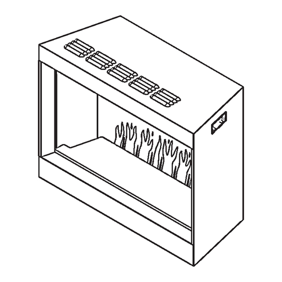
Page 9: Appliance Dimensions
Appliance Dimensions Clearances from combustibles 21-11/16 [550] Top: 0 Vents 6’ (72”) Electrical cord Bottom: 0 3/16 [5] with 3-prong grounded plug Sides: 0 Rear: 0 Front: Minimum 39” [1 m] 27 [685] Vents 3/16 [5] Levelling bolts: inch [mm] 3/16 [5] NOTE: Appliance equipped with levelling bolts for... -
Page 10: Accessories
Accessories Fuel Beds This appliance is supplied with black glass embers and vermiculite. In addition, three optional log sets are off ered to complement the embers/vermiculite. • GE3DWK—Driftwood Log Kit • GE3SWK—Splitwood Log Kit • GE3BLK—Birch Log Kit Mood Lighting This appliance can be installed with optional LED strip lighting, up to 9 W. -
Page 11: Fronts & Backing Plates
Accessories Fronts & Backing Plates Fronts and optional backing plates are off ered separately to help fi nish the appliance contour, either when installed in the chimney or framed into the wall. Follow the instructions supplied with each front/ backing plate. •... - Page 12 Accessories Fronts & Backing Plates • GE3EDPW—4-Sided Edgemont Front. Requires GE34SBP1 or GE3SK1. NOTE: When installed with the GE3SK1, the front hangs 1/8” below the bottom of the fi replace. 29-13/16” 11/16” 11-11/16” 21-9/16” 20-3/16” Front plate ends below 1/8” GE3EDPW + GE3SK1 bottom of appliance •...
-
Page 13: Installation Instructions
Check the dimensions carefully to The following is only given as a general guide because it ensure the GE3 will fi t behind any raised curb (some can be installed in diff erent ways. curbs may be removed separately from the refractory This appliance is intended to be installed either in an base). -
Page 14: Installing Into A Built-In Cavity
Installation Instructions Preparation Installing Into a Built-in Cavity • Prepare the framing. As a general guide only, see picture below. NOTE Ensure a firm flat positioning of the appliance to avoid vibration and movement of the appliance after finishing. • Wall fi nish. Hard surfaces can amplify sound. Con- sider adding some underlay or similar to the inside surface of the wall fi... -
Page 15: Connect The Mood Ligting Cable
Use only the Valor brand. Other brands may not be suitable and can void the warranty. Available kits: For GE3: maximum 9 W • MLLED9W—9 W kit: 1 x 3-meter (9’10”) LED strip + 1-meter (39”) Connection Cable Additional optional lighting accessory kits: WARNING... -
Page 16: Connect The Power Supply
Installation Instructions Preparation Connect the Power Supply WARNING This appliance can operate on 120V or 240V. To change voltage from 120V to 240V, access switch inside All electrical installation must be fi replace, behind the front glass window—see Removing performed by a qualified electrician and the front glass panel on page 17. -
Page 17: Prepare The Appliance
Installation Instructions Preparation Prepare the Appliance 4. On the bottom horizontal panel in front of the glass, remove one screw at each end. Lift the panel out. Removing the front glass panel 1. Stick the small magnetic handle just above the center of one of the appliance’s side panel. - Page 18 Installation Instructions Preparation 5. Using the suction cup (orange) provided to support the middle of the glass panel and lift the panel up- wards and pull it forwards as its lower edge. Careful- ly lift glass away as shown below. 6.
-
Page 19: Installation
Installation Instructions Installation Appliance Reinstall the Glass Slide the fi replace into the cavity of the existing In reverse order, reinstall the glass on the fi replace, prepared fi replace or into the built-in framing. being very careful when manipulating it—see page 17 for reference. -
Page 20: Operating Instructions
Operating Instructions Manual Control BEFORE OPERATION MANUAL CONTROL WARNING DO NOT operate the appliance if it is damaged or malfunctions. If you suspect the appliance is damaged or malfunctions, call a qualified service engineer to inspect the appliance, and replace any part of the electrical system if necessary before reusing. -
Page 21: Remote Control
Operating Instructions Remote Control REMOTE CONTROL Timer 0.5h Battery Power ROOM Actual Room Temperature Heating Period T emperature Set Remote Control Setup MY Flame NOTE Press to enter My Flame adjustment screen. The remote control handset must be left in the Press to select 6 My Flame modes (+3 user same room as the appliance because it houses... - Page 22 Operating Instructions Remote Control Adaptive Start Control Fuel Bed Press once to enter the fuel bed adjustment screen. Learning from the previous heating cycle enables the appliance to judge the appropriate advance time to Press buttons to select 9 diff erent fuel bed turn on the heater to ensure that the set temperature is colors and OFF setting.
-
Page 23: App Control
Operating Instructions Remote Control Resetting the Thermal Cut Out 3. Remove any obstruction to the fan heater outlet or fan blades, etc. The appliance is fi tted with an Electric Safety Control 4. Reconnect the power and switch on the appliance (E.S.). -
Page 24: Maintenance
Maintenance WARNING Before any maintenance or cleaning of the exterior of the fireplace, the unit should be disconnected from the power supply AND cooled off. ALWAYS turn the heater OFF and unplug the power cord from the outlet before cleaning, performing maintenance, or moving this fireplace. -
Page 25: Service Parts List
Service Parts List Item Part number Master Control Unit (Heater Unit + PCB Unit) 9644 Front Glass Panel 9645 Rear Screen 9646 Downlight Unit 9647 Left Panel Front 9648 Left Panel Rear 9649 Flame Screen 9650 Right Panel Front 9651 Right Panel Rear 9652 Inlet Plate... -
Page 26: Service Parts
Service Parts... -
Page 27: Wiring Diagram
Wiring Diagram... -
Page 28: Valor Electric Fireplaces Warranty
This limited warranty applies to your newly purchased Whether in contract in tort, or on any other basis, for Valor Electric product. This limited warranty applies to any indirect, special, punitive, exemplar, consequential, the original purchaser of the product only and is not or incidental loss, cost, or damage arising out of or transferable.
Need help?
Do you have a question about the GE3 and is the answer not in the manual?
Questions and answers