Advertisement
Quick Links
Advertisement

Subscribe to Our Youtube Channel
Related Manuals for Danfoss R70 PLUS


Summary of Contents for Danfoss R70 PLUS
- Page 1 User Manual Remote Control R70 PLUS Receiver www.danfoss.com...
- Page 2 User Manual R70 PLUS Receiver Revision history Table of revisions Date Changed July 2024 Updated safety, technical description, installation, and troubleshooting 0201 January 2019 Rebranded to Danfoss Power Solutions 0101 © Danfoss | July 2024 BC292467121599en-000201...
-
Page 3: Table Of Contents
User Manual R70 PLUS Receiver Contents Safety instructions FCC rules......................................4 General safety....................................4 Safety warnings....................................5 Technical description Dimensions......................................6 Hardware description..................................7 Installation Receiver installation..................................8 Expansion cards....................................9 Internal wiring....................................10 Recommended Mechanical Installation..........................10 Recommended Wiring Dimensions............................11 Troubleshooting R70 PLUS troubleshooting................................12... -
Page 4: Safety Instructions
The following safety instructions must be read carefully to install and use the product properly, and to keep it in perfect working condition, and to reduce the risk of miss use. • Danfoss recommends the use of ESD PPEs (electrostactic discharge personal protection equipment). •... -
Page 5: Safety Warnings
Avoid knocking or dropping the product. • Do not use the product if a failure is detected. Changes or modifications not approved by Danfoss can void the user's authority to operate this product. Quick reference precautions © Danfoss | July 2024... -
Page 6: Technical Description
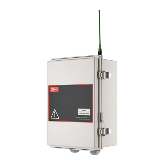
User Manual R70 PLUS Receiver Technical description R70 PLUS dimensions Dimensions in mm 30.50 250.65 External antenna A60 (433) or A70 (870) See next page for receiver board description. © Danfoss | July 2024 BC292467121599en-000201... -
Page 7: Hardware Description
User Manual R70 PLUS Receiver Technical description R70 PLUS hardware description 2. RS232/RS485 socket 3. Power supply 4. INXXX card socket 5. Internal removable EEPROM 6. RF Module 7. CAN connection 8. CAN BUS termination 9. Signaling intern LEDs 10. Wiring connection ©... -
Page 8: Installation
User Manual R70 PLUS Receiver Installation R70 PLUS receiver installation The below information describes hazards to be aware of during installation and steps to locate the receiver. Risk of shock Completely shut down the machine when installing the receiver. Check the power supply and shut off the main switch to disconnect the interface cable between the receiver and the machine's electrical box. -
Page 9: Expansion Cards
The R70 PLUS receiver box can be used when there is not enough space for the expansion cards configuration. The R70 PLUS is set up with the LR13F electronic card and a power supply, if necessary to connect more than two expansion cards. -
Page 10: Internal Wiring
User Manual R70 PLUS Receiver Installation R70 PLUS internal wiring The power cables must be wired and guided form the center of the slot. The rest of the CAN bus wiring can be placed without any restriction. Upper slot Bottom slot... -
Page 11: Recommended Wiring Dimensions
User Manual R70 PLUS Receiver Installation Receiver (continued) Receiver Model Hole Diameter(mm) Recommended Screw Comments 9 mm DIN 7985 M8x25 M6 screw with washer could be used as well MP08, MPCAN 5 mm DIN 7985 M5x25 MP15 5 mm DIN 7985 M5x25... -
Page 12: Troubleshooting
No radio signal detected LED on + transmitter switched Radio channel occupied Change transmitter's frequency channel LED on + DATA switched off Radio channel occupied by non Danfoss system Change transmitter's frequency channel DATA Green; pulsing Receiving good frames LED off + DATA LED on No valid ID;... - Page 13 User Manual R70 PLUS Receiver Troubleshooting Color and frequency Pulse frequency Description Action POWER Green | continuous Switched ON if powered Check power supply if LED is switched off. STATUS Blue | fast pulses System is starting; establishing connection with...
- Page 14 User Manual R70 PLUS Receiver Troubleshooting Color and frequency Pulse frequency Description Action ORDER Green | continuous LED ON Whenever any output is ON RELAY Green | continuous STOP relay activated CANERR Red | slow pulses CAN Error, physical Layer...
- Page 15 Phone: +86 21 2080 6201 Danfoss can accept no responsibility for possible errors in catalogues, brochures and other printed material. Danfoss reserves the right to alter its products without notice. This also applies to products already on order provided that such alterations can be made without subsequent changes being necessary in specifications already agreed.
Need help?
Do you have a question about the R70 PLUS and is the answer not in the manual?
Questions and answers