Table of Contents
Advertisement
Quick Links
Download this manual
See also:
User Manual
Advertisement
Table of Contents

Related Manuals for Danfoss RZ1


Summary of Contents for Danfoss RZ1
-
Page 1: Installation Guide
MAKING MODERN LIVING POSSIBLE Z-Wave Electronic Radio-Frequency Receivers (1-Channel) RZ1 and RZ1-HP Installation Guide Danfoss Heating... - Page 2 For a large print version of these instructions please call Marketing on 0845 121 7400. Danfoss can accept no responsibility for possible errors in catalogues, brochures, and other printed material. All trademarks in this material are property of the respective companies.
-
Page 3: Table Of Contents
Connecting devices to the RZ1 ............8 Disconnecting devices from the RZ1 ..........9 Include devices to network, not using RZ1 relay output .... 9 Exclude devices from network, not using RZ1 relay output ..10 Including the RZ1 as a secondary controller to a network ..10 Excluding the RZ1 as a secondary controller to a network ..11... -
Page 4: Specification
230 Vac, 12 (6) A Switch Rating (Total current) (Total current) IP Rating IP 40 Control Pollution Situation Degree 2 Max. Range 30 metres Operating Frequency 868.42 MHz Software Classification Class A Rated Impulse Voltage 2.5kV Ball Pressure Test 75°C RZ1 AND RZ1-HP... -
Page 5: Mounting Instructions
2.0 Mounting Instructions Danfoss Heating... -
Page 6: Wiring
2.1 Wiring RZ1 ELECTRONICS 1 2 3 4 ZONE ZONE 1 OFF 1 ON Note: For mains voltage applications link terminals L and 2. RZ1 AND RZ1-HP... -
Page 7: Understanding Your Rz1
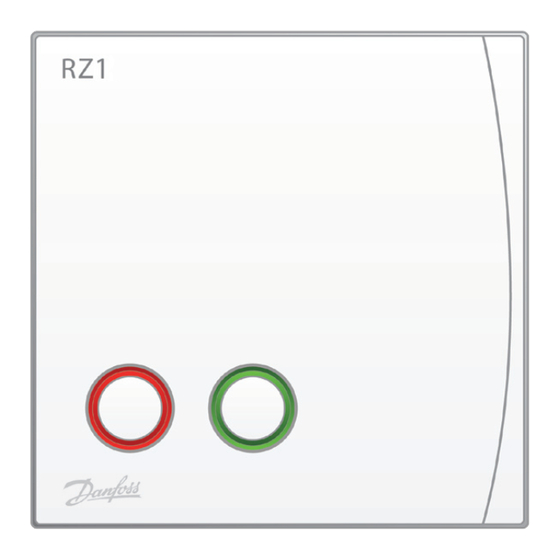
3.0 Understanding your RZ1 The RZ1 receiver unit uses a combination of coloured LEDs to indicate the current operating mode/output status. For the purpose of this document the indicator lights will be split into two distinct groups; CHANNEL LEDs and PROGRAMME LED. More information is listed below together with explanations of each of the LED colour states. -
Page 8: Connecting Devices To The Rz1
RED slowly. Press the ‘include initiator’ button on the wireless device to be connected to the RZ1 (On some devices you may need to press and hold the include initiator button for up to 10 seconds). Once binding has finished the LED for the channel just bound will go out indicating success. -
Page 9: Disconnecting Devices From The Rz1
4.1 Disconnecting devices from the RZ1 Occasionally you may need to remove a thermostat or other Z-Wave device from the RZ1 receiver. To do this, follow the procedure below: Press PROG to set the RZ1 into PROGRAMME mode. Press the button for the associated channel to be un-bound/ disconnected (RED channel LED will flash). -
Page 10: Exclude Devices From Network, Not Using Rz1 Relay Output
If you already have a primary controller in the network and wish to add the RZ1 as a secondary controller, follow the steps below: - Place the RZ1 into programme mode by pressing the PROG button (Programme LED will turn RED) Activate the include/bind initiator on the primary controller in the network. -
Page 11: Excluding The Rz1 As A Secondary Controller To A Network
RED, indicating that it has returned to programme mode. 7. In the event of the RZ1 failing to join an existing network as a secondary controller, the RZ1 will need to have its home and node ID reset back to their default conditions by carrying out a complete system reset by following the process laid out in section 7. -
Page 12: Implementing A Network Controller Shift
5.0 Implementing a network controller shift A network primary controller shift can not be started if: The RZ1/RZ1-HP has created the network and is the existing primary, as it is the networks SIS by default. The RZ1/RZ1-HP is a secondary network controller and not the SUC and no other SIS is in the network. -
Page 13: Initiating A Primary Controller Shift With The Rz1 Being Promoted To The Primary Role
5.2 Initiating a primary controller shift with the RZ1 being promoted to the primary role Should you wish to promote the RZ1 to the role of primary controller in your network, do so by following the same process as for including the RZ1 as a secondary controller in a network (See section 4.4). -
Page 14: Factory Reset
7.0 Factory Reset If for any reason you need to return the RZ1 unit to its factory reset state, or you need to wipe all network information from the unit it is advisable to perform a factory reset. Press PROG to place the receiver in PROGRAMME mode (Red LED illuminated continuously). -
Page 15: Glossary
PROG LED is lit and the device is waiting for instructions to switch on or off its output(s). Reset State In the Reset State the RZ1 is reset back to factory defaults and is ready to either be added into an existing network as a secondary controller or to be used to create a network as a primary controller. - Page 16 Danfoss Randall Ltd. Ampthill Road Bedford MK42 9ER Tel: 0845 1217 400 Fax: 0845 1217 515 Email: danfossrandall@danfoss.com Website: www.danfoss-randall.co.uk Part No. RZ1v04_Installation...
Need help?
Do you have a question about the RZ1 and is the answer not in the manual?
Questions and answers