Advertisement
Quick Links
Advertisement

Subscribe to Our Youtube Channel
Related Manuals for Eaton CW-HMX


Summary of Contents for Eaton CW-HMX
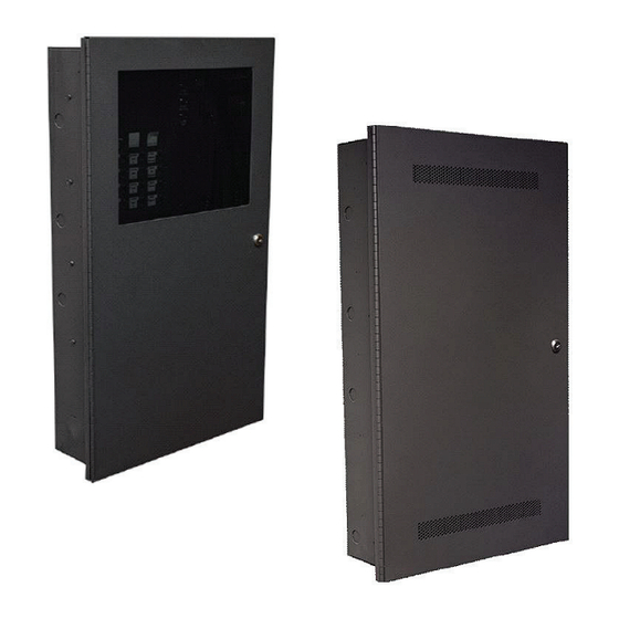
- Page 1 Installation instructions CW-HMX CW-MX-MP Master panel CW- HMX-DP Distribution panel...
-
Page 2: Installation Instructions
Overview - Engineer’s specification Pltast rtad this manual compltttly btfort installing tht CW-HMX systtm. The CW-HMX system shall include one master panel Installation and one or more distributed panels. The system shall be microprocessor based, and shall be compatible for... -
Page 3: Battery Maintenance
‘Power on diagnostics’ program. The green LED will associated with that fire phone zone will start flashing. A remain on to indicate that the CW-HMX system is ringing signal will be heard to indicate that a handset has fully operational and all circuits are nominal. Observe been jacked in. - Page 4 FPL, FPLR, FPLP run in conduit Distributed panel Voice evacuation speaker circuits Master panel Head end control Paging Control Fire CW-EVX-25 CW-EVX-25 Phone CW-EVX-50 CW-EVX-50 CW-EVX-100 CW-EVX-100 Local audio amplifiers Fire phone circuit Fire phone control CW-HMX 25-16566-A August 2019 www.eaton.com...
- Page 5 Field wiring connections: #6-32 wire clamp screw 14-18 AWG #8-32 wire clamp screw 12-18 AWG Horizontal wire entry terminal 18-26 AWG Wire gauge determined by circuit load CW-HMX 25-16566-A August 2019 www.eaton.com...
- Page 6 * 6 flashes typically indicates “External trouble”, such as an CW-EVX-RM. If LED 4 is on, the 6 flash indicates a ground fault. If both a ground fault condition and an external trouble occur simultaneously, the fault codes will not combine for 12 flash. Refer to installation instructions P/N CW-5001 for all amplifier specifications CW-HMX 25-16566-A August 2019 www.eaton.com...
- Page 7 FACP bell circuit - #18 AWG. reading its EOLR. Under any Input control - #24 AWG. fault condition in the CW-HMX ALARM (Must be in the same room within system a contact will open 20 feet of panel, in conduit)
- Page 8 Fire phone - #22 AWG min. Wire gauge determined by circuit load (Max. line res. = 50 Ohms ) 10K 1/2W EOLR Fire phone Fire phone Handset Handset Jack Jack * Maximum line resistance = 50 Ohms CW-HMX 25-16566-A August 2019 www.eaton.com...
- Page 9 Battery standby is current draw from the batteries on loss of power and 28 mA 28 mA otherwise normal standby. 0.2 mA 16 mA Total 225.2 mA 255 mA CW-HMX 25-16566-A August 2019 www.eaton.com...
- Page 10 Eaton EMEA Headquarters Route de la Longeraie 7 1110 Morges, Switzerland Eaton.eu © 2019 Eaton Eaton is a registered trademark. All Rights Reserved Publication No. 25-16566-A All trademarks are property August 2019 of their respective owners.
Need help?
Do you have a question about the CW-HMX and is the answer not in the manual?
Questions and answers