Table of Contents
Advertisement
Quick Links
Advertisement
Table of Contents

Related Manuals for PowMr POW-HVM8.2M


Summary of Contents for PowMr POW-HVM8.2M
- Page 1 User Manual POW-HVM 8.2M & POW-HVM 10.2M...
-
Page 2: Table Of Contents
User Manual POW-HVM8.2M & POW-HVM10.2M Table of Contents 1 ABOUT THIS MANUAL ............................1 1.1 Purpose ..............................1 1.2 Scope ................................. 1 2 SAFETY INSTRUCTIONS ........................... 2 3 INTRODUCTION ..............................3 3.1 Features ..............................3 3.2 Basic System Architecture ........................4 3.3 Product Overview ........................... - Page 3 User Manual POW-HVM8.2M & POW-HVM10.2M 6.11 Warning Indicator ..........................43 7 CLEARANCE AND MAINTENANCE FOR ANTI-DUST KIT ............... 44 7.1 Overview ..............................44 7.2 Clearance and Maintenance ......................44 8 SPECIFICATIONS ............................... 45 8.1 Table 1 Line Mode Specifications ..................... 45 8.2 Table 2 Inverter Mode Specifications ....................
-
Page 4: About This Manual
User Manual POW-HVM8.2M & POW-HVM10.2M 1 ABOUT THIS MANUAL 1.1 Purpose This manual describes the assembly, installation, operation and troubleshooting of this unit. Please read this manual carefully before installations and operations. Keep this manual for future reference. 1.2 Scope... -
Page 5: Safety Instructions
User Manual POW-HVM8.2M & POW-HVM10.2M 2 SAFETY INSTRUCTIONS WARNING: This chapter contains important safety and operating instructions. Read and keep this manual for future reference. 1. Before using the unit, read all instructions and cautionary markings on the unit, the batteries and all appropriate sections of this manual. -
Page 6: Introduction
User Manual POW-HVM8.2M & POW-HVM10.2M 3 INTRODUCTION This is a multi-function inverter/charger, combining functions of inverter, solar charger and battery charger to offer uninterruptible power support with portable size. Its comprehensive LCD display offers user-configurable and easy-accessible button operation such as battery charging current, AC/solar charger priority, and acceptable input voltage based on different applications. -
Page 7: Basic System Architecture
User Manual POW-HVM8.2M & POW-HVM10.2M 3.2 Basic System Architecture The following illustration shows basic application for this inverter/charger. It also includes following devices to have a complete running system: ⚫ Generator or Utility ⚫ PV modules Consult with your system integrator for other possible system architectures depending on your requirements. -
Page 8: Product Overview
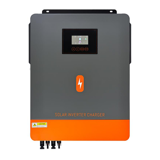
User Manual POW-HVM8.2M & POW-HVM10.2M 3.3 Product Overview LCD display Status indicator Charging indicator Touch Function Fault indicator Power on/off switch buttons AC input Main output Second output WiFi Battery PVI and PV2 input communication/RS- communication/RS- 232 port 485 port... -
Page 9: Installation
User Manual POW-HVM8.2M & POW-HVM10.2M 4 INSTALLATION 4.1 Unpacking and Inspection Before installation, please inspect the unit. Be sure that nothing inside the package is damaged. You should have received the following items inside of package: ⚫ The unit x 1 ⚫... -
Page 10: Connection
User Manual POW-HVM8.2M & POW-HVM10.2M 5 Connection 5.1 Battery Connection Recommended battery cable size: Model Wire Size Cable(mm²) Torque value (max) 8.2KW/10.2KW 1 x 2AWG 2 Nm CAUTION ⚫ For safety operation and regulation compliance, it's requested to install a separate DC over- current protector or disconnect device between battery and inverter. - Page 11 User Manual POW-HVM8.2M & POW-HVM10.2M 4. Insert the battery wires flatly into battery connectors of inverter and make sure the bolts are tightened with torque of 2 Nm in clockwise direction. Make sure polarity at both the battery and the inverter/charge is correctly connected and conductors are tightly screwed into the battery terminals.
-
Page 12: Ac Input/Output Connection
User Manual POW-HVM8.2M & POW-HVM10.2M 5.2 AC Input/Output Connection Suggested cable requirement for AC wires Model Gauge Cable(mm²) Torque value (max) 8.2KW/10.2KW 10 AWG 1.2 Nm CAUTION ⚫ Before connecting to AC input power source, please install a separate AC breaker between inverter and AC input power source. - Page 13 User Manual POW-HVM8.2M & POW-HVM10.2M WARNING ⚫ Be sure that AC power source is disconnected before attempting to hardwire it to the unit. 4. Then, insert AC output wires according to polarities indicated on terminal block and tighten terminal screws.
-
Page 14: Pv Connection
User Manual POW-HVM8.2M & POW-HVM10.2M 5.3 PV Connection Model Wire Size Cable(mm²) Torque value (max) 8.2KW/10.2KW 1 x 10AWG 1.2 Nm CAUTION ⚫ Before connecting to PV modules, please install separately a DC circuit breaker between inverter and PV modules. - Page 15 User Manual POW-HVM8.2M & POW-HVM10.2M PV Module Wire Connection Step 1. Check the input voltage of PV array modules, The acceptable input voltage of the inverter is 120VDC-500VDC. Please make sure that the maximum current load of each PV input...
-
Page 16: Final Assembly
User Manual POW-HVM8.2M & POW-HVM10.2M Insert striped cable into female terminal and crimp female terminal as shown below charts. Insert assembled cable into female connector housing as shown below charts. Insert striped cable into male terminal and crimp male terminal as shown below charts. -
Page 17: Communication Connection
User Manual POW-HVM8.2M & POW-HVM10.2M 5.5 Communication Connection 1. Wi-Fi cloud communication (option): Please use supplied communication cable to connect to inverter and Wi-Fi module. Download APP and installed from APP store, and Refer to "Wi-Fi Plug Quick Installation Guideline" to set up network and registering. - Page 18 User Manual POW-HVM8.2M & POW-HVM10.2M Connection Method: RJ45 connected to A-01 A-02 the BMS port of the inverter. RJ45 connected to the RS485 port of EMPTY PIN IS NOT CONNECTED the lithium battery. The interface for the lithium battery communication cable is shown in the figure.
-
Page 19: Operation
User Manual POW-HVM8.2M & POW-HVM10.2M 6 OPERATION 6.1 Power ON/OFF Side view of unit Once the unit has been properly installed and the batteries are connected well, simply press On/Off switch (located on the button of the case) to turn on the unit. - Page 20 User Manual POW-HVM8.2M & POW-HVM10.2M ➢ Function Keys Function Key Description To exit setting mode To go to previous selection DOWN To go to next selection ENTER To confirm the selection in setting mode or enter setting mode ➢ LED Indicator...
-
Page 21: Lcd Display Icons
User Manual POW-HVM8.2M & POW-HVM10.2M 6.3 LCD Display Icons Icon Function description Input Source Information Indicates the AC input. Indicates the PV input Indicate input voltage, input frequency, PV voltage, charger current (if PV in charging for 10.2KW models), charger power, battery voltage. - Page 22 User Manual POW-HVM8.2M & POW-HVM10.2M Battery Information Load Information Indicates overload. Mode Operation Information Indicates unit connects to the mains. Indicates unit connects to the PV panel. Indicates load is supplied by utility power. Indicates the utility charger circuit is working.
-
Page 23: Lcd Setting
User Manual POW-HVM8.2M & POW-HVM10.2M 6.4 LCD Setting After pressing and holding ENTER button for 3 seconds, the unit will enter setting mode. Press "UP" or "DOWN" button to select setting programs. And then, press "ENTER" button to confirm the selection or ESC button to exit. - Page 24 User Manual POW-HVM8.2M & POW-HVM10.2M Utility provides power to the loads only when battery voltage drops to either low-level warning voltage or the setting point in program 12. Solar energy provides power to the loads as first priority if solar energy is not sufficient to...
- Page 25 User Manual POW-HVM8.2M & POW-HVM10.2M When the solar energy exists, Set User-Defined this item to LIB, and the Lithium battery will be activated for 3 second. If selected, it will enable lithium battery communication for the User-Defined PACE 232 BMS. The lithium battery activation function will be automatically enabled.
- Page 26 User Manual POW-HVM8.2M & POW-HVM10.2M Maximum utility charging Current Note: If setting value in 80A(default) program 02 is smaller Setting range is 2A and 10~140A. than that in program in Increment of each click is 10A. 11, the inverter will...
- Page 27 User Manual POW-HVM8.2M & POW-HVM10.2M "LIP" or "LIL" is selected in Program 05. Setting range:10%~100% Increment of each click is 5%. When the battery charge is 60%(default) above the set value, it will automatically switch back to battery mode output (when the...
- Page 28 User Manual POW-HVM8.2M & POW-HVM10.2M If selected, no matter how users Return to default switch display screen, it will display screen automatically return to default (default) display screen (Input voltage Auto return to default /output voltage) after no button display screen is pressed for 1 minute.
- Page 29 User Manual POW-HVM8.2M & POW-HVM10.2M If self-defined is selected in program 5, this program can be set up. Setting range is from 48.0V to 61.0V for 8.2KW/10.2KW model. Increment of each click is 0.1V. 8.2KW/10.2KW default setting: 40.0V If self-defined is selected in program 5, this program can Low DC cut-off voltage be set up.
- Page 30 User Manual POW-HVM8.2M & POW-HVM10.2M Enable Disable (default) If equalization function is enabled in program 30, this Equalization activated program can be set up. If "Enable" is selected in this immediately program, it's to activate battery equalization immediately and LCD main page will shows“...
- Page 31 User Manual POW-HVM8.2M & POW-HVM10.2M 8.2KW/10.2KW default setting: 55% Exit the dual output Setting range is from 5% to 85% for 48VDC model. functional load Increment of each click is 5%. percentage When the power drops below the set value, the inverter main output is disconnected, and the main output no longer supplies power to external loads.
-
Page 32: Display Setting
User Manual POW-HVM8.2M & POW-HVM10.2M 6.5 Display Setting The LCD display information will be switched in turns by pressing "UP" or "DOWN" key. The selectable information is switched as below order: input voltage, input frequency, PV voltage, charging current, charging power, battery voltage, output voltage, output frequency, load percentage, load in Watt, load in VA, load in Watt, DC discharging current, main CPU Version. - Page 33 User Manual POW-HVM8.2M & POW-HVM10.2M Charged state, and the power is greater than 1 kw Input voltage=222V, PV voltage=168V, Battery voltage= 25V, Output voltage=222V, Load in Watt=1.18KW, Chg(Flashing), Inv/ac(bright) Input voltage=224V, PV current=8.6A, Battery current=12.5A, Output voltage=222V, Load in VA=1.88KVA,...
- Page 34 User Manual POW-HVM8.2M & POW-HVM10.2M Input voltage=0V, PV current=0A, Battery current=12.5A, Output voltage=222V, Load in VA=188VA, Chg(turn off), Inv/ac(Flashing) Input voltage=0V, Pv ntc temperture=60.0℃, Battery voltage= 24V, Inv ntc temperture=36.0℃, Load percentage=13%, Chg(turn off), Inv/ac(Flashing) Input frequency=0Hz, PV power=0KWh, Battery current=12A, Output frequency=50.0Hz,...
- Page 35 User Manual POW-HVM8.2M & POW-HVM10.2M Input frequency=0Hz, PV power=0KWh, Battery current=111A, Output frequency=50.0Hz, Load in watt=1.21KW, Chg(turn off), Inv/ac(Flashing) Main CPU version 21 05 Main CPU version checking...
-
Page 36: Operating Mode Description
User Manual POW-HVM8.2M & POW-HVM10.2M 6.6 Operating Mode Description Operation Selectable information LCD display mode Input voltage=222V, PV voltage=210V, Battery voltage=25V, Output voltage=0V, Load in Watt=0W, Chg(FIashing), Inv/ac(bright) Input voltage=223V PV voltage=0V, Battery voltage=25V, Stanby mode Output voltage=0V, Load in Watt=0W,... - Page 37 User Manual POW-HVM8.2M & POW-HVM10.2M Input voltage=224V, PV voltage=0V, Battery voltage= 25V, Output voltage=222V, Load in Watt=188W, Chg(FIashing), Inv/ac(bright) Input voltage=224V, PV current=8.6A, Grid-Tie Battery current=25A, Operation Output voltage=222V, Load in VA=1.88KVA, When working in Grid-Tie mode, the Grid Chg(Flashing), Inv/ac(bright) will be flash 3S/times.
- Page 38 User Manual POW-HVM8.2M & POW-HVM10.2M Selectable information LCD display LIC(Lithium battery communication connection PACE 232 BMS ) Total battery voltage=52.4V Battery residual capacity=23% Battery charging current=0A Battery discharge current=1A Nominal battery voltage=48V Total battery capacity=100AH Battery remaining capacity=23% Battery charger/discharge Times=8 Battery ambient temperature=28.2℃...
- Page 39 User Manual POW-HVM8.2M & POW-HVM10.2M Single battery voltage=3.27V Single battery temperature=28.5℃ LIP Mode Lithium Battery Display Interface Detailed Explanation (PACE485 BMS) Data displayed in the top- Data displayed in the top- right corner of the LCD LCD Screen Interface left corner of the LCD screen...
- Page 40 User Manual POW-HVM8.2M & POW-HVM10.2M Single Cell Maximum Voltage Single Cell Minimum Voltage = 3.33V = 3.33V Maximum Battery Minimum Battery Temperature = 24.8°C Temperature = 24.9°C LIL Mode Lithium Battery Display Interface Detailed Explanation (Pylon 485 BMS) Data displayed in the top-...
-
Page 41: Rgb Light (Option )
User Manual POW-HVM8.2M & POW-HVM10.2M Single Cell Maximum Voltage Single Cell Minimum Voltage = 3.33V = 3.33V Maximum Battery Minimum Battery Temperature = 24.8°C Temperature = 24.9°C Minimum MOS Temperature = Maximum MOS Temperature 24.3°C = 24.2°C 6.7 RGB Light (option ) ⚫... -
Page 42: Battery Equalization Description
User Manual POW-HVM8.2M & POW-HVM10.2M 6.8 Battery Equalization Description Equalization function is added into charge controller. It reverses the buildup of negative chemical effects like stratification, a condition where acid concentration is greater at the bottom of the battery than at the top. Equalization also helps to remove sulfate crystals that might have built up on the plates. -
Page 43: Utility Power And Lithium Battery Activation Function
User Manual POW-HVM8.2M & POW-HVM10.2M However, in Equalize stage, when battery equalized time is expired and battery voltage doesn't rise to battery equalization voltage point, the charge controller will extend the battery equalized time until battery voltage achieves battery equalization voltage. If battery voltage is still lower than battery equalization voltage when battery equalized timeout setting is over, the charge controller will stop equalization and return to float stage. -
Page 44: Fault Reference Code
User Manual POW-HVM8.2M & POW-HVM10.2M 6.10 Fault Reference Code Fault Code Fault Event Icon on Fan is locked when inverter is off. Over temperature Battery voltage is too high Battery voltage is too low Output short circuited or over temperature is detected by internal converter components. - Page 45 User Manual POW-HVM8.2M & POW-HVM10.2M Current sensor failed Output voltage is too low PV voltage is over limitation Add Battery Fault Codes in Lithium Battery Mode Fault Code Fault Event Fault Status Lithium battery charging temperature > 65°C Battery Temperature Too High Lithium battery discharge temperature >...
-
Page 46: Warning Indicator
User Manual POW-HVM8.2M & POW-HVM10.2M 6.11 Warning Indicator Warning Code Warning Event Audible Alarm Icon flashing Fan is locked when Beep three times every inverter is on. second Battery is over-charged Beep once every second Low battery Beep once every second Overload Beep once every 0.5 second... -
Page 47: Clearance And Maintenance For Anti-Dust Kit
User Manual POW-HVM8.2M & POW-HVM10.2M 7 CLEARANCE AND MAINTENANCE FOR ANTI-DUST KIT 7.1 Overview Every inverter is already installed with anti-dusk kit from factory. Inverter will automatically detect this kit and activate internal thermal sensor to adjust internal temperature. This kit also keeps dusk from your inverter and increases product reliability in harsh environment. -
Page 48: Specifications
User Manual POW-HVM8.2M & POW-HVM10.2M 8 SPECIFICATIONS 8.1 Table 1 Line Mode Specifications INVERTER MODEL 8.2KW 10.2KW Input Voltage Waveform Sinusoidal (utility or generator) Nominal Input Voltage 230Vac Low Loss Voltage 170Vac±7V (UPS); 90Vac±7V (Appliances) Low Loss Return Voltage 180Vac±7V (UPS);100Vac±7V (Appliances) High Loss Voltage 280Vac±7V... - Page 49 User Manual POW-HVM8.2M & POW-HVM10.2M 8.2 Table 2 Inverter Mode Specifications INVERTER MODEL 8.2KW 10.2KW Rated Output Power 8.2KW 10.2KW Output Voltage Waveform Pure Sine Wave Output Voltage Regulation 230Vac±5% Output Frequency 50Hz Peak Efficiency Overload Protection 3s@≥150%load; 5s@101%150% load...
- Page 50 User Manual POW-HVM8.2M & POW-HVM10.2M 8.4 Table 4 Charge Mode Specifications Utility Charging Mode INVERTER MODEL 8.2KW 10.2KW Charging Algorithm 3-Step AC Charging Current (Max) 140Amp 140Amp Bulk 58.4 Flooded Battery Charging 56.4 AGM / Gel Battery Voltage Floating Charging Voltage...
- Page 51 User Manual POW-HVM8.2M & POW-HVM10.2M 8.5 Table 5 Grid-Tie Operation INVERTER MODEL 8.2KW 10.2KW Nominal Output Voltage 220/230/240VAC Feed-in Grid Voltage Range 195~253VAC Feed-in Grid Frequency Range 49~51±1Hz/59~61±1Hz Nominal Output Current 35.6A 44.3A Power Factor Range >0.99 Maximum Conversion Efficiency (DC/AC) 8.6 Table 6 General Specifications...
-
Page 52: Trouble Shooting
User Manual POW-HVM8.2M & POW-HVM10.2M 9 TROUBLE SHOOTING Explanation /Possible Problem LCD/LED/Buzzer What to do cause LCD/LEDs and Unit shuts down buzzer will be automatically The battery voltage is too 1. Re-charge battery. active for 3 during startup low (<1.91V/CeIl) 2. - Page 53 User Manual POW-HVM8.2M & POW-HVM10.2M and red LED is Check if wiring is Output short circuited. connected well and remove abnormal load. Fault code 05 Temperature of internal Check whether the air converter component is flow of the unit is over 120℃.
-
Page 54: Appendix: Approximate Back-Up Time Table
User Manual POW-HVM8.2M & POW-HVM10.2M 10 Appendix: Approximate Back-up Time Table Backup Time @ 48Vdc 100Ah Backup Time @ 48Vdc 200Ah Model Load (W) (min) (min) 1288 1000 1500 2000 2500 3200 3500 8.2KW 4000 10.2KW 4500 5000 6200 7200... - Page 55 User Manual POW-HVM8.2M & POW-HVM10.2M...
Need help?
Do you have a question about the POW-HVM8.2M and is the answer not in the manual?
Questions and answers