Table of Contents
Advertisement
Quick Links
Advertisement
Table of Contents

Related Manuals for PowMr POW-LTW-15A


Summary of Contents for PowMr POW-LTW-15A
- Page 1 User Manual POW-LTW-15A...
-
Page 2: Important Safety Guidelines
User Manual POW-LTW-15A Important Safety Guidelines Warning: Please carefully read and adhere to all safety instructions. ➢ Before installing and operating the controller, carefully read the user manual and keep it stored safely for future reference. ➢ Installation or operation of the controller is not permitted for the following individuals without strict guidance and supervision: a. - Page 3 User Manual POW-LTW-15A e. Ensure the equipment is set up reasonably according to the connected battery type. DC Battery Wiring a. Ensure all cables and/or new ports connecting to the battery/DC system are fully closed/disconnected in advance. b. Use flexible multi-strand copper cables with appropriate cross-sectional areas and connect them to matching fuses or circuit breakers.
- Page 4 User Manual POW-LTW-15A Disclaimer In any of the following circumstances, our company reserves the right to disclaim liability for quality assurance: ⚫ Damage caused by improper transportation. ⚫ Damage resulting from incorrect storage, installation, or usage. ⚫ Damage caused by non-professionals or untrained personnel installing and using the equipment.
-
Page 5: Table Of Contents
User Manual POW-LTW-15A Table of Contents Important Safety Guidelines ..........................1 1 Product Introduction ............................4 1.1 Features ..............................5 1.2 Product Appearance ..........................7 2 Installation and Wiring ............................8 2.1 Unboxing and Inspection ........................8 2.2 Selecting Installation Location ......................8 2.3 Wiring Precautions .......................... -
Page 6: Product Introduction
By choosing the POW-LTW-15A Solar Controller, you will gain an efficient, sustainable, and secure energy management solution, providing solid support for future energy needs. We are committed to driving the development of solar technology, and delivering exceptional products and services to you. -
Page 7: Features
User Manual POW-LTW-15A 1.1 Features ⚫ Compact Size, Lightweight The controller features a compact internal structure design and precise internal components, reducing the overall size and weight, enhancing its flexibility for various scenarios. ⚫ Integrated Charging Presets Integrated charging modes, including adaptive charging logic, are highly suitable for most battery types, such as flooded lead-acid batteries, gel sealed lead-acid batteries, and lithium batteries. - Page 8 User Manual POW-LTW-15A ⚫ Adaptive Boost Charging During initial charging, adaptive boost charging monitors battery response and automatically determines the duration of the boost stage that corresponds to each independent charging cycle. This ensures the battery is fully charged at any discharge level or capacity, avoiding timeouts during the boost charging stage (extends battery life).
-
Page 9: Product Appearance
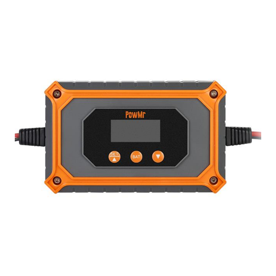
User Manual POW-LTW-15A 1.2 Product Appearance LCD Display Screen Photovoltaic Input Interface Function Buttons Battery Interface... -
Page 10: Installation And Wiring
User Manual POW-LTW-15A 2 Installation and Wiring 2.1 Unboxing and Inspection Before unboxing, check if the packaging is damaged. After unboxing, inspect the contents for any damage or missing items. Inside the package, you will find: ⚫ Controller ⚫ User Manual ⚫... -
Page 11: Wiring Precautions
User Manual POW-LTW-15A 2.3 Wiring Precautions 1. Follow the sequence below for wiring: Battery > Photovoltaic Input. 2. Loose connections can cause cables or terminals to overheat, so ensure all cables are tightened to limit transition resistance as much as possible. Use cables of appropriate size according to the current rating of the specific circuit. - Page 12 User Manual POW-LTW-15A Step 3. Connect the photovoltaic array. Connect the photovoltaic array to the controller's built- in MC4 connector to access the photovoltaic input power. NOTE ⚫ Follow the wiring sequence: Battery > Photovoltaic Input. Incorrect wiring sequence may cause irreversible damage to the controller.
-
Page 13: Operation Guide
User Manual POW-LTW-15A 3 Operation Guide 3.1 Button Introduction Button Function Short Press Enter the next page. Browse Mode Long Press Enter settings. SET/▲ Short Press Navigate to the next option/increase value. Setting Mode Long Press Confirm the option. Short Press Enter battery type settings/confirm and save battery type. -
Page 14: Interface Icon Explanation
User Manual POW-LTW-15A 3.2 Interface Icon Explanation Icon Description Sealed Lead-Acid Battery Gel Sealed Lead-Acid Battery 4-Cell Lithium Iron Phosphate Battery 8-Cell Lithium Iron Phosphate Battery Custom Battery Type Current Photovoltaic Input Present No Current Photovoltaic Input Detected Battery Level 1. -
Page 15: Display
User Manual POW-LTW-15A 3.3 Display Page Overview Use the ▲ or ▼ buttons to toggle through the display screens. The contents of each screen are as follows: Current Battery PV Input Charging Current Voltage Wattage Device Calibration Voltage System Voltage... -
Page 16: Setting Guide
User Manual POW-LTW-15A 3.4 Setting Guide Battery Type Setting Icon Battery Type Sealed Lead-Acid Battery Gel Sealed Lead-Acid Battery 4-Cell Lithium Iron Phosphate Battery 8-Cell Lithium Iron Phosphate Battery User Defined 1. After completing the connection and successfully starting the controller, long-press the BATT button to enter the battery type setting interface. - Page 17 User Manual POW-LTW-15A System Voltage Setting Interface System voltage options: 12V/24V. Boost Charging Voltage Setting Interface Default: 14.4V, setting range: 9.0~17.0V, step: 0.1V. Float Charging Voltage Setting Interface Default: 13.8V, setting range: 9.0~17.0V, step: 0.1V. Float Charging Voltage Setting Interface Default: 13.2V, setting range: 9.0~17.0V, step: 0.1V.
-
Page 18: Default Charging Parameters For Different Battery Types
User Manual POW-LTW-15A 3.5 Default Charging Parameters for Different Battery Types Battery Type Parameters Boost Charging Voltage 14.4V 14.2V 14.4V 28.8V 9.0~17.0V Float Charging Voltage 13.8V 13.8V 14.0V 28.0V 9.0~17.0V MPP Tracking Return Voltage 13.2V 13.2V 13.2V 26.4V 9.0~17.0V NOTE ⚫... - Page 19 User Manual POW-LTW-15A ⚫ Lithium Battery Charging Two Stages: Voltage Boost Charging Voltage MPPT Tracking Return Voltage Current Time Time Boost Bulk Charging Charging Stage Stage...
-
Page 20: Protection
User Manual POW-LTW-15A 4 Protection 4.1 Protection Functions Protection Description When a short circuit occurs in the photovoltaic array, the controller will Photovoltaic Array cease charging. Once the short circuit fault is rectified, normal Short Circuit operation can resume. The controller limits the battery charging current to the maximum Photovoltaic Input rated battery current. -
Page 21: Troubleshooting
User Manual POW-LTW-15A 4.2 Troubleshooting Fault Code Display Example - E71 Fault Codes Description Explanation/Resolution When the temperature exceeds 85°C, the device triggers Overtemperature an alarm and stops charging. Once the temperature Protection drops below 75°C, the alarm is cleared, and charging resumes. -
Page 22: Maintenance
User Manual POW-LTW-15A 5 Maintenance It is recommended to perform the following checks and maintenance tasks at least twice a year to ensure optimal operation: 1. Ensure the controller is securely installed in a clean and dry environment. 2. Ensure proper airflow around the controller and clean any dust or debris from the heat sink. -
Page 23: Specifications
User Manual POW-LTW-15A 6 Specifications Model POW-LTW-15A Photovoltaic Input Parameters Max. Open Circuit Voltage of PV Array 12V System 24V System Maximum Input Power: 12V System 180W 24V System 360W Input Voltage Range: 12V System <30V 24V System <60V Battery Charging Parameters... - Page 24 User Manual POW-LTW-15A...
Need help?
Do you have a question about the POW-LTW-15A and is the answer not in the manual?
Questions and answers