Table of Contents
Advertisement
Advertisement
Table of Contents

Related Manuals for PowMr POW-LVM3.2K-24V


Summary of Contents for PowMr POW-LVM3.2K-24V
- Page 2 Important safety instructions Please keep this manual for future use. This manual contains all safety, installation and operating instructions for the POW-LVM3.2K-24V solar storage inverter. Please read all instructions and precautions in the manual carefully before installation and use. Non-safety voltage exists inside the solar storage inverter. To avoid personal injury, users shall not disassemble the solar storage inverter themselves.
-
Page 3: Table Of Contents
CONTENTS 1. GENERAL INFORMATION ............................4 1.1 P ..........................4 RODUCT OVERVIEW AND FEATURES 1.2 B ............................5 ASIC SYSTEM INTRODUCTION 1.3 A ..................................7 PPEARANCE 1.4 D ..............................8 IMENSION DRAWING 2. INSTALLATION INSTRUCTIONS ......................... 9 2.1 I ............................9 NSTALLATION PRECAUTIONS 2.2 W .................. -
Page 4: General Information
1. General information 1.1 Product overview and features POW-LVM3.2K-24V is a new solar storage inverter, which integrates solar energy storage & mains charging energy storage and AC sine wave output. Thanks to DSP control and advanced control algorithm, it has high response speed, high reliability and high industrial standard. -
Page 5: Basic System Introduction
4. Advanced MPPT technology with an efficiency of 99.9%. 5. Designed with a LCD screen and 3 LED indicators for dynamic display of system data and operating status. 6. ON/OFF rocker switch for AC output control. 7. Power saving mode available to reduce no-load loss. 8. -
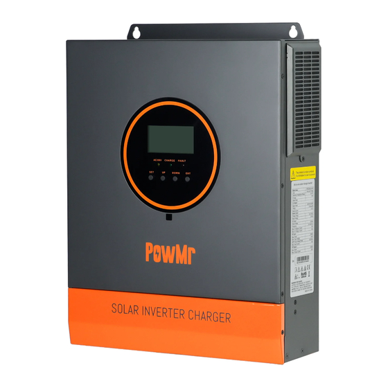
Page 7: Appearance
1.3 Appearance ① ⑧ AC input terminal Cooling fan ② ⑨ AC output terminal Battery input terminal ③ ⑩ USB communication port ON/OFF rocker switch RS485/WIFI communication ④ ⑪ PV input terminal port ⑤ ⑫ Dry contact port Touchable buttons ⑥... -
Page 8: Dimension Drawing
1.4 Dimension drawing... -
Page 9: Installation Instructions
2. Installation instructions 2.1 Installation precautions Please read this manual carefully prior to installation to familiarize yourself with the installation steps. Be very careful when installing the battery. Wear safety goggles when installing a lead-acid liquid battery. Once coming into contact with the battery acid, rinse with clean water timely. Do not place metal objects near the battery to prevent short-circuit of the battery. -
Page 10: Wiring Specifications And Circuit Breaker Selection
2.2 Wiring specifications and circuit breaker selection Wiring and installation must comply with national and local electrical codes. Recommended PV array wiring specifications and circuit breaker selection: Since the output current of the PV array is affected by the type, connection method and illumination angle of the PV module, the minimum wire diameter of the PV array is calculated according to its short-circuit current;... - Page 11 Recommended battery input wire diameter and switch selection: Recommended Maximum Recommended air Rated battery Models battery wiring charge switch or circuit discharge current diameter current breaker type POW- 30mm /2AWG LVM3.2K- 140A 100A 2P—160A Recommended AC output wiring specifications and circuit breaker selection: ...
-
Page 12: Installation And Wiring
2.3 Installation and wiring Installation steps:: Step 1: Determine the installation position and the space for heat dissipation. Determine the installation position of the solar storage inverter, such as wall surface; when installing the solar storage inverter, ensure that there is enough air flowing through the heat sink, and space of at least 200m to the left and right air outlets of the inverter shall be left to ensure natural convection heat dissipation. - Page 13 Step 2: Remove the terminal cover Step3: Wiring AC input / output wiring method: ① Prior to AC input/output wiring, disconnect the external circuit breaker and confirm that the wire used is thick enough. Please refer to Section 2.2 “Wiring Specifications and Circuit Breaker Selection”;...
- Page 14 :Ground L:Live N:Neutral ③ Properly connect the AC output wire according to the wire sequence and terminal position shown in the figure below. Please connect the ground wire first, and then the live wire and the neutral wire. The ground wire is connected to the grounding screw hole on the cabinet through the O-type terminal.
- Page 15 PV input wiring method: ① Prior to wiring, disconnect the external circuit breaker and confirm that the wire used is thick enough. Please refer to Section 2.2 “ Wiring Specifications and Circuit Breaker Selection”; ② Properly connect the PV input wire according to the wire sequence and terminal position shown in the figure below.
- Page 16 BAT+: Battery positive BAT-: Battery negative Warnings: ① Mains input, AC output and PV array will generate high voltage. So, before wiring, be sure to disconnect the circuit breaker or fuse; ② Be very careful during wiring; do not close the circuit breaker or fuse during wiring, and ensure that the “+”...
- Page 17 Step 5: Install the terminal cover. Step 6: Turn on the solar storage inverter First, close the circuit breaker at the battery terminal, and then turn the rocker switch on the left side of the machine to the "ON" state. The "AC/INV" indicator flashing indicates that the inverter is working normally.
-
Page 18: Operating Modes
3. Operating modes 3.1 Charging mode 1) PV priority: PV module will charge the battery preferentially, and the battery is charged by the Mains only when the PV system fails. During the day, solar energy is fully used to charge, while at night, it converts to the Mains. -
Page 19: Output Mode
3.2 Output mode PV priority mode: When photovoltaic is ineffective, it switches to mains power and charging. This mode maximises the use of solar energy while maintaining battery power, and is suitable for areas with relatively stable power grids. PV failure PV recover Mains priority mode:... -
Page 20: Lcd Screen Operating Instructions
4. LCD screen operating instructions 4.1 Operation and display panel The operation and display panel is as shown below, including 1 LCD screen, 3 indicators and 4 operation buttons. Operation buttons introduction Function buttons Description Enter/Exit Settings menu Previous choice DOWN Next choice Confirm/Enter Options under the settings menu... - Page 21 LCD screen introduction Icons Functions Icons Functions Indicates that the AC input Indicates that the inverter circuit is terminal has been connected to working the grid Indicates that the AC input mode Indicates that the machine is in the in APL mode (wide voltage range) Mains Bypass mode Indicates that the PV input terminal Indicates that the AC output is in an...
- Page 22 type of the machine is a lead-acid alarm battery Indicates that the battery is in Indicates that the machine is in a charging state fault condition Indicates that the AC/PV charging Indicates that the machine is in circuit is working setup mode The parameters displayed in the middle of the screen:...
- Page 23 Real-time data viewing method On the LCD main screen, press the “UP” and “DOWN” buttons to scroll through the real-time data of the machine. Parameters Parameters on the left side of the in the Parameters on the right side Page screen middle of of the screen...
-
Page 24: Setup Parameters Description
4.2 Setup parameters description Buttons operation instructions: Press the “ SET ” button to enter the setup menu and exit the setup menu. After entering the setup menu, the parameter number [00] will flash. At this point, press the “ UP ” and “ DOWN ” buttons to select the code of parameter item to be set. Then, press the “... - Page 25 Name Options Description Parameter [01] = SOL/SBU, the battery voltage is lower than this setting value, the output is Battery to [04] 23V switched from inverter to mains, the setting mains default range is 20V~27V. It can not be set higher than the value of [14] setting item.
- Page 26 Name Options Description Flooded lead-acid battery, constant voltage [08] FLd charging voltage is 29.2V, float charging voltage is 27.6V. [08] GEL Gel lead-acid battery, constant voltage charging default voltage is 28.4V, float charging voltage is 27.6V. LF07/LF08/LF09 lithium iron phosphate batteries, corresponding to lithium iron phosphate batteries 7-series, 8-series and 9-series.
- Page 27 Name Options Description Over-discharge voltage, the battery voltage is lower than this judgement point, delay the time Over- [12] 21V set by parameter [13], and then shut down the discharge default inverter output. Setting range 20V~28V, step of voltage 0.2 V. Valid when battery type is user-defined and lithium battery.
- Page 28 Name Options Description Equalized charging time, setting range Equalize [18] 120 5min~900min, step of 5 minutes. Valid when charging time default battery type is flooded lead-acid battery and sealed lead-acid battery. Equalized charging delay, setting range Equalize [19] 240 5min~900min, step of 5 minutes. Valid when charging delay default battery type is flooded lead-acid battery and...
- Page 29 Name Options Description Disable automatic restart in case of over- temperature, if over-temperature occurs to shut [24] DIS down the output the machine will no longer Automatic switch on the output. over- temperature Enable automatic over-temperature restart, if restart [24] ENA over-temperature occurs to shut down the default output, it will restart to switch on the output...
- Page 30 When [32] = 485, the protocol are: PAC=PACE,RDA=RITAR, n protocols AOG=ALLGRAND BATTERY,OLT=OLITER, XWD=SUNWODA, DAQ=DYNESS, WOW=SRNE, PYL=PYLONTECH,SHO=FOX ESS, POW=POWMR Battery under- When the battery is under-voltage, the battery [35] 26V voltage voltage needs to be greater than this setting to...
-
Page 31: Battery Type Parameters
4.3 Battery type parameters For Lead-acid Battery : Battery type Sealed lead Gel lead-acid Flooded lead User-defined acid battery battery acid battery Adjustable (User) Parameters (GEL) (FLD) (SLD) Overvoltage disconnection voltage Battery fully charged recovery point(setup 18~30V √ item [37]) Equalizing charge √... - Page 32 For Lithium Battery : Battery type Ternary Ternary LFP(LF07) LFP(LF08) LFP(LF09) Adjustable (N07) (N08) Parameters Overvoltage 31.6V 33.0V disconnection voltage Battery fully charged recovery point(setup √ 27.4V 30.4V 23.2V 26.8V 29.8V item [37]) Equalizing charge voltage √ Boost charge voltage 28.8V 31.6V 24.6V...
-
Page 33: Other Functions
5. Other functions 5.1 Dry contact Working principle: This dry node can control the ON/OFF of the diesel generator to charge the battery. ① Normally, the terminals are that the NC-N point is closed and the NO-N point is open; ② When the battery voltage reaches the low voltage disconnection point, the relay coil is energized, and the terminals turn to that the NO-N point is closed while NC-N point is open. -
Page 34: Protection
6. Protection 6.1 Protective function Protections Description PV current/power When charging current or power of the PV array configured exceeds limiting the PV rated, it will charge at the rated. protection PV night reverse- At night, the battery is prevented from discharging through the PV current module because the battery voltage is greater than the voltage of PV protection... - Page 35 PV reverse polarity When the PV polarity is reversed, the machine will not be damaged. protection AC reverse Prevent battery inverter AC current from being reversely input to protection bypass. Bypass over current Built-in AC input overcurrent protection circuit breaker. protection Battery input When the discharge output current of the battery is greater than the...
-
Page 36: Fault Code
6.2 Fault code Whether it affects the Fault code Fault name Description output or not BatVoltLow Battery undervoltage alarm 【01】 Battery discharge average current BatOverCurrSw 【02】 overcurrent software protection BatOpen Battery not-connected alarm 【03】 BatLowEod Battery undervoltage stop discharge alarm 【04】... - Page 37 【16】 InvShort Inverter short circuit protection 【17】 【18】 OverTemperMppt Buck heat sink over temperature protection 【19】 Inverter heat sink over temperature OverTemperInv 【20】 protection FanFail Fan failure 【21】 EEPROM Memory failure 【22】 ModelNumErr Model setting error 【23】 【24】 【25】 Inverted AC output backfills to bypass AC RlyShort 【26】...
- Page 38 Battery low capacity shutdown (valid when BatCapacityLowStop 【32】 BMS is enabled) Check whether the communication cable is BMS communication connected correctly and whether item [33] is 【58】 fault set to the corresponding lithium battery communication protocol BMS battery low- Li-ion battery BMS low-temperature alarm 【60】...
-
Page 39: Troubleshooting
6.3 Troubleshooting Fault Fault Measures code Check if the battery air switch or the PV air switch has Display No display on the screen been closed; if the switch is in the "ON" state; press any button on the screen to exit the screen sleep mode. Battery overvoltage Measure if the battery voltage exceeds rated, and turn 【06】... -
Page 40: System Maintenance
7. System maintenance In order to maintain the best long-term performance, it is recommended to conduct following checks twice a year. Make sure that the airflow around the unit is not blocked and remove any dirt or debris from the heat sink. -
Page 41: Technical Parameters
8. Technical parameters Models POW-LVM3.2K-24V AC mode Rated input voltage 110/120Vac Input voltage range (90Vac~140Vac) ±2% Frequency 50Hz/ 60Hz (Auto detection) 47±0.3Hz ~ 55±0.3Hz (50Hz); Frequency Range 57±0.3Hz ~ 65±0.3Hz (60Hz); Overload/short-circuit Circuit breaker protection Max. efficiency >92% Conversion time (bypass and... - Page 42 20.0Vdc~33Vdc ± 0.3Vdc (undervoltage alarm / shutdown voltage / Battery voltage range overvoltage alarm / overvoltage recovery...LCD screen can be set) Power saving mode Load ≤50W AC charging Battery type Lead acid or lithium battery Max. charging current(can be 0-40A set) Charge current error ±...
- Page 43 Storage temperature range -25°C ~ 60°C Humidity range 5% to 95% (Conformal coating protection) Noise ≤60dB Heat dissipation Forced air cooling, variable speed of fan Communication interface USB / CAN / RS485(WiFi/GPRS) / Dry contact Size 378*280*103mm Weight 6.8kg...
Need help?
Do you have a question about the POW-LVM3.2K-24V and is the answer not in the manual?
Questions and answers
I need the manual for the POW-LVM3K-24V, not the -H. Where can I find that. The PV input has lower limits, but I lost my manual and need to know what they are. Also, don't know if there are any other differences.