Table of Contents
Advertisement
Advertisement
Table of Contents

Related Manuals for PowMr POW-LVM5K-48V-N


Summary of Contents for PowMr POW-LVM5K-48V-N
-
Page 2: Important Safety Instructions
Important Safety Instructions Please save these instructions for future use! This manual contains all safety, installation and operating instructions for the POW-LVM5K Series all-in-one solar charge inverter. Please read all instructions and precautions in the manual carefully before installation and use. -
Page 3: Table Of Contents
Table of Contents Features Important Safety Instructions ....................... 1 Production Instructions ........................ 4 Features ..........................2 Basic System Introduction....................... 6 Production Overview ....................... 7 Dimension Drawing ......................... 8 Installation ............................. 9 Installation Notice ........................9 Select the Mount Location..................... 10 Mount the Inverter ......................... - Page 4 USB Communication Function ....................33 Protection ............................ 34 Protection Function ....................... 34 Meaning of Fault Code ......................35 Troubleshooting ........................37 System Maintenance ........................38 Technical Parameter ........................39...
-
Page 5: Production Instructions
Production Instructions Production Instructions POW-LVM5K series is a new type of mixed solar energy storage inverting & control all-in-one inverter integrating solar energy storage & municipal power charge storage and AC sine wave output. It adopts DSP control and advanced control algorithm to achieve characteristics of high response speed, high reliability and high industrial standard. - Page 6 ⚫ Adopt full digital voltage and current double closed-loop control and advanced SPWM technology to output pure sine wave. ⚫ Two output modes, i.e. mains bypass and inverter output can achieve uninterrupted power supply function. ⚫ Four optional charge modes: only solar energy, mains priority, solar energy priority and mixed charge.
-
Page 7: Basic System Introduction
Basic System Introduction The figure below shows the system application scenario of this product. A complete system includes the following parts: 1. Photovoltaic module: Convert the light energy into direct current energy and then charge the battery via the all-in-one inverter, or directly invert the light energy into alternating current to supply power to the load. -
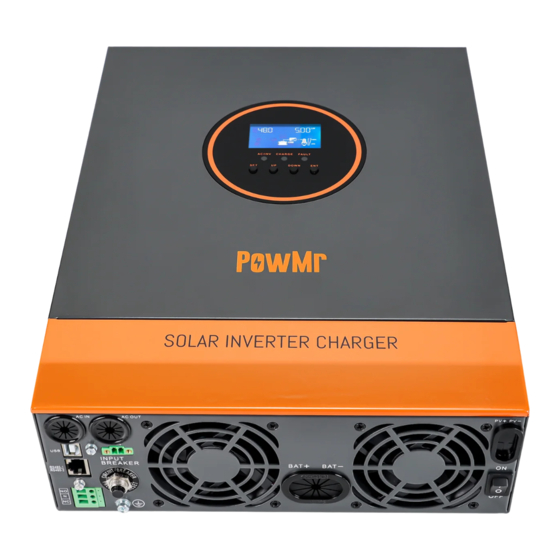
Page 8: Production Overview
Production Overview ⑨ Overload protector Dry contact port ② ⑩ ON/OFF rocker switch Cooling fan ③ ⑪ AC input port Battery port ④ ⑫ AC output port Cooling fan ⑤ ⑬ Grounding screw hold PV port ⑥ ⑭ RS485-2 communication port Touch the key lightly ⑦... -
Page 9: Dimension Drawing
Dimension Drawing... -
Page 10: Installation
Installation Installation Installation Notice Before installation, please carefully read the manual and get familiar with the installation step. ⚫ Take care while installing the battery. When installing the lead-acid liquid battery, it is required to wear goggles. Any body part contacting the battery acid must be washed with clear water in time. -
Page 11: Select The Mount Location
Select the Mount Location ⚫ Confirm the installation position and heat dissipation space, confirm the installation position of all- in-one inverter, such as wall surface; ⚫ To install the all-in-one inverter, guarantee there is sufficient air flowing through the cooling fins of all-in-one inverter. -
Page 12: Preparation
Preparation Before connecting all wirings, please take off bottom cover by removing two screws as shown below. -
Page 13: Connection
Model Wire Diameter Max. PV input current Circuit breaker Spec POW-LVM5K-48V-N /10AWG 2P—25A Note: The voltage in series shall not exceed maximum PV input open-circuit voltage. ➢ Please refer to the table below for recommended AC input wire diameter and switch: Max. -
Page 14: Ac Input/Output Wiring
and all-in-one inverter or between all-in-one inverter and battery, use thicker wire to reduce voltage drop and improve system performance. NOTICE ⚫ Above wire diameter and breaker are only for reference. Please select appropriate wire diameter and breaker based on practical condition. AC Input/Output Wiring 1. -
Page 15: Pv Input Wiring
3. Correctly connect AC output wire in accordance with cable sequence and terminal position shown in the figure below. Please connect the ground wire at first, and then live wire and null wire. The ground wire is connected to the ground screw hold through shaped terminal. : Ground L: Live N: Neutral... -
Page 16: Battery Wiring
Battery Wiring 1. Before wiring, disconnect external breaker at first, and then confirm whether the used cable is thick enough. Please refer to section “Wiring Specification and Breaker Type”. BAT wire shall be connected with the machine via O-shaped terminal. It is recommended to use the O-shaped terminal with 6mm inside diameter. -
Page 17: Final Assembly
Final Assembly 1. After wiring, inspect whether the wires are correctly and firmly connected, especially whether the positive and negative input poles of the battery are correct, whether the positive and negative input poles of PV are correct, whether AC input is inaccurately connected to AC output terminal. 2. -
Page 18: Operating Mode
Operation Mode Operating Mode Charge Mode 1. Photovoltaic priority: In photovoltaic priority charge mode, mains charge is started only when photovoltaics is out of work. Make full use of solar energy for power generation in the daytime and transfer to the mains supply for charge to maintain electric quantity of the battery. It is suitable for areas with relatively stable power grid and relatively expensive electricity price. -
Page 19: Output Mode
Output Mode 1. Photovoltaic priority mode: Photovoltaic and battery supply power to the load. With diversified charge mode and optional output mode, when photovoltaic priority mode is selected, the green solar energy can be used as far as possible so as to achieve energy conservation and emission reduction. -
Page 20: Operation Instruction
Operation Instruction Operation Instruction Operation and Display Panel ⚫ Touchable Keys Function Key Description Enter/exit setting menu Last option DOWN Next option Confirm/enter option under setting menu ⚫ LED Indicators Indicator light Color Description Constant on: mains supply output AC/INV Yellow Flashing: inverter output Flashing: battery in charge... -
Page 21: Introduction To Lcd Screen
Introduction to LCD screen Icon Icon Function Function Indicating that AC input end Indicating that inverter circuit is in has been connected to working. power grid Indicates that the AC input Indicating that the machine is in mode in APL mode (wide mains supply bypass work mode voltage range) Indicating that PV input end has... - Page 22 indicating ≥75% load percentage. Indicating that present battery type of the machine is Indicating that buzzer is not enabled lithium battery Indicating that current battery type of machine is lead-acid Indicating alarm of machine battery Indicating that the battery is in Indicating that the machine is in fault charge state.
-
Page 23: Real-Time Data View Method
charging the battery terminal Indicating power grid power supply to ② ⑥ The arrow is not displayed load Indicates the battery terminal Indicating power grid power supply to ③ ⑦ supplying power to the inverter charge circuit circuit Indicating PV power supply to charge Indicating power supply from ④... -
Page 24: Setting Parameter
Setting Parameter Key operation description: To enter setting menu and exit from setting menu, please press key “SET”. After entering the setting menu, parameter number [00] shall flash. At this time, press keys “UP” and “DOWN” to select the parameter item code to be set. Afterwards, press key “ENT” to enter parameter editing state. - Page 25 Description Selectable option Cannot exceed the value of [14] settings. When parameter【01】=SOL/SBU, battery voltage is higher than the set value, the Bypass to battery [05] 57.6V default output is switched to battery from mains or generator at 48V~60V setting range. For photovoltaics priority charge, the AC [06] CSO charge is started only when photovoltaics is...
- Page 26 Description Selectable option For vented lead-acid battery, charge [08] FLd voltage at constant voltage is 58.4V and float charge voltage is 55.2V For gel lead-acid battery, charge voltage at [08] GEL default constant voltage is 56.8V and float charge voltage is 55.2V. Lithium iron phosphate battery L14/L15/L16 corresponds to lithium iron phosphate battery 14 strings/15 strings/16 strings;...
- Page 27 Description Selectable option 0.4V step is valid in case of a self-defined battery and lithium battery. So as to over discharge delay time, when the battery voltage is lower than parameter 【12】, the inverter output is turned off Over discharge delay [13] 5S default after delaying the time set with the time...
- Page 28 Description Selectable option time 900mins setting range at 5mins step is valid in case of a vented lead-acid battery and sealed lead-acid battery. For equalizing charge delay, 5mins ~ Equalizing charge 900mins setting range at 5mins step is valid [19] 120 default delay in case of a vented lead-acid battery and sealed lead-acid battery.
- Page 29 Description Selectable option after overtemperature is disabled, if the output overtemperature machine is turned off upon overtemperature, no output is turned on. When automatic restart after overtemperature is enabled, if the output is [24] ENA default turned off upon overtemperature, the output can be turned on after the machine cools down.
- Page 30 Description Selectable option When the parameter [32] setting item =BMS, you can choose to match the battery manufacturer's BMS protocol to communicate Battery BMS with BMS for the lithium battery protection. communication PAC=PACE,RDA=Ritar, AOG=ALLGRAND BATTERY, protocol OLT=OLITER,HWD=SUNWODA, DAQ=DAKING, WOW=SRNE, PYL=PYLONTECH,UOL=WEILAN [34] DIS default Disable this function.
- Page 31 Description Selectable option Settings this setting (valid when BMS communication is normal) Switches to inverter output mode when Switch to inverter capacity is greater than or equal to this [62] 100% default output SOC Settings setting (valid when BMS communication is normal)
-
Page 32: Battery Type Parameters
Battery Type Parameters For Lead-acid Battery: Battery type Sealed lead Colloidal lead Vented lead User-defined acid battery acid battery acid battery (USE) Parameters (SLD) (GEL) (FLD) Overvoltage disconnection voltage 40~60V Equalizing charge voltage 58.4V 56.8V 59.2V (Adjustable) 40~60V Boost charge voltage 57.6V 56.8V 58.4V... - Page 33 For Lithium Battery: Battery Type Lithium Lithium Lithium Ternary Ternary iron iron iron User- lithium lithium phosphate phosphate phosphate defined battery battery battery battery battery (USE) (N13) (N14) Parameters (L16) (L15) (L14) Overvoltage disconnection voltage Equalizing 40~60V charge voltage (Adjustable) Boost charge 53.2V 57.6V...
-
Page 34: Other Function
Other Function Other Function Dry Node Function Working principle: this dry node can control the switch of diesel generator to charge the battery. ① Under normal conditions, in this terminal, NC-N point is closed and NO-N point is opened; ② when the battery voltage reaches the low-voltage disconnection voltage point, the coil of the relay is energized and NO-N point is closed and NC-N point opened. -
Page 35: Protection
Protection Protection Protection Function Protection Function Note Current limiting When the charge current of the configured PV array exceeds the protection rated current of PV, it will be charged at the rated current. At night, because the battery voltage is greater than that of the Anti-reverse charge PV module, the battery shall be protected against discharge protection at night... -
Page 36: Meaning Of Fault Code
Meaning of Fault Code Affecting Fault Code Fault Name output or Note 【01】 BatVoltLow Battery undervoltage alarm Average overcurrent software protection for 【02】 BatOverCurrSw battery discharge 【03】 BatOpen No connection alarm of battery 【04】 BatLowEod Stop discharge alarm for battery undervoltage 【05】... - Page 37 Input 【29】 BusVoltLow Bus undervoltage protection Inverter stops when battery capacity is low 【32】 BatCapacityLowStop (setting BMS to enable validity) 【34】 CanCommFault CAN communication fault in parallel operation Check whether the communication line is BMS communication connected correctly and whether [33] is set to 【58】...
-
Page 38: Troubleshooting
Troubleshooting Fault Solving Measures Check whether the battery air switch or PV air switch is closed; No display on screen whether the switch is in "on" state; press any key on the screen to exit from the screen sleep mode. Charge battery Measure whether the battery voltage exceeds 60V, and disconnect overvoltage protection... -
Page 39: System Maintenance
System Maintenance System Maintenance ➢ In order to maintain the optimum and permanent operation performance, it is suggested to check the following items semiannually. 1. Confirm that the air flow around the all-in-one inverter will not be blocked. In addition, remove any dirt or debris from the radiator. -
Page 40: Technical Parameter
Technical Parameter Technical Parameter Model POW-LVM5K-48V-N AC Mode Rated input voltage 110/120Vac Input voltage range (90Vac-140Vac) Frequency 50Hz/ 60Hz (auto-sensing) 47±0.3Hz ~ 55±0.3Hz (50Hz); Frequency range 57±0.3Hz ~ 65±0.3Hz (60Hz); Overload/short-circuit protection Breaker Efficiency >95% Conversion time 10ms (Typical value) - Page 41 Peak power 10000VA Loaded motor capacity Output short-circuit protection Breaker Specification of bypass breaker Rated battery input voltage 48V (minimum start voltage 44V) 40.0Vdc~60Vdc ± 0.6Vdc Battery voltage range (under voltage alarm/ turn off voltage/ overvoltage alarm/ overvoltage restoration… settable LCD screen) Load ≤50W Power saving mode AC Charge...
- Page 42 -10℃ ~ 55℃ Operation temperature range Storage temperature range -25℃ ~ 60℃ Humidity range 5% to 95% (three-proof paint protection) ≤60dB Noise Thermal dissipation Forced cooling with adjustable air speed Communication interface USB/RS485 (WiFi/GPRS)/dry node control Dimension (L*W*D) 426mm*322mm*126mm Weight (kg) 11.5...
Need help?
Do you have a question about the POW-LVM5K-48V-N and is the answer not in the manual?
Questions and answers