Table of Contents
Advertisement
This manual contains all safety, installation and operating instructions for the POW-HPM Series all-in-one
solar charge inverter. Please read all instructions and precautions in the manual carefully before installation
and use.
Non-safety voltage exists inside the all-in-one solar charge inverter. To avoid personal injury, users shall not
disassemble the all-in-one solar charge inverter themselves. Contact our professional maintenance personnel
if there is a need for repair.
Do not place the all-in-one solar charge inverter within the reach of children.
Do not install the all-in-one solar charge inverter in harsh environments such as moist, oily, flammable or
explosive, or heavily dusty areas.
The mains input and AC output are high voltage, so please do not touch the wiring terminals.
The housing of the all-in-one solar charge inverter is hot when it is working. Do not touch it.
Do not open the terminal protective cover when the all-in-one solar charge inverter is working.
It is recommended to attach proper fuse or circuit breaker to the outside of the all-in-one solar charge inverter.
Always disconnect the fuse or circuit breaker near the terminals of PV array, mains and battery before
installing and adjusting the wiring of the all-in-one solar charge inverter.
After installation, check that all wire connections are tight to avoid heat accumulation due to poor connection,
which is dangerous.
The all-in-one solar charge inverter is off-grid. It is necessary to confirm that it is the only input device for load,
and it is forbidden to use it in parallel with other input AC power to avoid damage.
Important Safety Instructions
Please save these instructions for future use!
Please keep this manual for future use.
1
Advertisement
Table of Contents

Related Manuals for PowMr POW-HPM Series


Summary of Contents for PowMr POW-HPM Series
- Page 1 Please save these instructions for future use! Please keep this manual for future use. This manual contains all safety, installation and operating instructions for the POW-HPM Series all-in-one solar charge inverter. Please read all instructions and precautions in the manual carefully before installation and use.
-
Page 2: Table Of Contents
Table of Contents 1. GENERAL INFORMATION ........................3 1.1 PRODUCT OVERVIEW AND FEATURES ..................3 1.2 BASIC SYSTEM INTRODUCTION ....................4 1.3 APPEARANCE ..........................5 1.4 DIMENSION DRAWING ......................... 6 2. INSTALLATION INSTRUCTIONS ......................7 2.1 INSTALLATION PRECAUTIONS ....................7 2.2 WIRING SPECIFICATIONS AND CIRCUIT BREAKER SELECTION ..........8 2.3 INSTALLATION AND WIRING ....................... -
Page 3: General Information
1.1 Product overview and features POW-HPM series is a new all-in-one hybrid solar charge inverter, which integrates solar energy storage & means charging energy storage and AC sine wave output. Thanks to DSP control and advanced control algorithm, it has high response speed, high reliability and high industrial standard. -
Page 4: Basic System Introduction
1.2 Basic system introduction The figure below shows the system application scenario of this product. A complete system consists of the following parts: 1. PV module: Convert light energy into DC power, and charge the battery through the all-in-one solar charge inverter, or directly invert into AC power to drive the load. -
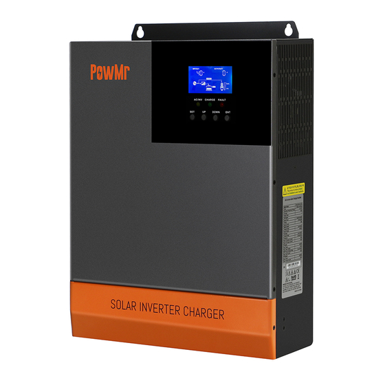
Page 5: Appearance
1.3 Appearance ① ⑩ Overload protector RS485-1 communication port ② ⑪ ON/OFF rocker switch Dry contact port ③ ⑫ AC input port Cooling fan ④ ⑬ AC output port Battery port ⑤ ⑭ Grounding screw hold Cooling fan ⑥ ⑮... -
Page 6: Dimension Drawing
1.4 Dimension drawing In ... -
Page 7: Installation Instructions
Installation instructions 2.1 Installation precautions Please read this manual carefully prior to installation to familiarize yourself with the installation steps. Be very careful when installing the battery. Wear safety goggles when installing a lead-acid liquid battery. Once coming into contact with the battery acid, rinse with clean water timely. Do not place metal objects near the battery to prevent short-circuit of the battery. -
Page 8: Wiring Specifications And Circuit Breaker Selection
2.2 Wiring specifications and circuit breaker selection Wiring and installation must comply with national and local electrical codes. Recommended PV array wiring specifications and circuit breaker selection: Since the output current of the PV array is affected by the type, connection method and illumination angle of the PV module, the minimum wire diameter of the PV array is calculated according to its short-circuit current;... -
Page 9: Installation And Wiring
2.3 Installation and wiring Installation steps:: Step 1: Determine the installation position and the space for heat dissipation. Determine the installation position of the all-in-one solar charge inverter, such as wall surface; when installing the all-in-one solar charge inverter, ensure that there is enough air flowing through the heat sink, and space of at least 200m m to the left and right air outlets of the inverter shall be left to ensure natural convection heat dissipation. - Page 10 Step 2: Remove the terminal cover Step3: Wiring AC input / output wiring method: ① Prior to AC input/output wiring, opening the external circuit breaker and confirm that the wire used is thick enough. Please refer to Section 2.2 “Wiring Specifications and Circuit Breaker Selection”; ②...
- Page 11 ③ Properly connect the AC output wire according to the wire sequence and terminal position shown in the figure below. Please connect the ground wire first, and then the live wire and the neutral wire. The ground wire is connected to the grounding screw hole on the cabinet through the O-type terminal. :Ground L:Live N:Neutral...
- Page 12 BAT wiring method: ① Prior to wiring, disconnect the external circuit breaker and confirm that the wire used is thick enough. Please refer to Section 2.2 “Wiring Specifications and Circuit Breaker Selection”. The BAT wire needs to be connected to the machine through the O-type terminal. The O-type terminal with an inner diameter of 5 mm is recommended.
- Page 13 Step 5: Install the terminals cover. Step 6: Turn on the all-in-one solar charge inverter First, close the circuit breaker at the battery terminal, and then turn the rocker switch on the left side of the machine to the "ON" state. The "AC/INV" indicator flashing indicates that the inverter is working normally.
-
Page 14: Parallel Machine Wire Connection
2.4 Parallel machine wire connection 2.4.1 Introduction Up to six units connected in parallel. When using the parallel operation function, the following connecting lines (package accessories) shall be firmly and reliably connected: DB15 Parallel communication line*1: Current sharing detection line*1: 2.4.2 Precautions for connecting the parallel connecting lines ... -
Page 15: Schematic Diagram Of Parallel Connection In Single Phase
Wiring of parallel communication line: Parallel connection in single or split phase: Our company's parallel communication line is a DB15 standard computer cable with shielding function. Ensure the "one-in-one-out" rule when connecting each inverter, that is, connect the male connector (out) of this inverter with the female connector (in) of the inverter to be paralleled. - Page 16 In case of parallel operation with multiple inverters, the schematic diagram of parallel connection is as follows: a) Two all-in-one solar charger inverters of the system connected in parallel: b) Three all-in-one solar charger inverters of the system connected in parallel:...
- Page 17 c) Four all-in-one solar charger inverters of the system connected in parallel: d) Five all-in-one solar charger inverters of the system connected in parallel: e) Six all-in-one solar charger inverters of the system connected in parallel:...
-
Page 18: Schematic Diagram Of Parallel Connection In Spilit Phase
2.4.4 Schematic diagram of parallel connection in split phase The parallel communication line and current sharing detection line of the all-in-one solar charger inverter need to be locked with screws after connecting. The schematic diagram is as follows: In case of parallel operation with multiple inverters, the schematic diagram of parallel connection is as follows: Parallel Operation in three phase : a)... - Page 19 c) Five all-in-one solar charger inverters of the system connected in three phase: 3+1+1 system: 2+2+1 system:...
- Page 20 d) Six all-in-one solar charger inverters of the system connected in three phase: 2+2+2 system: 3+2+1 system: 4+1+1 system:...
- Page 21 Note: Before starting up and running, please check whether the connection was correct to avoid any abnormalities in the system. All wiring must be fixed and reliable to avoid wire drop during use. When the AC output is wired to the load, it shall be properly wired according to the requirements of the electrical load equipment to avoid damage to the load equipment.
-
Page 22: Operating Modes
Operating modes 3.1 Charging mode 1) PV priority: PV module will charge the battery preferentially, and the battery is charged by the Mains only when the PV system fails. During the day, solar energy is fully used to charge, while at night, it converts to the Mains. -
Page 23: Output Mode
3.2 Output mode 1) PV priority mode: Switch to mains supply when the PV charging fails. This mode maximizes the use of solar energy while maintaining battery power, suitable for use in the areas with relatively stable grid. Power supply priority: Solar—》Utility—》Battery. -
Page 24: Lcd Screen Operating Instructions
LCD screen instructions 4.1 Operation and display panel The operation and display panel is as shown below, including 1 LCD screen, 3 indicators and 4 operation buttons. Operation buttons introduction Function Description buttons Enter/Exit Settings menu Previous choice DOWN Next choice Confirm/Enter Options under the settings menu, Indicators introduction... - Page 25 LCD screen introduction Icons Functions Icons Functions Indicates that the AC input Indicates that the inverter terminal has been connected circuit is working to the grid Indicates that the AC input Indicates that the machine mode in APL mode (wide is in the Mains Bypass voltage range) mode...
- Page 26 The parameters displayed in the middle of the screen: 1. In the non-setup mode, Indicates that the AC output the alarm or fault code is terminal has an AC voltage displayed. 2. In the setup output mode, the currently set parameter item code is displayed.
- Page 27 Real-time data viewing method On the LCD main screen, press the “UP” and “DOWN” buttons to scroll through the real-time data of the machine. Parameters Parameters on the left side of in the Parameters on the right side of the Page the screen middle of...
-
Page 28: Setup Parameters Description
4.2 Setup parameters description Buttons operation instructions: Press the “SET” button to enter the setup menu and exit the setup menu. After entering the setup menu, the parameter number [00] will flash. At this point, press the “UP” and “DOWN” buttons to select the code of parameter item to be set. - Page 29 Paramete Parameter name Settings Description r no. S series model:setting range 0~80A; User-defined; all battery parameters can be [08] USE set. Sealed lead-acid battery; constant-voltage [08] SLd charge voltage: 57.6V, floating charge voltage: 55.2V. Vented lead-acid battery; constant-voltage [08] FLd charge voltage: 58.4V, floating charge voltage: 55.2V.
- Page 30 Paramete Parameter name Settings Description r no. Equalizing charge voltage; setting range: Battery [17] 58.4V 48V~58.4V, with a step of 0.4V; valid for equalization default vented lead-acid battery and sealed lead-acid voltage battery Equalizing charge time; setting range: Battery equalized [18] 120 5min~900min, with a step of 5 minutes;...
- Page 31 Paramete Parameter name Settings Description r no. standby mode [31] PAL In parallel operation with single phase. Please only) default refer to 2.4 Wiring Diagram. [31] In split phase operation with three phase. At 3P1/3P2/3P least one inverter is required for each phase. Please refer to 2.4 Wiring Diagram.
-
Page 32: Battery Type Parameters
4.3 Battery type parameters For Lead-acid Battery : Colloidal Battery type Sealed lead Vented lead lead acid User-defined acid battery acid battery battery (User) Parameters (SLD) (FLD) (GEL) Over voltage 36~60V disconnection voltage (Adjustable) Battery fully charged recovery point(setup (Adjustable) (Adjustable) (Adjustable) - Page 33 For Lithium Battery : Battery type Ternary Ternary LFP battery LFP battery LFP battery lithium lithium (L16) (L15) (L14) Parameters battery (N13) battery (N14) Over voltage disconnection voltage Battery fully charged 50.4V 54.8V 53.6V 50.4V 47.6V recovery point(setup (Adjustable) (Adjustable) (Adjustable) (Adjustable)
-
Page 34: Other Functions
Other functions instructions 5.1 Dry contact Working principle: This dry contact can control the ON/OFF of the diesel generator to charge the battery. ①Normally, the terminals are that the NC-N point is closed and the NO-N point is open; ②... -
Page 35: Protection
Protection 6.1 Protections provided Protections Description PV current/power limiting When charging current or power of the PV array configured protection exceeds the PV rated, it will charge at the rated. At night, the battery is prevented from discharging through the PV PV night reverse-current module because the battery voltage is greater than the voltage of protection... -
Page 36: Fault Code
6.2 Fault code Whether it Fault code Fault name affects the Description output or not BatVoltLow Battery under voltage alarm 【01】 Battery discharge average current over current 【02】 BatOverCurrSw software protection 【03】 BatOpen Battery not-connected alarm BatLowEod Battery under voltage stop discharge alarm 【04】... - Page 37 BatCapacityLowSto Inverter stops when battery capacity is low 【32】 (setting BMS to enable validity) 【34】 CanCommFault CAN communication fault in parallel operation 【35】 ParaAddrErr Parallel ID setting error 【36】 ParaShareCurrErr Parallel current sharing fault 【37】 Large battery voltage difference in parallel 【38】...
-
Page 38: Handling Measures For Part Of Faults
6.3 Handling measures for part of faults Fault Faults Remedy code Check if the battery the PV air switch has been closed; if the switch is in the "ON" state; press Display No display on the screen any button on the screen to exit the screen sleep mode. -
Page 39: Troubleshooting
Troubleshooting In order to maintain the best long-term performance, it is recommended to conduct following checks twice a year. Make sure that the airflow around the unit is not blocked and remove any dirt or debris from the heat sink. 2. -
Page 40: Technical Parameters
Technical parameters Models POW-HPM5.6KW Parallel mode Permitted parallel number AC mode Rated input voltage 220/230Vac (170Vac~280Vac) ±2% Input voltage range (90Vac-280Vac) ±2% Frequency 50Hz/ 60Hz (Auto detection) 47±0.3Hz ~ 55±0.3Hz (50Hz); Frequency Range 57±0.3Hz ~ 65±0.3Hz (60Hz); Overload/short circuit protection Circuit breaker Efficiency >95%... - Page 41 Overcharge protection Alarm and turn off charging after 1 minute PV charging Maximum PV open circuit 500Vdc voltage PV operating voltage range 120-500Vdc MPPT voltage range 120-450Vdc Battery voltage range 40-60Vdc Maximum PV input power 6000W Maximum PV input current PV charging current range (can 0-80A be set)
Need help?
Do you have a question about the POW-HPM Series and is the answer not in the manual?
Questions and answers