Table of Contents
Advertisement
Quick Links
Advertisement
Table of Contents

Related Manuals for PowMr POW-SunSmart 8KP


Summary of Contents for PowMr POW-SunSmart 8KP
- Page 1 Parallel Version...
-
Page 2: Important Safety Instructions
Important Safety Instructions Please save these instructions for future use! Read all of the instructions and cautions in the manual before beginning the installation ! ⚫ Installation and wiring must comply with the Local and National Electric Codes (NEC) and must be done by a certified technician. -
Page 3: Table Of Contents
Table of Contents Important Safety Instructions..........................1 1 Safety ..................................2 1.1 How to Use This Manual ........................2 1.2 Symbols in This Manual ......................... 2 1.3 Safety Instructions ..........................3 2 Production Instructions ............................ 4 2.1 Instructions ............................... 4 2.2 Features .............................. - Page 4 5.6 Battery Parameters ..........................38 6 Communication ..............................40 6.1 Overview ..............................40 6.2 USB-B Port ............................. 40 6.3 WIFI Port ..............................41 6.4 RS485/CAN Port ............................ 41 6.5 Dry Contact Port ........................... 42 7 Fault Codes and Response Measures ......................44 7.1 Fault Codes .............................
-
Page 5: Safety
1 Safety 1.1 How to Use This Manual This manual contains important information,guidelines,operation and maintenance for the following products: POW-SunSmart 10KP and POW-SunSmart 8KP The manual must be followed during installation and maintenance. 1.2 Symbols in This Manual Symbol Description... -
Page 6: Safety Instructions
1.3 Safety Instructions DANGER ⚫ This chapter contains important safety instructions. Read and keep this manual for future reference. ⚫ Be sure to comply the local requirements and regulation to install this inverter. ⚫ Beware of high voltage. Please turn off the switch of each power sources before and during the installation to avoid electric shock. -
Page 7: Production Instructions
2 Production Instructions 2.1 Instructions POW-SunSmart series is a new type of solar energy storage inverter control inverter integrating solar energy storage & utility charging and energy storage, AC sine wave output. It adopts DSP control and features high response speed, reliability, and industrial standard through an advanced control algorithm. - Page 8 cutting in/out of mains charging and switch the time period between battery discharging and mains bypass power supply mode. ⚫ Energy saving mode function to reduce no-load energy losses. ⚫ With two output modes of utility bypass and inverter output, with uninterrupted power supply function.
-
Page 9: System Connection Diagram
2.3 System Connection Diagram The diagram below shows the system application scenario of this product. A complete system consists of the following components: 1. PV modules: converts light energy into DC energy, which can be used to charge the battery via an inverter or directly inverted into AC power to supply the load. -
Page 10: Production Overview
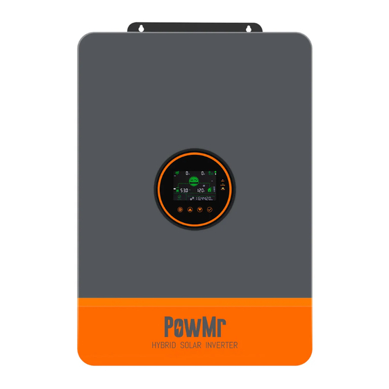
2.4 Production Overview LCD Screen LED Indicators Touchable key ON/OFF Rocker Switch PV INPUT (1/1) BAT INPUT (+) BAT INPUT (-) Dry contact CAN/RS485 port WIFI Port USB-B port Grounding Screw AC OUT (L+L+N) AC IN (L1+L2+N) AC INPUT breaker Parallel Communication Port... -
Page 11: Installation
3 Installation 3.1 Select the Mount location POW-SunSmart series are designed for INDOOR USE ONLY (IP20) . Please consider the followings before selecting the location. ⚫ Choose the solid wall to install the inverter. ⚫ Mount the inverter at eye level. ⚫... -
Page 12: Mount The Inverter
3.2 Mount the Inverter Make 4 mounting holes in the wall with an electric drill according to the specified dimensions, insert 2 expansion screws above and fix the inverter with 2 M5 screws below. 3.3 Remove the Terminal Cover and Insect Screen Using a screwdriver, remove the terminal protection cover and insect screen. -
Page 13: Connection
4 Connection 4.1 Connection Overview ⚫ Split-phase mode(default) AC Output 120V 240V 120V Items Description Applicable Model POW-SunSmart series U model Output Voltage Range (L-N) 100~120Vac, 120Vac default Output Voltage Range (L-L) 200~240Vac,240Vac default ⚫ Single-phase mode AC Output L1,L2 120V 120V L1&L2 are in the same phase and... -
Page 16: Cable & Circuit Breaker Requirement
4.2 Cable & Circuit Breaker Requirement ⚫ PV INPUT Model Cable Diameter Max.PV Input Current Circuit Breaker Spec POW-SunSmart 8KP 5mm² / 10 AWG 2P-25A POW-SunSmart 10KP 5mm² / 10 AWG 2P-25A ⚫ AC INPUT Circuit Output Max. Input Cable... - Page 17 ⚫ AC OUTPUT Circuit Output Max.Output Model Diagram Cable diameter Breaker Mode Current Spec Split- 13mm² /6AWG 3P-63A phase (L1/L2/N) (L1\L2\N) POW- SunSmart 13mm² Single- 42A (L1/L2) /6AWG(L1/L2) 2P-125A phase 84A(N) 26mm² /3AWG(N) Split- 13mm² /6AWG 3P-63A phase (L1/L2/N) (L1\L2\N) POW- SunSmart 13mm²...
-
Page 18: Ac Input & Output Connection
4.3 AC Input & Output Connection Connect the live, neutral and ground wires according to the cables’ position and order shown in the diagram below. DANGER ⚫ Before connecting AC inputs and outputs, the circuit breaker must be opened to avoid the risk of electric shock and must not be operated with electricity. -
Page 19: Pv Connection
DANGER ⚫ Before connecting battery, the circuit breaker must be opened to avoid the risk of electric shock and must not be operated with electricity. ⚫ Make sure that the positive and negative terminals of the battery are connected correctly and not reversed, otherwise the inverter may be damaged. -
Page 20: Dry Contact Connection
4.6 Dry Contact Connection Use a small screwdriver to push back the direction indicated by the arrow, then insert the communication cable into the dry junction port. (Communication cable diameter 0.2~1.5mm²) 4.7 Grounding Connection Please make sure the grounding terminal connect to the Grounding Busbar. NOTICE ⚫... -
Page 21: Operation
5 Operation 5.1 Operation and Display Panel The operation and display panel below includes 1 LCD screen, 3 indicators, 4 touchable keys. ⚫ Touchable Keys Touchable Keys Description Enter/exit the setting menu Go to the next selection Go to the previous selection Confirm/Enter the selection in setting menu ⚫... - Page 22 ⚫ Display panel Icon Description Icon Description Indicates the PV panel Indicates the utility grid Indicates the battery Indicates the generator Indicates the inverter is Indicates the home load working Indicates the inverter is communicating with data Indicates the buzzer muted collector Indicates the direction of energy flow Indicates the inverter is...
- Page 23 Indicates load power Indicates battery SOC 40%~59% 40%~59% Indicates load power Indicates battery SOC 20%~39% 20%~39% Indicates load power Indicates battery SOC 5%~19% 5%~19% END OF UNDER Indicates battery under- Indicates battery discharge VOLT DISCHG voltage OVER BMS FAULT Indicates over-load Indicates BMS fault LOAD Indicates system...
- Page 24 ⚫ View real-time data In the main screen, press the UP / DOWN keys to view the real-time data of the inverter during operation. NOTICE UP/DOWN Main Screen View Real-Time Data Real-Time Page PV side BAT side AC IN side LOAD side General Single phase...
-
Page 25: Setting
5.2 Setting NOTICE UP/DOWN Main Screen Enter Setup Menu View Parameter ENTER Edit Parameter UP/DOWN Set Parameter ENTER Confirm Parameter Parameter ID Parameter option Parameter Options Description Meaning Exit Exit the setup menu. Mains first. Grid power supply is to be applied first. - Page 26 switch to the mains mode for loading. When the battery voltage is higher than the set value in the item 5, it will switch back to the PV mode from the mains mode. The PV mode is to be applied first and when the PV power is unavailable or the battery voltage is lower than the set value in the item 4, it will switch to...
- Page 27 PV charge first, and enable the mains mode only when PV power. Do not enable the mains charge mode when in only PV charge mode. POW-SunSmart 8KP current setting range:0~180A Battery charging current POW-SunSmart 10KP current setting range:0~200A.
- Page 28 Setting range:48V~58.4V, increment of Battery boost each click is 0.4V, parameter can be set 57.6 charging voltage only when battery type is USER and L14/15/16, N13/14. The continuous charging time when the voltage reaches the set voltage Boost charging during constant voltage charging, with duration a setting range of 5 min−900 min and a step of 5 min.
- Page 29 shuts down. Setting range: 40 V−52 V, with a step of 0.4 V, available for user- defined and Li-ion batteries. Disable equalization charging. Battery Enable equalization charging, equalization ENA default parameter can be set only when charging battery type is FLd\SLd\USER Setting range: 48V~58V, increment of Battery each click is 0.4V, parameter can be set...
- Page 30 output will switch off after a 5min delay . When the load is more than 50W, the inverter automatic restart. Disable overload auto restart and when overload occurs, it will turn off the output and the inverter will no longer resume startup. Enable overload auto restart, and If Over-load restart overload occurs, the output will be...
- Page 31 Enable auto switch to mains for ENA default loading in case of inverter overload. POW-SunSmart 8KP, setting range: Max. charging 0~100A. current POW-SunSmart 10KP, setting range: 0~120A. RS485 RS485 communication address setting communication ID: 1 range: 1~254.
- Page 32 P3. 1) Assuming that the output voltage of the setting item [38] is set to 120 VAC: then the voltage phase difference of P1-P2, P1-P3, and P2-P3 is 120°, the voltage between the live wire L1 of phase-P1 and the live wire L2 of phase-P2 is 120*1.732=208 VAC, and similarly the voltage of L1-L3 and L2-L3 is 208 VAC;...
- Page 33 threshold than the threshold to restore the AC output of the battery inverter. Setting range: 44 V−54.4 V. After the battery is fully charged, the Recharge voltage inverter stops charging, and recovers threshold for fully charging when the battery voltage is charged battery lower than the threshold.
- Page 34 DIS default Disable this function. After the timed mains charge/loading function is enabled, the power supply mode will turn into SBU, where mains is available for power supply in the set period or after battery over-discharge. If the timed discharge function is Time slot charging enabled at the same time, the power function...
- Page 35 mode will be changed into UTI, where the system only switches to the power supply of battery inverter during the set discharge period or mains failure. YY/MM/DD. Current date 00:00:00 Setting range: 00:01:01-99:12:31. Current time 00:00:00 Setting range: 00:00:00-23:59:59. The charge stops when the charge Charge stop current current is less than the set value.
- Page 36 Auto N-PE DIS default Disable auto N-PE connection switch. connection switch function Enable auto N-PE connection switch. Power sales setting 0 default Setting range: 0−rated power. 0 represents the single-phase mode Assuming that the AC output voltage of item 38 is 120 V, the phase difference of L1-L2 is 0°, and L1/L2 can be connected in parallel, the phase voltage of L1-N/L2-N is 120 V.
-
Page 37: Ac Output Mode
5.3 AC Output Mode The AC output mode corresponds to parameter setting item 01 and 34, which allows the user to set the AC output power source manually. (default) ⚫ Utility Priority Output 01 UTI Utility at first priority, utility and solar provide power to load at the same time when solar is available, battery will provide power to load only when utility power is not available. -
Page 38: Battery Charging Mode
⚫ Inverter Priority Output 01 SbU Solar provides power to the loads as first priority. If solar is not sufficient or not available, the battery will be used as a supplement to provide power to the loads. When the battery voltage reaches the value of parameter 04(Voltage point of battery switch to utility) will switch to utility to provide power to the load, This model makes maximum use of DC energy and is used in areas where the grid is stable. - Page 39 ⚫ Solar Priority Charging CSO Solar priority charging, with utility charging only activated when the solar fails. By making full use of solar power during the day and switching to utility charging at night, battery power can be maintained and is suitable for applications in areas where the grid is relatively stable and electricity prices are more expensive.
-
Page 40: Time-Slot Charging/Discharging Function
5.5 Time-slot Charging/Discharging Function The POW-SunSmart series is equipped with a time-slot charging and discharging function, which allows users to set different charging and discharging periods according to the local peak and valley tariffs, so that the utility power and PV energy can be used rationally. When mains electricity is expensive, the battery inverter is used to carry the load;... -
Page 41: Battery Parameters
5.6 Battery Parameters ⚫ Lead-acid battery Battery type User- Sealed Flooded defined Parameter USER Over-voltage cut-off voltage 40~60V Equalization charging voltage 56.8V settable 40~60V Bulk charging voltage 57.6V 56.8V 57.6V settable 40~60V Float charging voltage 55.2V 55.2V 55.2V settable 40~60V Under-voltage alarm voltage settable Under-voltage cut-off... - Page 42 ⚫ Li-ion battery Battery type User- Ternary Li-ion defined Parameter USER Over-voltage cut-off voltage Equalization charging 40~60V voltage settable 40~60V Bulk charging voltage 53.2V 57.6V 56.8V 53.2V 49.2V settable 40~60V Float charging voltage 53.2V 57.6V 56.8V 53.2V 49.2V settable Under-voltage alarm 40~60V 43.6V 46.8V...
-
Page 43: Communication
Users can use the upper computer software through the port to read and modify device parameters. If needing the installation package for the upper computer software, you can download it from the official website of PowMr, or contact us to get it. -
Page 44: Wifi Port
6.3 WIFI Port The WIFI port is used to connect to the Wi-Fi/GPRS data acquisition module, and then users can view the operation status and parameters of the inverter via the mobile APP. RJ45 Definition Pin 1 Pin 2 Pin 3 Pin 4 Pin 5 Pin 6... -
Page 45: Dry Contact Port
6.5 Dry Contact Port The dry contact port has 4 functions: 1. Remote ON/OFF 3. Battery temperature sampling 2. ON/OFF signal output 4. Remote generator start/stop Switching signal output Temperature sampling (reserved) Remote on/off Generator remote on/off Function Description When pin 1 is connected with pin 2, the inverter will switched off Remote switch on/off the AC output. -
Page 46: Fault Codes And Response Measures
7 Fault Codes and Response Measures 7.1 Fault Codes Alarm Fault code Fault Does it Affect Meaning Instructions Code the outputs BatVoltLow Battery under-voltage alarm Overcurrent software protection for BatOverCurrSw average battery discharge current BatOpen Battery disconnected alarm Battery under-voltage stop BatLowEod discharging alarm Battery over-current hardware... - Page 47 protection AuxDSpReqOffPWM Slave chip request switch off failure InvShort Inverter short-circuit protection Bussoftfailed Busbar soft start failure MPPT heat sink over-temperature OverTemperMppt protection Inverter heat sink over-temperature OverTemperInv protection FanFail Fan failure EEPROM Memory failure ModelNumErr Wrong model Busdiff Busbar voltage imbalance BusShort Busbar short circuit Rlyshort...
- Page 48 InvDcVoltErr Inverter DC voltage error Inconsistent system firmware version in SysFwVersionDiff parallel mode ParaLineContErr Parallel connection fault Failure to set the serial number before Serialnumbererror leaving factory Errorsettingofsplit- Setting error of setting items in parallel mode phasemode Lowinsulation Abnormally low earth impedance of PV1+ PV2+, and PV- resistancefault Leakagecurrent...
-
Page 49: Trouble Shooting
7.2 Trouble Shooting Fault Code Meaning Causality Remedy Check if the battery air-switch or There is no power PV air-switch has been closed; No screen input, or the device check if the switch is in "ON"; display switch at its bottom is press any button on the screen not turned on. - Page 50 Inverter output power Inverter over- or output current load(software overload for a certain detection) period of time. Heat sink of PV input over- Heat sink of PV input temperature temperature exceeds Resume normal charge and (software 90℃ for 3s. discharge when the temperature detection) of the heat sink has cooled to Heat sink of...
-
Page 51: Protection Function And Product Maintenance
8 Protection Function and Product Maintenance 8.1 Protection Function Protection Feature Instruction When the charge current or power of the configured PV PV current-limiting array exceeds the rated current and power of the inverter, it protection will charge at the rated current and power. If the PV voltage exceeds the maximum value allowed by the PV input over- hardware, the machine will report a fault and stop the PV... - Page 52 When a short-circuit fault occurs at the load output AC output short- terminal, it will immediately turn off the output of AC circuit protection voltage. Only after manually powering on the device, normal output restores. When the internal temperature of the inverter is too high, Heat sink over- the inverter will stop charging and discharging;...
-
Page 53: Maintenance
8.2 Maintenance To maintain optimum and long-lasting working performance, we recommend that the following items are checked twice a year. 1. Ensure that the airflow around the inverter is not blocked and remove any dirt or debris from the radiator. 2. -
Page 54: Parameter Table
9 Parameter Table CAN BE MODEL POW-SunSmart 8KP POW-SunSmart 10KP INVERTER OUTPUT Rated Output Power 8,000W 10,000W Max. Peak Power 16,000W 20,000W Rated Output Voltage 120/240Vac (split phase/single phase) Rated AC Frequency 50/60Hz Waveform Pure Sine Wave Switch Time 10ms (typical) - Page 55 Max. Input current 22/22A Max. Voltage of Open Circuit 500Vdc MPPT Voltage Range 125-425Vdc MAINS / GENERATOR INPUT Input Voltage Range 90-140Vac Frequency Range 50/60Hz Bypass Overload Current EFFICIENCY MPPT Tracking Efficiency 99.9% Max. Battery Inverter Efficiency GENERAL Dimensions 620*445*130mm(2*1.5*0.4ft) Weight 27kg(59.5lb)...
-
Page 56: Appendix: Parallel Connection
10 Appendix: Parallel Connection 10.1 Parallel Operation 1. The parallel operation supports up to six solar storage inverters. 2. When using the parallel function, it is necessary to connect the parallel communication cable in a correct and reliable manner. See the figure blow for the communication cable (packaging accessory): Parallel communication cable*1 10.1.1 Cautions for Parallel Connection... - Page 57 4. AC IN wiring: In single-phase parallel connection, all solar storage inverters must be connected in the manner of L-to-L, N-to-N, and PE-to-PE, and before power on and start-up, it is necessary to check and ensure correct connection, wiring length, and cable size, so as to avoid the abnormal operation of parallel system output caused by wrong connection.
- Page 58 10.1.2 Wiring diagram for single-phase parallel connection (phase difference between L1 and L2: 0°) ⚫ The communication cable of parallel solar storage inverter is to be locked with screws after connecting. See the diagram below: ⚫ See the diagram below for parallel connection. Set the item [31] to "PAL"...
- Page 59 2. Three parallel-connected solar storage inverters: 3. Four parallel-connected solar storage inverters:...
- Page 60 4. Five parallel-connected solar storage inverters: 5. Six parallel-connected solar storage inverters:...
- Page 61 10.1.3 Wiring diagram for two-phase parallel connection (phase difference between L1 and L2: 0°) 1) P1: Set the item [31] to "2P0;" P2: Set the item [31] to "2P1," all of the P1/P2 inverter item [68] can not be set, it is default “0°”and the phase difference between P1 and P2 is 120°. When setting the item [38] to "120 V,"...
- Page 62 b. Split-phase system (three inverters) 2+1 system c. Split-phase system (four inverters) 3+1 system:...
- Page 63 2+2 system:...
- Page 64 d. Split-phase system (five inverters) 4+1 system: 3+2 system:...
- Page 65 e. Split-phase system (six inverters) 5+1 system: 4+2 system:...
- Page 66 3+3 system:...
- Page 67 10.1.4 Wiring diagram for split-phase parallel connection (phase difference between L1 and L2: 180°) Set the item [31] to PAL, and set the item [68] to 180°. When setting the item [38] to "120 V," the L1-L2 voltage is 240 V, and the L1-N voltage is 120 V, L2-N voltage is 120V a.
- Page 68 c. Four parallel-connected solar storage inverters: d. Five parallel-connected solar storage inverters:...
- Page 69 e. Six parallel-connected solar storage inverters:...
- Page 70 10.1.5 Wiring diagram for three-phase parallel connection P1: Set the item [31] to "3P1;" P2: Set the item [31] to "3P2;" P3: Set the same to "3P3", all of P1/P2/P3 inverters item [68] can not be set, it is default “0°”. At this point, the P1-P2, P1-P3, and P2-P3 phase difference is 120°.
- Page 71 b. Three-phase system (four inverters) 2+1+1 system: c. Three-phase system (five inverters) 3+1+1 system:...
- Page 72 2+2+1 system: d. Three-phase system (six inverters) 2+2+2 system:...
- Page 73 3+2+1 system: 4+1+1 system:...
- Page 74 Note: 1. Before powering on and lighting up the screen, check for correct wiring according to the above wiring diagrams to avoid system problems. 2. Check all connections for firm fixing to avoid detachment and abnormal system operation. 3. When connecting the AC output to the load, complete wiring according to the requirements of the electrical load to avoid damage to the load.
- Page 75 In split-phase parallel operation: Set the item [31] to PAL, and set the item [68] to 180°. When setting the item [38] to "120 V," the L1-L2 voltage is 240 V, and the L1-N voltage is 120 V. In three-phase parallel operation: P1: Set the item [31] to "3P1;"...
Need help?
Do you have a question about the POW-SunSmart 8KP and is the answer not in the manual?
Questions and answers