Oki B8300n Service Manual
Hide thumbs
Also See for B8300n:
- Limited warranty (17 pages) ,
- Specifications (2 pages) ,
- User manual (95 pages)
Table of Contents
Advertisement
Quick Links
[ 1 ] GENERAL . . . . . . . . . . . . . . . . . . . . . . . . . . . . . . . . . . . . . . . . 1 - 1
[ 2 ] CONFIGURATION . . . . . . . . . . . . . . . . . . . . . . . . . . . . . . . . . . 2 - 1
[ 3 ] SPECIFICATIONS . . . . . . . . . . . . . . . . . . . . . . . . . . . . . . . . . . 3 - 1
[ 4 ] CONSUMABLE PARTS . . . . . . . . . . . . . . . . . . . . . . . . . . . . . . 4 - 1
[ 5 ] EXTERNAL VIEWS AND INTERNAL STRUCTURES . . . . . . . 5 - 1
[ 6 ] UNPACKING AND INSTALLATION . . . . . . . . . . . . . . . . . . . . . 6 - 1
[ 7 ] DISASSEMBLY AND ASSEMBLY, MAINTENANCE. . . . . . . . . 7 - 1
[ 8 ] MACHINE OPERATION . . . . . . . . . . . . . . . . . . . . . . . . . . . . . . 8 - 1
[ 9 ] ADJUSTMENTS . . . . . . . . . . . . . . . . . . . . . . . . . . . . . . . . . . . . 9 - 1
[10] DIAG . . . . . . . . . . . . . . . . . . . . . . . . . . . . . . . . . . . . . . . . . . . . 10 - 1
[11] TROUBLE CODES . . . . . . . . . . . . . . . . . . . . . . . . . . . . . . . . . 11 - 1
[12] PART NUMBERS . . . . . . . . . . . . . . . . . . . . . . . . . . . . . . . . . . 12 - 1
[13] OTHERS . . . . . . . . . . . . . . . . . . . . . . . . . . . . . . . . . . . . . . . . 13 - 1
S
ERVICE
LASER PRINTER
MODEL B8300n
CONTENTS
M
ANUAL
Advertisement
Table of Contents

Related Manuals for Oki B8300n


Summary of Contents for Oki B8300n
- Page 1 ANUAL LASER PRINTER MODEL B8300n CONTENTS [ 1 ] GENERAL ........1 - 1 [ 2 ] CONFIGURATION .
- Page 2 CAUTION Cautions on laser +10 nm At the production line, the output power of the scanner unit 785 nm Wave length −15 nm is adjusted to 0.4 MILLIWATT PLUS 8 % and is maintained constant by the operation of the Automatic Power Control (APC). North America: Pulse times 35 cpm model: (4.1 µs ±...
- Page 3 CAUTION FOR BATTERY DISPOSAL (For USA,CANADA) Contains lithium-ion battery. Must be disposed of properly. Remove the battery from the product and contact federal or state environmental agencies for information on recycling and disposal options.
- Page 4 Other options ....... 5 LASER PRINTER MODEL B8300n _______________________ 1 [7] DISASSEMBLY AND ASSEMBLY, MAINTE- NANCE ..............
- Page 5 [10] DIAG ............1 Diag mode ......1 Entering Diag mode ......1 Selecting Diag menus .
-
Page 6: Note For Servicing
The following items are normally prohibited from printing by national law. Other items may be prohibited by local law. • Money • Stamps • Bonds • Stocks • Bank drafts • Checks • Passports B8300n GENERAL 1-1 Rev. 1 12/10/02... -
Page 7: System Configurations
(B83LT), or Three paper drawer stand (B83TT) Power Supply Unit (B83PS) is required for Stand/MPD&2000 Sheet Paper Drawer (B83LT), Three paper drawer stand (B83TT), Finisher (B83F), Saddle stitch finisher (B83SS), or Mail- bin stacker (B83MB). B8300n CONFIGURATION 2-1 Rev. 1 12/10/02... - Page 8 Must be installed together Any of the units must be installed together Must be installed for installation of the stand/3x500 sheet paper drawer or the stand/ MPD & 2000 sheet drawer Cannot be installed together B8300n CONFIGURATION 2-2 Rev. 1 12/10/02...
-
Page 9: Basic Specification
The actual Weight Approx. 85.98 lbs (39 kg) printable area depends on the printer driver used. Approx. 110.23 lbs (50 kg) (with multi- purpose tray and upper exit tray extension) B8300n SPECIFICATIONS 3-1 Rev. 1 12/10/02... - Page 10 8½ x 13, A3, B4) do not contain the “R” in their size indication. Source selection Different first page Transparency inserts 3. Paper output PCL5e/ Function PCL6 (Windows) (Macintosh) Output tray selection Mail bin Staple Offset Punch B8300n SPECIFICATIONS 3-2 Rev. 1 12/10/02...
-
Page 11: Specification
2/4/6/9/16 is supported in the Windows 2000 environment. Only one size is supported in the Windows 2000 environment. Only 35 fonts are supported in the Windows NT 4.0 environment. This function is limited for PPD. PCL6 only B8300n SPECIFICATIONS 3-3 Rev. 1 12/10/02... -
Page 12: Consumable Parts
Indicates the production day. Numeral figure or X, Y, Z Indicates the production month. X stands for October, Y November, and Z December. Serial No. Label Serial No. Label on Bag Heat seal Aluminum bag B8300n CONSUMABLE PARTS 4-1 Rev. 1 12/10/02... -
Page 13: Environmental Conditions
Indicates the production month. (Without dew condensation) X stands for October, Y November, and Z December. B. Storage conditions Serial Number Label Serial No. label on bag Temperature (Without dew condensation) Heat seal Aluminum bag B8300n CONSUMABLE PARTS 4-2 Rev. 1 12/10/02... -
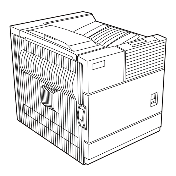
Page 14: External Views And Internal Structures
1, 2, 3, 5, 10, 11, and 12 are peripheral units. The configuration of peripheral units varies with the main unit model. 2. Internal Duplex module side cover Side cover open knob Fusing unit Developer cartridge Toner cartridge Photoconductive drum Cartridge lock lever B8300n EXTERNAL VIEWS AND INTERNAL STRUCTURES 5-1 Rev. 1 12/10/02... -
Page 15: Operation Panel
When trouble, which requires a service call, occurs. Flash (during RIP). Print job reception disable Neither print data nor data under process are stored. No trouble RIP:Raster In Processor. Develops the print command into pixel information. B8300n EXTERNAL VIEWS AND INTERNAL STRUCTURES 5-2 Rev. 1 12/10/02... -
Page 16: Cross Sectional View
Machine tray (Paper tray1) paper feed roller Printer control PWB Machine tray (Paper tray1) separation roller Power supply unit Machine tray (Paper tray1) take-up roller Cleaning roller Machine tray (Paper tray1) rotating plate B8300n EXTERNAL VIEWS AND INTERNAL STRUCTURES 5-3 Rev. 1 12/10/02... -
Page 17: Switch, Sensor
L= Paper detection Toner concentration sensor Paper feed cassette upper limit detection H= Upper limit detection Paper feed cassette paper empty detection L= Paper empty detection MAIN SW Power switch B8300n EXTERNAL VIEWS AND INTERNAL STRUCTURES 5-4 Rev. 1 12/10/02... - Page 18 High voltage PWB High voltage power supply Fuse PWB Protects the machine when an abnormal amount of power is supplied. Initial detection PWB (in the developing unit) New DV cartridge detection B8300n EXTERNAL VIEWS AND INTERNAL STRUCTURES 5-5 Rev. 1 12/10/02...
-
Page 19: Motor, Clutch, Solenoid
Fan motor Controller cooling fan motor Fan motor CFM2 Ozone exhaust fan motor Fan motor CPFC Paper cassette paper feed clutch Paper transport clutch PSPS Separation solenoid Resist roller clutch B8300n EXTERNAL VIEWS AND INTERNAL STRUCTURES 5-6 Rev. 1 12/10/02... -
Page 20: Unpacking And Installation
When installing a controller board or other electric devices, be sure to install them one at a time. Only off center adjustment is needed for B83D. * For installation of an option unit, refer to the Service Manual of the option unit. B8300n UNPACKING AND INSTALLATION 6-1 Rev. 1 12/10/02... - Page 21 B. Install the main unit. Be sure to carry out this step after the paper feeding device has been connected to the main unit. 1. Remove the remainder of packing tape from the operation panel. B8300n UNPACKING AND INSTALLATION 6-2 Rev. 1 12/10/02...
- Page 22 5. Remove the protective covering from the toner/drum 10. Shake the developer cartridge horizontally cartridge. approximately 5 times and insert it into the machine. 6. Shake the toner/drum cartridge horizontally approximately 5 times. B8300n UNPACKING AND INSTALLATION 6-3 Rev. 1 12/10/02...
-
Page 23: Connecting The Machine To A Computer
IEEE - STD - 1284 - 1983. Use a commercially available shielded type parallel interface cable conforming to the specifications of both the machine and the computer. The connector on this machine is a 36-pin Amphenol female connector. B8300n UNPACKING AND INSTALLATION 6-4 Rev. 1 12/10/02... -
Page 24: Other Options
D. Load paper. 1. Pull out the paper tray until it stops. 2. Load paper into the tray. Do not exceed the maximum height line. (Up to 500 sheets of Oki Data recommended paper can be loaded) E. Check the printer operation For installation of printer drivers, refer to the User’s Guide... -
Page 25: Disassembly And Assembly, Maintenance
Paper feed rollers Note 3 separation section + Manual feed Replace the whole set. Separation pad Torque limiter Transport section Transport rollers Transport paper guides Drive section Gears (Specified position) Belts Other Sensors B8300n DISASSEMBLY AND ASSEMBLY, MAINTENANCE 7-1 Rev1. 12/10/02... - Page 26 User replacement for every 5,000 pcs. Note 3:Replacement reference: Use the counter value of each paper feed port as the replacement reference. Paper feed roller/Separation pad/Torque limiter section: 80K or 2 years B8300n DISASSEMBLY AND ASSEMBLY, MAINTENANCE 7-2 Rev1. 12/10/02...
-
Page 27: Disassembly And Assembly
1. Right cabinet/Right rear cabinet Remove the right cabinet, and then remove the right rear cabinet. 4. Paper exit upper cabinet/Front left upper cabinet/Left rear cabinet. 2. Rear cabinet. 5. Upper cabinet/Operation panel/Front door. B8300n DISASSEMBLY AND ASSEMBLY, MAINTENANCE 7-3 Rev1. 12/10/02... -
Page 28: Transfer Roller Unit
Note: When assembling, first assemble the front side and insert it into the case. Then install the rear side. That is an easy method of assembly. D. Fusing unit With the left door open, the fusing unit can be removed. B8300n DISASSEMBLY AND ASSEMBLY, MAINTENANCE 7-4 Rev1. 12/10/02... - Page 29 3. Lower heat roller. 1. Lower separation pawl 4. Cleaning roller. 2. Upper separation pawl. B8300n DISASSEMBLY AND ASSEMBLY, MAINTENANCE 7-5 Rev1. 12/10/02...
-
Page 30: Ozone Filter
Be careful not to mistake the installation position of the 1. Ozone filter. heater lamp. 2. Ozone filter Note: Not subject to maintenance. This part is not included in the PM kit. 6. Upper heat roller. 7. Thermistor. B8300n DISASSEMBLY AND ASSEMBLY, MAINTENANCE 7-6 Rev1. 12/10/02... -
Page 31: Paper Feed Section
3. Pick-up roller/ paper feed roller. H. Resist roller unit Before removing this unit, remove the paper dust removing unit in advance. Note: That the harness is connected to the back of the unit. B8300n DISASSEMBLY AND ASSEMBLY, MAINTENANCE 7-7 Rev1. 12/10/02... -
Page 32: Paper Exit Unit
1. Resist roller. 1. Paper exit upper paper guide unit. 2. Resist sensor. 2) 1) 2. Paper exit sensor/switch-back sensor. I. Paper exit unit 3. Paper exit sensor 2. B8300n DISASSEMBLY AND ASSEMBLY, MAINTENANCE 7-8 Rev1. 12/10/02... -
Page 33: Main Motor/Drum Motor
4. Paper exit roller. K. PCU PWB 5. Paper exit motor. Note:When replacing the PCU PWB, remove the EEPROM from the PCU PWB and install it to a new PWB. 6. Paper exit drive section. B8300n DISASSEMBLY AND ASSEMBLY, MAINTENANCE 7-9 Rev1. 12/10/02... - Page 34 1. Drive gear. M. Main drive unit Remove the PS unit and apply grease to the bottom of the PS front roller section brake. PS front roller section Lubricate with Floil G484 B8300n DISASSEMBLY AND ASSEMBLY, MAINTENANCE 7-10 Rev1. 12/10/02...
- Page 35 P. Power unit peripheral 2. Clutch. 1. Power switch. 2. Power unit. N. High voltage PWB O. Fuse PWB B8300n DISASSEMBLY AND ASSEMBLY, MAINTENANCE 7-11 Rev1. 12/10/02...
-
Page 36: Laser Unit
R. Mother PWB 3. Filter PWB. S. Laser unit 4. Power PWB. Q. Printer operation PWB B8300n DISASSEMBLY AND ASSEMBLY, MAINTENANCE 7-12 Rev1. 12/10/02... -
Page 37: Controller Pwb
Note:When the LSU is disassembled, the LSU right angle adjustment is required. T. Controller PWB Remove two screws so that the controller PWB can be removed. B8300n DISASSEMBLY AND ASSEMBLY, MAINTENANCE 7-13 Rev1. 12/10/02... -
Page 38: Machine Operation
SET OPERATIONS CONDITIONS Condition settings [MENU] key The printer condition settings are used for basic printer settings. CUSTOM SETTINGS Custom settings Custom settings are used to make settings based on use patterns. [MENU] key B8300n MACHINE OPERATION 8-1 Rev. 1 12/10/02... -
Page 39: Pcl Symbol Set
ISO 4 United Kingdom ISO 11 Swedish:names PC1004 (OS/2) DeskTop PS Text Microsoft Publishing Math-8 PS Math Pi Font ISO 8859-2 Latin 2 ISO 8859-9 Latin 5 ISO 8859-10 Latin 6 PC-852 PC-775 B8300n MACHINE OPERATION 8-2 Rev. 1 12/10/02... -
Page 40: Key Operator Program
Enable TCP/IP Yes*/No Enable NetWare Yes*/No Enable EtherTalk Yes*/No Enable NetBEUI Yes*/No Reset the NIC Initialize/Store settings Restore factory defaults Store current configuration Restore configuration PS3 expansion kit Product key E-mail alert and status B8300n MACHINE OPERATION 8-3 Rev. 1 12/10/02... -
Page 41: Setting The Paper Size And Type
• If you have set paper of non-standard size, select "NON STANDARD". This size can be selected when tray 2 or the bypass tray has been selected in step 4). 11. Press the key to terminate the setting. B8300n MACHINE OPERATION 8-4 Rev. 1 12/10/02... -
Page 42: Specifications Of Paper Trays
Same as multi purpose drawer 2000 sheet Lower Tray 3 Plain paper • 8-1/2 x 11, A4 16 to 28 lbs. or paper drawer (Refer to the next page for applicable papers.) 60 to 105g/m² B8300n MACHINE OPERATION 8-5 Rev. 1 12/10/02... -
Page 43: Printing Onto Envelopes
• Other thick papers Index stock (65 lbs. or 176g/m²) can be used. Cover stock (110 lbs. or 200 to 205g/m²) can be used but only for 8-1/2 x 11, A4 or smaller paper in the portrait orientation. Transparency film, labels, Use Oki Data recommended paper. Do not use labels other than Oki Data recommended labels. Special paper and tracing paper Doing so may leave adhesive residue in the printer, causing paper misfeeds, smudges on prints or other machine trouble. -
Page 44: Loading Transparency Film
Be sure to load the transparency film with the white label side up. Make sure no image will be printed on the label. Printing on the label may cause smudges on prints. Transparency film must be set in the portrait orientation. B8300n MACHINE OPERATION 8-7 Rev. 1 12/10/02... - Page 45 B8300n MACHINE OPERATION 8-8 Rev. 1 12/10/02...
-
Page 46: Specification
Specification Set value point 1. Following the instructions above, make self-print of pattern 71. Print distortion Self print = 90° ± 0.13° changes about adjustment pattern 71 0.25 degrees for 1 scale of adjustment. B8300n ADJUSTMENTS 9-1 Rev. 1 12/10/02... - Page 47 6. Check the print and use [ ] or [ ] key to adjust the value LEAD EDGE so that the distance shown in the figure below is within the specified range. B8300n ADJUSTMENTS 9-2 Rev. 1 12/10/02...
- Page 48 SIDE EDGE VOID so that the total of distances 45PPM ‘C’ and ‘D’ in the figure below is within the specified range. 10. Review that the lead edge is within the specified range. DESK B8300n ADJUSTMENTS 9-3 Rev. 1 12/10/02...
-
Page 49: Diag Mode
Last JAM code display LAST JAM CODE DISP System information display SYSTEM INFORMATION X Process control data display PROCESS DATA DISP X Port check CENTRO PORT CHECK SELECT IN signal setup SELECT IN SIGNAL SET B8300n DIAG 10-1 Rev. 1 12/10/02... - Page 50 SLOW UP SETTING A SLOW UP SETTING A SLOW UP SETTING X E ...Vb 2-1 A...slow up adjust wait time MENU B...Vb 1-1 F ...Vb 2-2 C...Vb 1-2 G...Vb 2-3 Value memorized D...Vb 1-3 B8300n DIAG 10-2 Rev. 1 12/10/02...
- Page 51 ICU PRINT MODE execution 0-99 0-99 T1 OFF CENTER ADJ. UNIT mm MET OFF CENTER ADJ. TEST PRINT XX TEST PRINT 00 MENU T1 OFF CENTER ADJ. MET OFF CENTER ADJ. MENU 0-99 0-99 B8300n DIAG 10-3 Rev. 1 12/10/02...
- Page 52 Data (LED) is blinking while trouble cancel exection TRAY1 SIZE SETUP TRAY1 SIZE SETUP TRAY1 SIZE SETUP XXX SIZE SETUP 8.5X11 XXX: MENU TRAY1/LCC Value memorized DESTINATION SETUP DESTINATION SETUP DESTINATION SETUP CANADA MENU Value memorized B8300n DIAG 10-4 Rev. 1 12/10/02...
- Page 53 TROUBLE MEMORY MODE TROUBLE MEMORY MODE MEMORY MODE SETTING E:staple position(rear) ONCE F:staple position(front) G:center adjustment(staple) H:staple pitch MENU I:center adjustment(punch) Value memorized J:punch position LAST JAM CODE DISP LAST JAM CODE DISP PPD1_NMF MENU B8300n DIAG 10-5 Rev. 1 12/10/02...
- Page 54 OK or NG SELECT IN SIGNAL SET SELECT IN SIGNAL SET BACK/C SELECT IN SIGNAL SET MENU Execution completed SELECT IN SIGNAL SET Data(LED) is blinking while Value memorized. *E ( Top Menu ) B8300n DIAG 10-6 Rev. 1 12/10/02...
- Page 55 Tray1 upper limit sensor PFD3 Paper transport sensor 3 SPD2 Tray2 remaining quantity detection PFD2 Paper transport sensor 2 When the specified sensor is active, " * "mark will appear before the sensor name. B8300n DIAG 10-7 Rev. 1 12/10/02...
- Page 56 Tray paper exit sensor 2 PPD1 Paper transport sensor 1 PFD1 Tray paper exit sensor 1 Relay unit paper entry detection When the specified sensor is active, " * "mark will appear before the sensor name. B8300n DIAG 10-8 Rev. 1 12/10/02...
- Page 57 B : 120 45PPM F : 160 B : 160 THV-: transfer cleaning high voltage test Cassette / Manual paper feed AE mode ADU Paper feed Text mode Text/Photo mode Photo mode Printer mode B8300n DIAG 10-9 Rev. 1 12/10/02...
- Page 58 MP tray lift up motor 02 : Manual feed tray MPFS Manual paper solenoid Manual paper entry gate solenoid MPFC Manual paper clutch 03 : ADU ADMEN1 ADU motor 1 ADU entry gate solenoid ADMEN2 ADU motor 2 B8300n DIAG 10-10 Rev. 1 12/10/02...
- Page 59 • DATA (LED) blinks during the processing • When adjustment error occurred, ERROR LED lights up. • Adjustment value is memorized after 2 minutes DV stirring. • Pressing BACK/C key terminates the adjustment mode. B8300n DIAG 10-11 Rev. 1 12/10/02...
- Page 60 • Pressing BACK/C key terminates the setting. Initial value control temperature FUSER 1 control temperature FUSER 2 preheat temperature FUSER 1 preheat temperature FUSER 2 Bypass tray control temperature FUSER 1 Bypass tray control temperature FUSER 2 B8300n DIAG 10-12 Rev. 1 12/10/02...
- Page 61 3.Guide to the P2 paper guide position. • Pressing OK key starts the adjustment. 4.Narrow the guide to the MINIMUM position. • Pressing OK key starts the adjustment. • Pressing BACK/C key terminates the setting. B8300n DIAG 10-13 Rev. 1 12/10/02...
- Page 62 ICU PRINT DENSITY : Print density (0~255) ICU PRINT MODE : Mode setting (0~255) Mode 1 : Toner save ON ALL OFF 1 : Smoothing ON Toner save ON 1 : Harf tone ON Smoothing ON Reserve Harf tone ON B8300n DIAG 10-14 Rev. 1 12/10/02...
- Page 63 • Using [ ] and [ ] keys changes the mode. • Pressing BACK/C key releases the printing menu mode. • Pressing OK starts the printing test. • DATA (LED) blinks during the TEST PRINT execution. B8300n DIAG 10-15 Rev. 1 12/10/02...
- Page 64 T3 OFF CENTER Desk 1 tray/LCC1 0 - 99 off-center adjustment T4 OFF CENTER Desk 2 tray/LCC2 0 - 99 off-center adjustment ADU OFF Duplex off-center 0 - 99 CENTER ADJ adjustment value setup B8300n DIAG 10-16 Rev. 1 12/10/02...
- Page 65 LCC2 SRU3 : BTA-B or paper feed tray 4 counter Manual paper feed counter SRU3 : BTA-B Duplex counter SRU3 : BTA-B DESTINATION Destination SRU-OTHER SRU-JAPAN JAM/TBL COUNTER DISP Jam counter TROUBLE Trouble counter B8300n DIAG 10-17 Rev. 1 12/10/02...
- Page 66 • Pressing OK key starts the trouble cancel mode. • Pressing BACK/C key terminates the trouble cancel mode. E-TBL Cancel troubles except for U2 in the engine mode. E-U2 Cancel U2 trouble in the engine mode. C-TBL Cancel trouble in the controller. B8300n DIAG 10-18 Rev. 1 12/10/02...
- Page 67 • Pressing OK key start the setting. • Using [ ] and [ ] keys changes the YES or NO. • Pressing OK key memorize the CE mark mode. • Pressing BACK/C key terminates the setting. B8300n DIAG 10-19 Rev. 1 12/10/02...
- Page 68 • Pressing OK key start the setting. • Using [ ] and [ ] keys changes the YES or NO. • Pressing OK key memorizes the life over mode. • Pressing BACK/C key terminates the setting. B8300n DIAG 10-20 Rev. 1 12/10/02...
- Page 69 ] keys changes the value. • Pressing OK key memorizes the value. • Pressing BACK/C key terminates the setting. Set value Operation ONCE The same trouble as the previous one is not stored. Any trouble is stored unconditionally. B8300n DIAG 10-21 Rev. 1 12/10/02...
- Page 70 (Tandem desk tray paper) MPFD_ST2 MPFD remaining jam MPFD_SD2 MPFD remaining jam (Machine tray 2 paper) (Desk tray 2 paper) MPFD_SD1 MPFD remaining jam MPFD_STD MPFD remaining ham (Desk tray 1 paper) (Tandem desk paper) B8300n DIAG 10-22 Rev. 1 12/10/02...
- Page 71 FSCPD_S Build-in finisher SCPD remaining jam FSCID_S Build-in finisher SCID remaining jam FPOD_N Build-in finisher POD not-reaching FSCID2_N Build-in finisher SCID2 FPOD_S Build-in finisher POD remaining jam not-reaching jam FSCID2_S Build-in finisher SCID2 remaining B8300n DIAG 10-23 Rev. 1 12/10/02...
- Page 72 • Pressing OK key displays the system information. • Using MENU moves to the next item. • Pressing BACK/C key terminates the system information Mode group is: ROM version machine speed 45PPM 35PPM process type SRU (Others) SRU (Japan) B8300n DIAG 10-24 Rev. 1 12/10/02...
- Page 73 • Using the [ ] and [ ] keys changes the ON or OFF. • Pressing OK key starts the select in signal setting. • Pressing BACK/C key terminates the select in signal setting mode. B8300n DIAG 10-25 Rev. 1 12/10/02...
-
Page 74: Error Codes List
Stitch Finisher installed Saddle stitch finisher transport With Saddle motor error Stitch Finisher installed Toner concentration sensor open Toner supply abnormality Improper cartridge (Destination error, life cycle error) CRUM error Process thermistor breakdown B8300n ERROR CODES 11-1 Rev. 1 12/10/02... -
Page 75: Details Of Error Codes
PC -- Personal counter not installed Controller Cause PCU PWB error LSU error Check and Check LSU PWB. Check PCU PWB. remedy Check connection of the connector and the harness between PCU and LSU. B8300n ERROR CODES 11-2 Rev. 1 12/10/02... - Page 76 Motor rpm abnormality Overcurrent to the motor Finisher control PWB error Check and Use DIAG (SIM3-3) to check the motor remedy operation. If diagnostic check reveals the motor is bad, then replace motor. B8300n ERROR CODES 11-3 Rev. 1 12/10/02...
- Page 77 Use DIAG (SIM3-3) to check the motor Check and Canceled by turning OFF/ON the power. remedy operation. remedy Check connectors and harness in the communication line. Replace the saddle stitch finisher control PWB or PCU PWB. B8300n ERROR CODES 11-4 Rev. 1 12/10/02...
- Page 78 Harness disconnection Check and Check IC Chip Saddle stitch finisher control PWB error remedy Reseat cartridge properly. Check and Use DIAG (SIM3-2) to check the sensor If wrong cartridge, insert proper cartridge. remedy operation. B8300n ERROR CODES 11-5 Rev. 1 12/10/02...
- Page 79 Check the AC PWB and the lamp control circuit remedy operation. in the control PWB. Check harness and connector between the PCU Use DIAG (SIM14) to cancel the error PWB and the drum motor. B8300n ERROR CODES 11-6 Rev. 1 12/10/02...
- Page 80 Use DIAG (SIM25-2) to perform auto developer remedy adjustment. Lift-up motor error Check and Use DIAG (SIM4-2) to check the lift-up sensor remedy detection. Use DIAG (SIM4-3) to check the lift-up motor operation. B8300n ERROR CODES 11-7 Rev. 1 12/10/02...
- Page 81 PCU PWB EEPROM access circuit error Uninitialized E2PROM installed. Check and Check that EEPROM is properly inserted. remedy Save the counter/adjustment values with the DIAG simulation. Use DIAG (SIM16) to cancel U2 error. Replace the Controller PWB. B8300n ERROR CODES 11-8 Rev. 1 12/10/02...
-
Page 82: Operation Errors
6:Operation possible if the image can be limited 8:Original/list print possible after reception 9:Operation possible except for the error paper exit section 10:Operation possible by use of memory only 11:Operation possible if the used port (NIC, Centro) is normal B8300n ERROR CODES 11-9 Rev. 1 12/10/02... - Page 83 DIAG (SIM 26-35) 0: The same error as the previous one is not recorded. (Default) 1: When an error occurs, it is written to the error memory without exception. B8300n ERROR CODES 11-10 Rev. 1 12/10/02...
-
Page 84: Part Numbers
[12] PART NUMBERS 1. Exterior Parts Description Code 55084801 Printer Operation PWB unit 50608901 Operation Key 55506801 Operation Filter B8300n PART NUMBERS 12-1 Rev. 1 12/10/02... -
Page 85: Left Door Unit
2. Left Door Unit Parts Description Code 55084901 Drawer PWB 55085001 High Voltage Resister PWB 50933801 Reverse Gate Spring 55506601 Ozone Filter 53080201 Left Door Unit - Everything pictured below B8300n PART NUMBERS 12-2 Rev. 1 12/10/02... -
Page 86: Ps Roller Unit
50933401 PS Front Pressure Spring 55085001 High Voltage Resister PWB PS 50933501 TC Spring 56733101 PPD Harness 55627601 LED (GP2A200L) 51610201 Bearing 50413901 PS Front Roller 50414001 PS Roller Unit - Everything pictured below B8300n PART NUMBERS 12-3 Rev. 1 12/10/02... -
Page 87: Main Drive Unit
4. Main Drive Unit Parts Description Code 50225201 Main Drive Unit - Everything pictured below B8300n PART NUMBERS 12-4 Rev. 1 12/10/02... - Page 88 5. TC Unit Parts Description Code 50414101 Transfer Roller 51610301 TR Bearing 51242201 TR Gear 51610401 TR Bearing 53352001 Starling 5022501 Transfer Unit - Everything pictured below B8300n PART NUMBERS 12-5 Rev. 1 12/10/02...
-
Page 89: Cassette Paper Feeder
50414201 Paper Feed Separation Roller 55628101 Separator Roller Torque Limiter 51500401 Oneway Coupling 51242401 Paper Feed Roller Pulley 51610501 Bearing 51500501 Paper Feed Coupling Cassette Paper Feeder - Not offered as an assembly B8300n PART NUMBERS 12-6 Rev. 1 12/10/02... -
Page 90: Fusing Unit
7. Fusing Unit Parts Description Code 50224901 Fusing Unit Assembly - Everything Pictured Below B8300n PART NUMBERS 12-7 Rev. 1 12/10/02... -
Page 91: Delivery Turn Over Unit
56733501 Sensor Harness 51242801 Fusing Drive Gear 56516101 Paper Exit Motor 51242901 Oneway Gear 51305801 Discharge Brush 51305601 Belt 56733601 Paper Exit Earth Harness 51243001 Pulley 50225201 Paper Exit Reverse Unit - Everything Pictured Below B8300n PART NUMBERS 12-8 Rev. 1 12/10/02... - Page 92 9. MC Unit Parts Description Code 50128301 MC Unit - Everything pictured below 10. Printer Cartridge and Developer Cartridge Parts Description Code 56115001 Printer Cartridge 57100101 Developer Cartridge B8300n PART NUMBERS 12-9 Rev. 1 12/10/02...
-
Page 93: Controller Box Unit
55085501 Printer Interface FCC 55085601 OPE Interface FFC 55085701 Mother Board Unit 56733701 DSW Interface Harness 50225301 LSU Unit 56733801 Fusing Interface Harness 55085101 Print Control PWB Unit 55506801 Coil 55506701 Ozone Filter B8300n PART NUMBERS 12-10 Rev. 1 12/10/02... -
Page 94: Power Supply Unit
12. Power Supply Unit Parts Description Code 56416901 AC/DC Power Supply PWB 55085201 Filter PWB 56213901 Switch B8300n PART NUMBERS 12-11 Rev. 1 12/10/02... -
Page 95: Rear Frame Section
13. Rear Frame Section 1 Parts Description Code 56734701 DSWF Harness 56213801 Door Switch 51027801 DV Guide Assembly 53607901 Paper Powder Remove Case Unit B8300n PART NUMBERS 12-12 Rev. 1 12/10/02... - Page 96 56516801 Main Motor 56734501 Main Drive Interface Harness 55085401 PCU PWB Unit 56307701 Fuse PWB 55085801 HV Interface 56516401 Drum Motor Interface 56516501 Main Motor Interface 56734601 Hopper Interface Harness 51027701 Inlet Fixing Plate B8300n PART NUMBERS 12-13 Rev. 1 12/10/02...
-
Page 97: Cassette Unit
15. Cassette Unit Parts Description Code 50128301 Cassette Unit - Everything Pictured Below B8300n PART NUMBERS 12-14 Rev. 1 12/10/02... - Page 98 PULLEY: PICKUP ROLLER 51242501 GEAR: FUSING 48T 51242601 GEAR: PAPER EXIT 30T 51242801 GEAR: FUSING DRIVE 51242901 GEAR: ONE WAY 30T 51243001 PULLEY: S3M-E5T 51243101 GEAR: IDLE 24T 51243201 GEAR: ONE WAY 24T B8300n PART NUMBERS 12-15 Rev. 1 12/10/02...
- Page 99 PCB: FFC (HV INTERFACE) 55087801 PWB: MPF WIDTH DETECT 55506601 FILTER: OZONE 55506701 FILTER: OZONE 55506801 FILTER: OZONE 55627601 LED: GSP2A200L 55627701 55627701 LED: GP1A73A 55628001 LED: GP1A73A 55628101 REGULATOR: SEPARATOR TORQUE 55628201 INTERRUPTER: PHOTO B8300n PART NUMBERS 12-16 Rev. 1 12/10/02...
- Page 100 56516601 SOLENOID: SEPARATOR PAWL 56516701 MOTOR: DRUM 56516801 SOLENOID: MOTOR MAIN 45 56516901 MOTOR: DRIVE UNIT ASSY 56517401 SOLENOID: ADU GATE 56517801 MOTOR: TRANSPORT SFN 56518001 SOLENOID: SF PAPER EXIT 56518101 SOLENOID: PRESSURE B8300n PART NUMBERS 12-17 Rev. 1 12/10/02...
- Page 101 56734101 HARNESS: 100 AC/DC 56734201 HARNESS: 200 AC/DC 56734301 HARNESS 56734401 HARNESS: FILTER IF 56734501 HARNESS: MAIN DRIVE I/F 56734601 HARNESS: HOPPER I/F 56734701 HARNESS: DSWF 56738001 HARNESS: SF RELAY UNIT 57100101 DEVELOPER B8300n PART NUMBERS 12-18 Rev. 1 12/10/02...
-
Page 102: Update Procedure
• Firmware transfer software (FCOPY.EXE) • Flash ROM for written PCU (When PCU version is upgraded) B. Update procedure 1. Turn off the power. 2. Remove the PWB controller. 3. Switch the jumper wires shown in Fig. 1. B8300n OTHERS 13-1 Rev. 1 12/10/02... - Page 103 Rewriting the controller Flash ROM C. Supplement Firm Update:XXXX When the controller flash ROM upgrade procedure is not Result:OK completed normally due to a power OFF trouble, etc. the printer may not power on. B8300n OTHERS 13-2 Rev. 1 12/10/02...
- Page 104 In this occurs, the upgrade procedure has failed and has incorrectly written over the controller boot ROM and the Controller ROM. Replace both ROMS. When servicing, therefore, be sure to carry those two ROMs. B8300n OTHERS 13-3 Rev. 1 12/10/02...
Need help?
Do you have a question about the B8300n and is the answer not in the manual?
Questions and answers