
Related Manuals for Esco Medical MIRI TL6


Summary of Contents for Esco Medical MIRI TL6
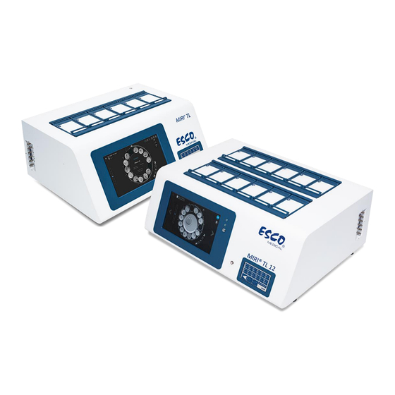
- Page 1 0123 USER MANUAL MIRI TL6 and MIRI TL12 ® ® multiroom IVF incubators Rev. 6.0 Revision Date 26/06/2024 Rx only...
-
Page 2: Copyright Information
Esco Medical Technologies, UAB Gamybos g. 2 • Ramuciai, Kauno r., 54468 Lithuania Tel +370 37 470 000 www.esco-medical.com • support-medical@escolifesciences.com For Technical Service, contact: Europe Esco Medical Technologies, UAB Gamybos g. 2 • Ramuciai, Kauno r., 54468 Lithuania Tel +370 37 470 000 www.esco-medical.com •... - Page 3 If the medical device is delivered in good physical condition but does not operate within specifications, or if there are any other problems not caused by shipping damage, please contact your local sales representative or Esco Medical Technologies, UAB immediately. Standard Terms and Conditions Refunds &...
- Page 4 Technologies, UAB ISO certification. Warranty and Product Support Esco Medical Technologies, UAB warrants this medical device to be free from defects in materials and workmanship under regular use and service for two (2) years from the original purchase date, provided the medical device is calibrated and maintained following this manual.
- Page 5 Warranty Disclaimer If your medical device is serviced and/or calibrated by someone other than Esco Medical Technologies, UAB and their representatives, please be advised that the original warranty covering your product becomes void when the tamper-resistant Quality Seal is removed or broken without proper factory authorization.
-
Page 6: Table Of Contents
Table of contents 1 How to use this manual .......................... 11 2 Safety warning ............................11 3 Intended purpose/use ..........................12 4 About the product ............................ 12 5 Transport, Storage and Disposal ......................14 5.1 Transportation requirements ..................... 14 5.2 Storage and operation environment requirements ............15 5.2.1 Storage requirements ...................... - Page 7 13.5.5 UV-C Light sub-menu ......................42 14 Alarms ................................ 42 14.1 Temperature alarms ........................43 14.2 Gas concentration alarms ......................44 14.2.1 CO alarms ..........................44 14.2.2 O alarms ..........................45 14.3 Gas pressure alarms ........................46 14.3.1 CO pressure alarm ......................46 14.3.2 N pressure alarm .........................
- Page 8 21 CultureCoin ............................84 ® 22 The MIRI TL multiroom IVF incubators Viewer’s Software ..........86 ® 23 Cleaning instructions ........................... 86 23.1 Consideration about a sterile device ..................86 23.2 Cleaning procedure recommended by the manufacturer ..........87 23.3 Cleaning procedure recommended by the manufacturer ..........88 24 Humidification ............................
- Page 9 36.5 Voltage supply ..........................106 36.6 CO gas concentration check ....................107 36.7 O gas concentration check ..................... 107 36.8 Temperature check: Chamber bottoms ................108 36.9 Temperature check: Chamber lids ..................108 36.10 6-hour stability test ........................ 109 36.11 Cleaning ............................110 36.12 Test documentation form .....................
- Page 10 39 The Installation guide ........................121 39.1 Responsibilities ........................... 121 39.2 Before installation ........................122 39.3 Preparing for installation ......................122 39.4 Bring the following to the installation site ............... 123 39.5 Installation procedure at the site ..................123 39.6 User training ..........................123 39.7 After the installation .........................
-
Page 11: How To Use This Manual
1 How to use this manual The manual is designed to be read by sections and not ideally from cover to cover. It means that if the manual is read from start to finish, there will be some repetition and overlap. -
Page 12: Intended Purpose/Use
The device use is limited up to six days (199 hours), covering the time from post-fertilization to day 6 of the development. 4 About the product The Esco Medical MIRI TL family`s multiroom IVF incubator are a CO incubators ®... - Page 13 validation purposes, each chamber has a PT-1000 sensor built in. The circuitry is separated from the device's electronics so it remains a truly separate validation system. The multiroom IVF incubator has to be supplied with 100% CO and 100% N in order to be able to control the CO and O...
-
Page 14: Transport, Storage And Disposal
® equipment that, once installed and placed into service, is not intended to be moved from one place to another. With Esco Medical MIRI TL family’s multiroom IVF incubators could work only ® individuals who have formal education in a relevant field of healthcare or medical discipline. -
Page 15: Storage And Operation Environment Requirements
A visual inspection should be done if there is any damage. If no damage is found, the MIRI TL6 or MIRI TL12 multiroom IVF incubator can be prepared for transport. ® ® These labels should be glued on the box: •... -
Page 16: Supplied Service Parts And Accessories
The device may have been used for treating and processing infectious substances. Therefore, the device and device components may be contaminated. Device must be disinfected or decontaminated prior to disposal. The device contains reusable materials. All components (except for the VOC/HEPA and HEPA filters) can be discarded as electrical waste after cleaning and disinfection. -
Page 17: Safety Symbols And Labels
7 Safety symbols and labels There are several user labels on the surface of the MIRI TL6 and MIRI TL12 multiroom ® ® IVF incubators to guide the user. User labels are shown below. Table 7.1 Packing box and electrical safety labels Description Image Packing box label for the MIRI... - Page 18 Table 7.2 Device label Description Image 1. Model. 2. Mains power rating. 3. CE mark. 4. Not protected against the ingress of water. 5. Manufacturer’s address and country of origin. 6. View instructions for use. 7. Temperature limit. 8. Rx only. 9.
- Page 19 Description Image BNC pH Alarm port Chamber numbers are indicated on the top corner of the lid with a label Maximum pressure 0.8 bar VOC/HEPA filter Ethernet TL on/off PT 1000 validation sensors Gas sample ports The connected external device to signal input/output connections should be compliant with the appropriate safety standard for medical equipment EN 60601-1.
-
Page 20: Important Safety Instructions And Warnings
® 8 Important safety instructions and warnings 8.1 Before installation 1. Do not use the product if the package is damaged. Contact Esco Medical Technologies, UAB or the local representative. 2. Read the user manual thoroughly before use. 3. Always keep these instructions easily accessible near the device. -
Page 21: Post Installation
– 8.70 PSI). 11. Never use any other filters except those provided by Esco Medical Technologies, UAB. Otherwise, the warranty will be void. 12. Do not use the device without a proper Esco Medical Technologies, UAB VOC/HEPA filter attached. 9 Getting started... -
Page 22: Mains Connection
12. After a burn-in phase of 24 hours, the device is ready for use IF the testing is successful. Clean and disinfect the device before use. It is not delivered sterile or in a clinically acceptable cleanliness state. Refer to the "23 Cleaning instructions" section of the User Manual for the manufacturer's recommended guidelines! 10 Mains connection The MIRI... -
Page 23: Voc/Hepa Filter
inlet should be connected to a 100% concentration of CO . CO control in the chamber is available in the range from 2.9% to 9.9% in both MIRI TL6 and MIRI TL12 multiroom ® ® IVF incubators. inlet should be connected to a 100% concentration N if low oxygen conditions are required. -
Page 24: Installation Of A New Filter Capsule
VOCs can also occur in medical gases, such as CO and N . It is essential to use in-line VOC filters to prevent these fumes from entering your multiroom IVF incubators for your medical gasses. Unexpected sources of VOCs are commonly found in IVF labs. These can include cleaning agents, perfumes, cabinetry, grease on the wheels of equipment and sources in HVAC equipment. -
Page 25: User Interface
Figure 12.1 The flow arrow on the MIRI TL6 and MIRI TL12 multiroom IVF incubators ® ® Then, simultaneously press both angle fittings (using both hands) into the holes till they snap into place (see Figure 12.2). The last 4 mm step should feel stiff. Figure 12.2 VOC/HEPA filter insertion and removal procedure Figure 12.3 Correctly installed VOC/HEPA filter A VOC/HEPA filter that has been installed incorrectly may cause gas leakage... -
Page 26: Activating The Heat And Gas Controls
User interface handles daily used functions and more advanced adjustments that might be made to the device. The main keys and their purpose are presented in table 13.1. Table 13.1 The main keys and their purpose Description Image ON/OFF keys It is located in the REAR of the device. - Page 27 Figure 13.2 Loading view Soon after system activation, the main display will show the following parameters: • Chambers 1 – 6 bottom and lid temperatures (only in the MIRI TL6 model). ® • Chambers 1 – 12 bottom and lid temperatures (only in the MIRI TL12 model).
-
Page 28: Temperature Setpoint
Figure 13.5 The second main display The second display shows temperature, CO and O setpoint values. If the O regulation is turned off, the display will show "OFF". Figure 13.6 The second main display Exit back to the main display by pressing the (▷) button. 13.2 Temperature setpoint The MIRI TL6 multiroom IVF incubator user interface images will be used as... - Page 29 For more information about multiple temperature setpoints, please read “13.5.4 Temperature Setpoint sub-menu” section below. To change the temperature setpoint, please follow these instructions: 1. In the main display, press the "Setpoint" button: Figure 13.7 Main display view in the MIRI TL6 multiroom IVF incubator ®...
- Page 30 To choose the chamber for which the setpoint value should be stated, press the button with the corresponding number. Figure 13.9 Chamber setpoints view in the MIRI TL6 multiroom IVF incubator ® 4. Use arrow up and down buttons to set the value: the arrow "DOWN" decreases the value, the arrow "UP"...
-
Page 31: Co Setpoint
13.3 CO setpoint The MIRI TL6 multiroom IVF incubator user interface images will be used as ® an example for all the CO setpoints. The CO setpoint can be adjusted in the range from 2.9% to 9.9% in both MIRI TL6 and ®... -
Page 32: O 2 Setpoint
Figure 13.13 Gas setpoint view in the MIRI TL6 multiroom IVF incubator ® When the desired value is set, press the "EXIT" button. The value will be saved automatically. Exit back to the main display by pressing the (▷) button. 13.4 O setpoint The MIRI... - Page 33 Figure 13.15 Setpoint page view in the MIRI TL6 multiroom IVF incubator ® 3. Use arrow up and down buttons to set the value: the arrow "DOWN" decreases the value, the arrow "UP" increases the value. One-click changes the value by 0.1%. Figure 13.16 Gas setpoint view in the MIRI TL6 multiroom IVF incubator ®...
-
Page 34: System Menu
13.5 System menu In the main display, press the "Menu" button. The main menu consists of 5 sub-menu applications: "Calibration", "CO Setup", "O Setup", "Temperature Setpoint", "UV-C Light". Figure 13.17 System menu view in the MIRI TL6 and MIRI TL12 multiroom IVF incubators ®... -
Page 35: Temperature Calibration
13.5.1.1 Temperature calibration Temperature calibration in the MIRI TL6 multiroom IVF incubator consists of 12 ® calibration zones. Figure 13.19 12 calibration zones in the MIRI TL6 multiroom IVF incubator ® Each chamber has two internal temperature sensors. One in the chamber lid and another in the chamber’s bottom. - Page 36 Figure 13.21 Temperature calibration zones for Chambers 1-6 in the MIRI TL12 multiroom IVF ® incubator Figure 13.22 Temperature calibration zones for Chambers 7-12 in the MIRI TL12 multiroom IVF ® incubator In the MIRI TL12 multiroom IVF incubator, each of the 12 chambers consist of "UP" and ®...
- Page 37 Example – how to calibrate temperature: The temperature has to be measured with a suitable and calibrated device. With a high- quality thermometer, it has been determined that T1 is 37.4 °C. Calibrate and adjust the temperature by pushing (+) or (-) keys. Adjust the temperature by pressing the (+) key 4 times when T1 is chosen.
- Page 38 Adjust the calibration to the desired concentration by pressing the “UP” and „DOWN“ buttons. In this case, the goal is to adjust CO gas concentration to 6.4%. Press the “UP” button so that thedisplay shows 6.0, 6.1, 6.2, 6.3 and 6.4%. The new value is now stored, and the CO sensor calibration has been completed.
-
Page 39: Co Setup Sub-Menu
5.3%. By pressing the "UP" button three times, it will take time to change the display's O concentration value, but the offset value will change immediately. By following this value, the user can see how much the O calibration value changed without delay. -
Page 40: O 2 Setup Sub-Menu
13.5.3 O Setup sub-menu Press the “O Setup” button in the main menu view. The user can activate or deactivate the O regulation. If the O regulation is activated, the setpoint value must be set. Figure 13.26 CO Setup sub-menu view in the MIRI TL6 and MIRI TL12 multiroom IVF incubator ®... -
Page 41: Temperature Setpoint Sub-Menu
13.5.4 Temperature Setpoint sub-menu Choose temperature setpoint settings according to the desired working conditions. If "Multi Temp SP" is "ON", it means that temperature values are individual in each chamber. If "Multi Temp SP" is "OFF", it means that temperature values are the same in all chambers. -
Page 42: Uv-C Light Sub-Menu
13.5.5 UV-C Light sub-menu Press the “UV-C Light” button in the main menu view. Figure 13.28 UV-C Light regulation in the MIRI TL6 and MIRI TL12 multiroom IVF incubator ® ® The default status for the UVC light is "ON". The UV-C light will automatically switch off when the device is turned off. -
Page 43: Temperature Alarms
Make sure that the ambient sound pressure level does not exceed 62 dB(A) because the user will not hear the alarm! The MIRI TL6 multiroom IVF incubator user interface images will be used as ® an example for all the alarms. 14.1 Temperature alarms All 6 chambers in the MIRI TL6 multiroom IVF incubator and 12 chambers in the MIRI... -
Page 44: Gas Concentration Alarms
If the mute key is pressed, the display will still show a red value, and the sound will be muted for 5 minutes until the audio alarm goes off again. The mute alarm key will still show the alarm condition by blinking red when the alarm is muted. Please refer to the "30 Emergency procedures"... -
Page 45: O 2 Alarms
Figure 14.5 Low CO concentration alarm view on the main display in the MIRI TL6 multiroom IVF ® incubator If the mute key is pressed, the display will still show a red value, and the sound will be muted for 5 minutes until the audio alarm goes off again. The mute alarm key will still show the alarm condition by blinking red when the alarm is muted. -
Page 46: Gas Pressure Alarms
muted for 5 minutes until the audio alarm goes off again. The mute alarm key will still show the alarm condition by blinking red when the alarm is muted. Please refer to the “30 Emergency procedures" section of the User Manual on how to behave when there is an O concentration alarm. -
Page 47: Alarm Uv-C Light
The user should consult the distributor for further guidance or service inspection. The "S. UV" will disappear only when the UV-C light will be working again. Please contact your Esco Medical distributor for more details. 14.5 Multiple alarms In the picture below, the temperature is too high in the T1 zone, the CO... -
Page 48: Loss Of Power Alarm
Figure 14.10 Multiple alarm view on the main display in the MIRI TL6 multiroom IVF incubator ® When there are multiple affected parameters, all of them will appear red in the display. If the mute key is pressed, the display will show a red value and the sound will be muted for 5 minutes until the audio alarm goes off again. -
Page 49: Summary Of The Alarms
14.7 Summary of the alarms In the table below, there is a list of every possible alarm in the MIRI TL family’s ® multiroom IVF incubators. Table 14.1 Every possible alarm in the MIRI TL family’s multiroom IVF incubators ® How it is Alarm Alarm... -
Page 50: Alarm Verification
14.8 Alarm verification In the table below, there is a list of how and when to verify the functionality of the alarm system. Table 14.2 Alarm verification in the MIRI TL family’s multiroom IVF incubators ® Alarm name How to verify an alarm When to verify an alarm Decrease the setpoint value by 3.0 °C from High-temperature alarm... - Page 51 Figure 15.2 Temperature zones in the MIRI TL12 multiroom IVF incubator ® Each area can be calibrated separately, using the item corresponding to the respective area in the menu. These items are placed in the MIRI TL6 multiroom IVF incubator menu, and they are ®...
- Page 52 To calibrate temperature in a particular area, please find the corresponding sensor name and adjust it according to the measurement taken using a high-precision thermometer. Temperature calibration is done by adjusting the Tx (where x is the sensor number) according to the measurement done on the spot relevant to the dish placement.
-
Page 53: Pressure
Calibration value change procedure should only be done with a calibrated device and by a trained user or the technician, according to specific measurements. 16 Pressure 16.1 CO gas pressure The CO pressure can be seen in the main display and the “CO Setup sub-menu”... -
Page 54: Gas Pressure
16.2 N gas pressure The N pressure can be seen in the main display and the “O Setup sub-menu”. Figure 16.3 Main display view in the MIRI TL6 multiroom IVF incubator ® Figure 16.4 CO Setup sub-menu view in the MIRI TL6 and MIRI TL12 multiroom IVF incubator ®... -
Page 55: Ph Measuring
The current MIRI TL6 multiroom IVF incubator firmware version is 1.05 for Master PCB ® and 1.04 for Slave PCB. The current MIRI TL12 multiroom IVF incubator firmware ® version is 1.08 for both Master and Slave PCB. 18 pH measuring Validating the pH of culture media should be a standard procedure. - Page 56 For calibration, at least two buffers are needed. However, we recommended using 3 buffers. One of the buffers should have a pH of 7. Any other pH buffer can be used as the user's buffer levels can be set in the calibration dialogue window. If only one or two buffers are available, the system can still be used but with reduced accuracy.
-
Page 57: Cybersecurity
TL12 multiroom IVF incubators must be connected to a network ® ® using equipment provided by Esco Medical Technologies, UAB. The connection procedure should be completed according to the provided schemes: Figure 19.1 MIRI TL family’s multiroom incubator’s connection scheme without the incorporated ®... - Page 58 Figure 19.2 MIRI TL family’s multiroom incubator’s connection scheme with the incorporated server ® and its components Compromised cybersecurity has risks related to the functions of the MIRI TL family’s ® multiroom IVF incubators: • Embryo time-lapse function ceasing to work. •...
-
Page 59: Screen Functions
MIRI TL family’s multiroom incubator should be disconnected ® from the network and the incident should be reported to the Esco Medical Technical support as soon as possible. Further guidance for diagnosis and troubleshooting should be followed. 20 Screen functions The screen works as the user interface for the time-lapse functions, the data-logging functions, alarm overview and the pH measuring function. - Page 60 Figure 20.2 The MIRI TL12 multiroom IVF incubator’s line altering switch and an active Line 1 ® Figure 20.3 Line change indication overlay in the main screen of the MIRI TL12 multiroom IVF ® incubator 2. When Line 2 is selected, the according green light lights up. Also, the Line change is indicated on the main screen by an overlay that displays “2”...
- Page 61 Figure 20.4 The MIRI TL12 multiroom IVF incubator’s line altering switch and an active Line 1 ® Figure 20.5 Line change indication overlay in the main screen of the MIRI TL12 multiroom IVF ® incubator Unauthorized access to the laboratory should be controlled! MIRI TL family`s multiroom IVF incubators User Manual Rev.
-
Page 62: The Main Screen
20.1 The main screen The main screen has an overview of the 6 chambers, showing their current bottom temperature and lid temperature. The circle shows the status of a time-lapse: is it active or inactive. If it is active, the time count will run on the screen. The MIRI TL6 multiroom IVF incubator user interface images will be used as ®... -
Page 63: Starting A Time-Lapse
Figure 20.4 Time-lapse calibrating view If the time-lapse is paused, the system will indicate "Suspended". Figure 20.5 Suspended time-lapse view A time-lapse may be suspended if, for instance, the dish is removed for a culture media change, manual observation or manipulation of the embryo. 20.1.1 Starting a time-lapse When the rectangle of an empty chamber in the main view is pressed, a time-lapse dialogue window will open. - Page 64 Figure 20.6 Patient selection main window view The 6 square icons on the top left side in the display indicate chamber number. Select the correct patient from the list. Figure 20.7 Test patient selection view If no patient is sent from the MIRI TL6 or MIRI TL12 multiroom IVF incubator Viewer’s ®...
- Page 65 If the required network connection is interrupted, the following screen will appear: Figure 20.9 Network connection interruption view When the correct patient has been selected, the active positions in the CultureCoin (the ® wells that will contain an embryo) must be selected. Positions 1 – 14 represent the 14 wells on the CultureCoin dish.
-
Page 66: Calibration Processes
Before starting time-lapse, it is essential to place the CultureCoin in the chamber ® properly. To ensure the correct position of the CultureCoin (so that the camera can ® identify all the wells), place the CultureCoin in its place and secure its position by ®... - Page 67 section of the User Manual below). In this case, the MIRI TL6 or MIRI TL12 multiroom ® ® IVF incubators should find the correct camera positions automatically. During the calibration process, there will be an indication in the middle area that the calibration process is active.
-
Page 68: Chamber View
Well that is marked in yellow colour (Interpolated) means that the calibration data of position are calculated based on calibration information around the exact position. For example, if 1 and 3 wells were calibrated, to calibrate 2 well, an average of Z (focus) are taken from 1st and 3 wells. - Page 69 A time-lapse can be suspended if the dish needs to be removed to make culture media changes or perform a manual observation with a microscope. When the dish is put back, the time-lapse can be resumed so that the final result will be one continuous film. Resuming the time-lapse will initiate automatic calibration as the removal of the dish may cause parameters to shift.
-
Page 70: Settings
Figure 20.17 Maximized time-lapse position view Scrolling through the 6 chambers is possible using the arrow keys "LEFT" and "RIGHT." The circled left arrow in the top left-hand corner will take you back to the main view. If no time-lapse is running in the chamber, the screen will indicate that the chamber is empty. -
Page 71: Manual Calibration Of The Well Position
Figure 20.19 Cycle and focal planes settings screen Press buttons corresponding to the desired choices. Cycle times cannot be set when a time-lapse has started. End all time-lapses to adjust the cycle time. Figure 20.20 Changes are disabled while time-lapses are running 20.1.5 Manual calibration of the well position If the automatic calibration process fails, the LiveView mode might be used for manual adjustments and calibration. - Page 72 As the live view function will allocate the camera system to a specific position, any running time-lapses will be suspended. If a time-lapse is running, a confirmation dialogue will be shown. Figure 20.21 Confirmation dialogue view Figure 20.22 Suspended time-lapses view The black background indicates that there is no active time-lapse running in the chamber.
- Page 73 It is possible to navigate among the chambers and the 14 positions. The system will indicate such movement. Buttons in the top right corner offer the selection of the motor control, a square selection tool and an exposure time. Press the microscope button marked red on the MIRI® TL6 or MIRI® TL12 multiroom IVF incubator screen to enter LiveView mode.
- Page 74 Figure 20.26 Example of a correct well position in the camera view screen Figure 20.27 Example of an incorrect well position in the camera view screen If necessary, adjust the X-axis position with the "LEFT" or/and "RIGHT" arrows under the "Motor"...
- Page 75 Figure 20.28 Well position adjustment device in the X-axis Make sure that your well/embryo is well focused (has good focus). If necessary, adjust the Z-axis position with the "UP" or/and "DOWN" arrows under the "Motor" icon (located in the upper right corner of the screen). Figure 20.29 Well position adjustment device in the Z-axis MIRI TL family`s multiroom IVF incubators User Manual Rev.
- Page 76 Make sure that the well is inside the marked square limit, as shown below. Figure 20.30 Well position inside the marked square limit If the well position is out of the limit mark square, it could result in cropped images during the time-lapse. It could cause a system error, and the images of the well would not be taken.
-
Page 77: Alarms
When the correct position and the desired focus are found and the set button is pressed, the system confirms the user's calibration. Figure 20.32 Correctly adjusted well’s view Manually overriding automatic system features should be done only when the system repeatedly fails to find the correct calibration. Since the user manually controls the motors in the LiveView, it is possible to move the motors out of bounds and trigger mechanical limit switches. - Page 78 Figure 20.34 Lid opening alarm view Clear the alarm by pressing on the area – it will take you to the chamber view. Then either end the time-lapse, suspend, recalibrate or just confirm that the patient is still there. Figure 20.35 Chamber view after opening a lid The system will continue to generate time-lapse images after the lid is opened.
- Page 79 Figure 20.36 Temperature alarm screen view Remove the dish immediately if temperature conditions become dangerous for the embryos. The chambers are entirely separate, so the dish can be safely moved to another position if the temperature in that particular chamber is stable. Remember to end an old time-lapse and start the new at the changed position.
- Page 80 All incubation functions have level alarms indicated in the image by the relevant button turning red. All of the alarms can be seen in the alarm view, which displays the alarm history. concentration alarm view is shown in the picture below: Figure 20.38 CO concentration alarm view pressure alarm view is shown in the picture below:...
-
Page 81: Data-Logging Temperature View
Full HDD (transfer data to an external drive or connect to the server) memory alarm view is shown in the picture below: Figure 20.40 HDD full memory alert view 20.1.7 Data-logging temperature view Pressing the temperature button will change the view to a temperature data graph view. Figure 20.41 Temperature data graph view The history view allows seeing temperature data graphs. -
Page 82: Data-Logging Co 2 View
20.1.8 Data-logging CO view By pressing the "CO2" button, the view will change to the CO data graph view. The CO "Setpoint", "Concentration", "Flow", and "Pressure" graphs can be toggled on/off by pressing on them at the top of the display view. The time period and zoom-in functions are the same as in the temperature view. -
Page 83: Data-Logging Alarm View
20.1.10 Data-logging alarm view By pressing the alarm bell, the alarm view opens up. The alarm view depicts all the parameters and any alarm statuses in a quick graphical overview. A red block represents each alarm – the longer the alarm lasts, the more that block increases in size. Figure 20.44 Alarm data view The "Lid"... -
Page 84: Culturecoin
21 CultureCoin ® The only dish used with MIRI TL6 and MIRI TL12 multiroom IVF incubators is the ® ® CultureCoin . The bottom of MIRI TL6 and MIRI TL12 multiroom IVF incubators ® ® ® chambers are shaped to fit the contour of the dish. There is only one way it can be put in the chamber, as the dish is not a perfect circle and has a flat side that makes it impossible to fit the dish in the chamber the wrong way. - Page 85 Each of the 14 wells is filled with approximately 25 µl culture medium. The washing wells can also be filled (approximately with 23 µl of liquid), but it is not a requirement. The embryo is placed at the bottom of the culturing area. Figure 21.3 Embryo Placement in detail on the 300µm optically clear area The process of locating the correct well is sensitive to errors.
-
Page 86: The Miri ® Tl Multiroom Ivf Incubators Viewer's Software
Figure 21.4 The culture wells are covered with a mineral oil layer, and the lid is put on A large reservoir outside the culturing area can be used for pH validation (please look at Figure 21.1). The reservoir can be closed with a gas permeable silicone plug which will stop evaporation. -
Page 87: Cleaning Procedure Recommended By The Manufacturer
The design features intended to provide cleanliness include: • A circulated air system. • External 0.22µm and internal 0.2µm HEPA filters which clean the incoming gas. • A VOC/HEPA filter, which continually cleans the air inside the system. • A chamber with sealed edges that can be cleaned. •... -
Page 88: Cleaning Procedure Recommended By The Manufacturer
23.3 Cleaning procedure recommended by the manufacturer Disinfection of the device (with no embryos inside) Wearing gloves and GLP (good laboratory practice) techniques are essential to the successful disinfection of the device. Proceed with the following steps (this procedure has been demonstrated during the on- site training program as part of the installation protocol): 1. -
Page 89: Temperature Validation
Temperature conditions in the chambers can be continuously logged through the external connectors on the device's side without compromising its performance. Any logging system that uses standard PT-1000 sensors may be used. Esco Medical Technologies, UAB can supply an external logging system (MIRI -GA) for ®... -
Page 90: Gas Concentration Validation
26 Gas concentration validation Gas concentration in each chamber of the MIRI TL6 or MIRI TL12 multiroom IVF ® ® incubator may be validated by taking a gas sample from one of the 6 (MIRI TL6 model) ® or 12 (MIRI TL12 model) gas sample ports on the device's side, using a suitable gas ®... -
Page 91: Alarm Switch For An External System
Taking out a large sample volume may affect gas concentration. Make sure that the gas analyzer is calibrated before use. 27 Alarm switch for an external system The MIRI TL6 or MIRI TL12 multiroom IVF incubator is equipped with a 3.5 mm jack ®... -
Page 92: Writing Area On The Chamber Lids
through the system anymore. Figure 27.2 “Open circuit” alarm mode Whenever the MIRI TL family’s incubator’s power cord is disconnected from ® the power source, this switch will automatically indicate an alarm! It is an extra safety feature intended to alert the personnel in case of a power cut in the laboratory. -
Page 93: Emergency Procedures
where the MIRI TL6 or MIRI TL12 multiroom IVF incubator is used. The ® ® manufacturer recommends that the period between validations should be no longer than 14 days. 2. VOC/HEPA filters must be replaced every 3 months. 3. External and internal HEPA filters must be replaced yearly during annual maintenance. - Page 94 If multiple temperature alarms go off: • Remove the samples from the affected chamber. They can be relocated to any of the other chambers, which happens to be unoccupied. All chambers are separate so that the remaining ones will function normally; •...
-
Page 95: User Troubleshooting
31 User troubleshooting Table 31.1 Heating system Symptom Cause Action The device is switched off at the back Switch on the device or connect to No heating, the display is off or not connected to the power source the power source heating off, because,... - Page 96 N2 gas input 0.6 bar of N gas is applied Check the O setpoint. If the issue The actual gas concentration is higher persists, contact Esco Medical than the setpoint support Lid(s) are left open Close the lid(s) Poor O...
-
Page 97: Specifications
32 Specifications Table 32.1 MIRI TL6 multiroom IVF incubator’s specifications ® Technical specifications MIRI ® Overall dimensions (W x D x H) 805 x 590 x 375 mm Weight 60 kg Material Mild steel/Aluminum/PET/Stainless steel Dish type CultureCoin ® Power supply 115V 60Hz OR 230V 50Hz Power consumption 330 W... -
Page 98: Electromagnetic Compatibility
33 Electromagnetic compatibility Table 33.1 Electromagnetic emissions Guidance and manufacturer’s declaration – electromagnetic emissions The MIRI TL6 and MIRI TL12 multiroom IVF incubators are intended for use in the electromagnetic ® ® environment specified below. The customer or the user of the MIRI TL6 or MIRI TL12 multiroom IVF ®... - Page 99 Power frequency Power frequency magnetic fields (50/60 Hz) should be at levels characteristic magnetic field of a typical location in a typical commercial hospital IEC 61000-4-8 environment. Guidance and manufacturer’s declaration – electromagnetic immdevicey The MIRI TL6 and MIRI TL12 multiroom IVF incubators are intended for use in the electromagnetic ®...
- Page 100 Table 33.3 Recommended separation distances Recommended separation distances between portable and mobile RF communication equipment and the MIRI TL6 or MIRI TL12 multiroom IVF incubators ® ® The MIRI TL6 and MIRI TL12 multiroom IVF incubators are intended to be used in an electromagnetic ®...
-
Page 101: The Validation Guide
34 The Validation guide 34.1 Product release criteria The Esco Medical MIRI TL6 and MIRI TL12 multiroom IVF incubators undergo strict ® ® quality and performance testing before being released for sale. 34.1.1 Performance Each component used in the MIRI... -
Page 102: Visual Inspection
In the following, we describe these tests and the equipment necessary to perform them. A test documentation form is also provided. A copy must be provided to Esco Medical Technologies, UAB for internal device tracking and device history record. -
Page 103: Mandatory Equipment
35.1 Mandatory equipment All equipment must be of high quality and calibrated. • A thermometer with a suitable sensor for measuring in a droplet of media covered with Paraffin oil with a minimum resolution of 0.1 °C. • A thermometer with a suitable sensor for measuring on an aluminum surface with a minimum resolution of 0.1 °C. -
Page 104: About Co
Sample from the bottle near the bottom with the gas analyzer. PASS: CO concentration measured must be between 98.0% – 100%. Use of CO gas with moisture will damage the flow sensors. Moisture level must be verified on the gas manufacturer's certificate: only 0.0 ppm v/v Max is permissible. -
Page 105: Gas Supply N
• Total Sulphur (as S) 0.1 ppm v/v max. 36.2 Gas supply N For the regulation and maintenance of the correct O concentration levels in the MIRI ® TL6 or MIRI TL12 multiroom IVF incubator chambers, the device must be connected to ®... -
Page 106: Co Gas Pressure Check
• Oxygen (O ) 0.5 ppm. • Water (H O) 0.5 ppm. 36.3 CO gas pressure check The MIRI TL6 and MIRI TL12 multiroom IVF incubator require a pressure of 0.4 – 0.6 ® ® bar (5.80 – 8.70 PSI) on the input CO gas line. - Page 107 PASS: 230V ± 10.0% 115V ± 10.0% 36.6 CO gas concentration check The CO gas concentration is checked for deviation. The gas sample port on the side of the device is used. Use sample port-6 for validation. Remember not to open any lid at least 15 min before starting the test nor during the testing itself.
- Page 108 36.8 Temperature check: Chamber bottoms The first part of the temperature check is performed using a thermometer with a sensor suitable for measuring temperature in a droplet of media covered with Paraffin oil, with a resolution of 0.1 °C as a minimum. At least 6 dishes are prepared for MIRI TL6 and 12 for MIRI TL12 multiroom IVF...
- Page 109 If the N is not available, the test can be done without it. Make sure that the Esco Medical data logger software is running. Check that parameters are logged and give a meaningful reading. Let the device run without interfering for at least 6 hours. Analyse the results on the graphs.
- Page 110 Inspect the device for physical signs of dirt or dust. The device should look generally tidy. 36.12 Test documentation form The "Installation report" form must be completed with the tests-passed status filled by installation personnel and submitted to Esco Medical Technologies, UAB before the device is taken into clinical use. 36.13 Recommended additional testing 36.13.1 A VOC meter...
-
Page 111: Clinical Use
37 Clinical use Congratulations! Your device is now ready for clinical use with the validation tests completed and the test report submitted to Esco Medical Technologies, UAB. It is necessary to monitor the performance of the device continually. Use the below scheme for in-use validation. - Page 112 37.2 CO gas concentration check The CO gas concentration is checked for deviations. The gas sample port on the side of the device is used for this. Use sample port-6 for validation. It is essential to have a high- precision gas analyzer for CO and O available to do the test.
- Page 113 IVF incubator will not be affected, as the gas in the chamber is not under pressure, and the reading is just an artifact based on unsuitable measuring equipment. Contact Esco Medical Technologies, UAB or the local distributor for further guidance.
- Page 114 User validation should be done as a minimum according to instructions given in the "34 The Validation guide" section. If problems are encountered, contact Esco Medical Technologies, UAB or your local representative. However, to sustain the high-performance level and avoid system errors, the owner is responsible for having a certified technician who performs components replacements according to table 38.1.
- Page 115 IVF incubator must be replaced every 3 months. Please follow these safety precautions when changing the VOC filter: • Always use the original filter (contact Esco Medical Technologies, UAB or your local distributor for more details or ordering). • Change filter every 3 months.
- Page 116 CO regulation system. Please follow these safety precautions when changing the filter: • Always use the original filter (contact Esco Medical Technologies, UAB or your local distributor for more details or ordering). • Change the filter once every year.
- Page 117 This sensor's lifetime is more than 6 years, but for safety reasons, Esco Medical Technologies, UAB recommends the sensor to be replaced once every 4-years. Please follow these safety precautions when changing the sensor: •...
- Page 118 Always power the device off before removing any cover. Please follow these safety precautions when changing the UV-C light: • Always use an original UV-C light bulb (contact Esco Medical Technologies, UAB or your local distributor for more details or ordering).
- Page 119 Please follow these safety precautions when changing the internal gas pump: • Always use an original gas pump (contact Esco Medical Technologies, UAB or your local distributor for more details or ordering). • Change the gas pump within 2 years from the date of installation.
-
Page 120: Pressure Regulators
Please follow these safety precautions when changing gas lines: • Always use original gas lines (contact Esco Medical Technologies, UAB or your local distributor for more details or ordering). • Failure to change the gas lines may cause slow recovery times or breakdowns. - Page 121 Please refer to the service manual for instructions on how to update the firmware. 38.14 Software update If Esco Medical Technologies, UAB has released a newer version of the software, it should be installed on the MIRI TL6 or MIRI TL12 multiroom IVF incubator during the yearly ®...
-
Page 122: Preparing For Installation
Experienced service technicians or embryologists conduct training to ensure that the installation personnel clearly understand the device's functions, performance, testing, and maintenance. Installation personnel must be updated regarding alterations or additions to this document and the "Installation report" form. 39.2 Before installation 2 –... - Page 123 39.4 Bring the following to the installation site • "Installation report" form; • Service manual for the MIRI TL6 or MIRI TL12 multiroom IVF incubator; ® ® • Updated service tool kit; • Memory stick with the latest released firmware & software; •...
- Page 124 When the installation trip is finished, a copy of the original "Installation report" form must be sent to Esco Medical Technologies, UAB. It will be saved with the device records. According to the ISO procedure and Medical Device Directive, a paper copy of the completed and signed installation test form is stored in the unique device's device history record.
-
Page 125: Other Countries
In case of any serious incidents that have occurred in relation to the device should be reported to Esco Medical Technologies, UAB by contacts, written on the contact information page, and the Authorised Representative in which the user and/or patient is established.
Need help?
Do you have a question about the MIRI TL6 and is the answer not in the manual?
Questions and answers