
Subscribe to Our Youtube Channel
Related Manuals for Esco Medical Mini MIRI Dry


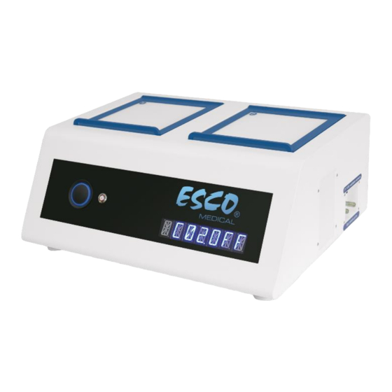
Summary of Contents for Esco Medical Mini MIRI Dry
- Page 1 CE 0088 USER MANUAL Mini MIRI Dry / Humidity Multiroom ® Incubators Rev. 2.0 Date revised 03.26.2021 Rx only...
- Page 2 Esco Medical Technologies, Ltd. Draugystės street 19 • Kaunas, Lithuania Tel +370 37 470 000 medical.escoglobal.com •support-medical@escoglobal.com For Technical Service, contact North America Esco Technologies, Inc. 903 Sheehy Drive, Suite F, Horsham, PA 19044, USA Tel 215-441-9661 • Fax 484-698-7757 www.escolifesciences.us •...
- Page 3 During the war- ranty period, Esco Medical will, at our option, either repair or replace a product that proves to be defective at no charge, provided you return the product (shipping, duty, Mini MIRI Dry/Humidity User Manual Rev.
- Page 4 This warranty is limited to repairing the instrument per Esco Medical's specifications. When you return an instrument to Esco Medical for service, repair or calibration, we rec- ommend shipment using the original shipping foam and container. If the original packing materials are not available, we recommend the following guide for repackaging: •...
- Page 5 In an event where the seal must be broken to gain internal access to the instrument, you must first contact Esco Medical Ltd. You will be required to provide us with the serial number for your instrument, as well as a valid reason for breaking the Quality Seal.
-
Page 6: Table Of Contents
Table of contents 1 How to use this manual .......................... 11 2 Safety warning ............................11 3 Indication for use............................11 4 About the product ............................ 12 5 Transport, Storage and Disposal ......................13 5.1 Transportation requirements ..................... 13 5.2 Storage and operation environment requirements............14 5.2.1 Storage requirements ...................... - Page 7 13.4.5 Service sub-menu ........................29 14 Installation with premixed gas ......................30 14.1 Installation procedure at the site .................... 30 14.2 User training ............................ 32 15 Alarms ................................ 33 15.1 Temperature alarms ........................33 15.2 Gas level alarms ..........................34 15.2.1 CO alarms ..........................
- Page 8 23.2 The Mini MIRI Humidity incubator ..................45 ® 24 Temperature validation ........................45 25 Gas level validation ..........................46 26 Alarm switch for an external system ..................... 46 27 Writing area on the compartment lids ..................47 28 Maintenance ............................48 29 Emergency Procedures........................
- Page 9 35.11 Cleaning ............................64 35.12 Test documentation form ......................65 35.13 Recommended additional testing ..................65 35.13.1 A VOC meter (only for Mini MIRI Dry model)............65 ® 35.13.2 A laser particle counter ....................65 36 Clinical use ..............................65 36.1 Temperature check ........................
- Page 10 38.4 Bring the following to the installation site ................77 38.5 Installation procedure at the site .................... 77 38.6 User training ............................ 78 38.7 After the installation ........................78 Mini MIRI Dry/Humidity User Manual Rev. 2.0 ®...
-
Page 11: How To Use This Manual
• If the equipment is used in a manner not specified by this manual, the protection provided by this equipment may be impaired. 3 Indication for use The Esco Medical Mini MIRI incubators are intended to be used to provide a stable culture envi- ®... -
Page 12: About The Product
The compartment's temperature will remain stable up to 1 °C (even when a lid is open for the 30s) and recover within 1 min after it is closed. The Esco Medical Mini MIRI incubators have 2 completely separate culture heat chambers. Each ®... -
Page 13: Transport, Storage And Disposal
Refer to section “16.4 The culture mode” for more detailed information. The incubator can be connected to a PC running the Esco Medical data logging software for long- term data logging and data storage. -
Page 14: Storage And Operation Environment Requirements
These labels should be glued on the box: • Label with the marked packing date • Label with the product name and serial number • Label with the country of origin • Warning labels “Fragile” and “Handle with care” 5.2 Storage and operation environment requirements 5.2.1 Storage requirements The device may only be store under the following conditions: •... -
Page 15: Accessories Supplied
• 1 pump box calibration tool (only for Mini MIRI Humidity model) ® • 1 USB stick containing Esco Medical Data logger software and a PDF version of the user manual • 1 medical grade power cord • 1 3,5 mm external alarm jack connector •... - Page 16 Table 7.2 Device labels Description Image 1. Model. 2. Mains power rating. 3. CE mark. 4. Not protected against the ingress of water. 5. Manufacturer’s address and country of origin. 6. View instruction for use. 7. Observe WEEE. 8. Upper limit of temperature. 9.
-
Page 17: Important Safety Instructions And Warnings
Figure 7.1 Compartment numbers 8 Important safety instructions and warnings 8.1 Before installation 1. Do not use the product if the package is damaged. Contact Esco Medical or the local repre- sentative. 2. Read the user manual thoroughly before use. -
Page 18: Post-Installation
0.4 – 0.6 bar (5.80 – 8.70 PSI). 11. Never use any other except Esco Medical filter. Otherwise, the warranty will be void. 12. Do not use the device without a proper Esco Medical VOC/HEPA filter attached. -
Page 19: Mains Connection
10 Mains connection Mini MIRI Dry and Mini MIRI Humidity incubators come with a detachable main power cord. ® ® The power cord is prepared for the country in which the unit is intended to be used. Do not defeat the safety purpose of the grounding-type plug! A grounding type plug has two blades and a third prong. -
Page 20: Hepa/Voc Filter (Not Available In The Us)
Always use a high-quality pressure regulator that can be set with the required precision for both gases. Figure 11.2 Pressure regulator Connect the CO gas to the CO inlet with a suitable silicone tube. Ensure the tube is fastened with a clip so that it does not accidentally loosen itself during sudden pressure fluctuation. -
Page 21: Installation Of New Filter Capsule (Only In The Mini Miri ® Dry Model)
High levels of VOCs (over 1 ppm) are toxic to embryos, resulting in poor embryo development and even probable failure to reach the blastocyst stage. VOC levels in the 0.5 ppm range will typically allow for acceptable blastocyst development and reasonable pregnancy rates but will result in a high percentage of miscarriages. -
Page 22: User Interface
Then, simultaneously press both angle fittings (using both hands) into the holes till they snap into place. The last 4 mm step should feel stiff. A filter element that is fitted incorrectly will cause the unit not to work not as intended. This is dangerous! The filter is removed by gently pulling it straight out using both hands. -
Page 23: Activating The Heat And Gas Controls
13.1 Activating the heat and gas controls Heat and gas control systems are activated using the “ON/OFF” switch in the rear. Soon after system activation, the main display will alternate the reading between the following 4 parameters: Temperature = Temperature in °C = CO Concentration in % Concentration in %... -
Page 24: Main Menu
If the use mode is Open Culture (no oil or Paraffin overlay culture), the device shall be set for that and will display: 13.4 Main menu Press the rotatory button – enter the menu. You can exit the menu by rotating the rotatory button (↺). Temperature is the first category when you enter the menu. -
Page 25: Temperature Sub-Menu
13.4.1 Temperature sub-menu Press the rotatory button on the temperature menu to enter the temperature sub-menu. Calibrate temperature by pressing the rotatory button and rotating it (↻) or (↺) to adjust. Move to the next sub-menu item with (↻) rotation or one step up with (↺) rotation. Example - how to calibrate the temperature: The temperature has to be measured with a suitable and calibrated device. - Page 26 Toggle CO regulation on/off by pressing the rotatory button and rotating it (↻) or (↺). The default status for the CO control is OFF. Move to the next CO sub-menu item with (↻) rotation or one step up with (↺) rotation. flow rate is shown (it cannot be adjusted): It shows the amount of CO gas put into the system while regulating.
-
Page 27: Sub-Menu
Rotate rotator button (↻) to adjust the CO calibration to the desired level by (↻) or (↺) rotation. In this case, we want to change to 6.4%. Rotate (↻) till the display shows 6.0, 6.1, 6.2, 6.3 and 6.4. When CO equals measured CO press the rotatory button. -
Page 28: Uv-C Light Sub-Menu (The Functionality Is Not Available In The Us)
It shows the amount of N gas put into the system while regulating. The volume is shown in li- ters/hour. It usually will fluctuate along with the O regulation. Move to the next O sub-menu item with (↻) rotation or one step up with (↺) rotation. internal pressure rate is shown (it cannot be adjusted on the incubator. -
Page 29: Service Sub-Menu
Press the rotatory button on the service menu to enter the service sub-menu. The display will show the currently installed firmware version: Ver 2.0 is only shown as an example. Consult Esco Medical or the local representative for the num- ber of the latest version. -
Page 30: Installation With Premixed Gas
When using the premixed gas mode, it is necessary to use a premixed gas with higher gradation than the setpoint. For example, if you need to achieve a 5% CO gas setpoint, pre- mixed gas should have 6% CO in its mixture. Then exit the menu by (↺) or press the rotatory button and hold it until the main menu does not appear. - Page 31 Figure 14.1 Premixed gas connections to the incubator Please read the “11 Gas connection” section in this manual above for more detailed gas connection requirements. Measure the gas concentration from the premixed gas bottle with a calibrated gas analyzer. The result of the measurement is significant for the set-up of the device and the correct operation.
-
Page 32: User Training
Press the rotatory button to enter the service sub-menu and rotate (↻) or (↺) to choose “PREMIX”. Press the rotatory button to select the premixed gas work mode. Then exit the menu by (↺) or press the rotatory button and hold it until the main menu does not appear. -
Page 33: Alarms
15 Alarms The display will show a red “A” and the affected parameter's status message on a single fault con- dition. An audio signal can be muted by pressing the alarm key once (toggled on/off for 5- minutes). There will be a red arrow that indicates if the alarm is triggered due to too high or too low values, and the audio on/off key will blink red: Figure 15.1 Alarm key which indicates the alarm condition The audio pattern is 3 short beeps followed by a 3-second pause. -
Page 34: Gas Level Alarms
If a temperature sensor malfunctions, it will be indicated by the following warning: It denotes that the sensor in compartment 2 has failed. As a safety precaution, the heating of the affected area will be switched off. 15.2 Gas level alarms 15.2.1 CO alarms The CO... -
Page 35: Gas Pressure Alarms
gas % is too low: gas % is too high: The display will lock-on the alarm condition and will stop alternating between the standard status messages. If the mute key is pressed, the display will shift to normal status and show the parame- ters for 5 minutes until the audio alarm comes back on again. -
Page 36: Multiple Alarms
“P” stands for pressure. The display will lock-on the alarm condition and will stop alternating between the standard status messages. If the mute key is pressed, the display will shift to normal status and show the parame- ters for 5 minutes until the audio alarm comes back on again. The mute alarm key will still show the alarm condition by blinking red while the alarm is muted. -
Page 37: Changing The Setpoints
16 Changing the setpoints 16.1 The temperature setpoint The temperature setpoint can be adjusted in the range between 24.9 °C to 40.0 °C. The default temperature setpoint is 37.0 °C. To change the temperature setpoint, follow these instructions: 1. When the display shows the current temperature: 2. -
Page 38: The Culture Mode
The default O setpoint is 5.0% To change the O gas concentration setpoint, follow these instructions: 1. When the display shows the O gas concentration: 2. Press the rotatory button and rotate (↻) or (↺) to adjust the setpoint. 3. After changing the value, press the rotatory key once more to save the value. If the display does not show the current temperature reading, rotatory button rotation (↻) or (↺) will toggle between the temperature, CO and mode readings. -
Page 39: Surface Temperatures And Measuring Temperature
(in 4 well dish). If the media stays longer without oil coverage, a high risk of media osmolality changes appears. If you have any questions or uncertainty, consult Esco Medical or your local representative before using open culture mode in the Mini MIRI Multiroom incubator. - Page 40 To calibrate the temperature in a particular area, please find the corresponding sensor name and adjust it according to a measurement taken using a high-precision thermometer. Temperature calibration is done by adjusting the Tx (where x is the sensor number) according to a measurement done on the spot relevant to the dish placement.
-
Page 41: Pressure
18 Pressure 18.1 CO gas pressure The CO pressure can be read out in the CO sub-menu: The CO pressure is shown in bar. External pressure must be between 0.4 – 0.6 bar (5.80 –8.70 PSI) at all times. It cannot be adjusted on the incubator; it must be done on the external gas regu- lator. -
Page 42: Safe Sense Function
In the menu, locate the Service sub-menu “SERV” and rotate the rotatory button (↻). The display will show the currently installed firmware version: Ver 2.0 is only shown as an example. Consult Esco Medical or the local representative for the num- ber of the latest version. -
Page 43: Manufacturer Recommended Cleaning Procedure
21.2 Manufacturer recommended cleaning procedure Always validate the cleaning procedures locally; for more guidance, consult your man- ufacturer or the distributor. The routine cleaning procedure is recommended for regular processing and maintenance. The combination of standard cleaning procedures and disinfection procedures is recommended for event-related concerns such as media spills, visual accumulation of soil and/or other evidence of contamination. -
Page 44: Heat Optimization Plates
Use only the correct type of heat optimization plates for your dishes. Figure 22.1 Heat optimization plate Never incubate without the plates in place and never use non-Esco Medical heating optimization plates. It may cause dangerous and unpredictable temperature conditions that may be harmful to the specimens. -
Page 45: The Mini Miri ® Humidity Incubator
In “Oil culture” mode, lid temperature is kept 0.2 – 0.3 °C above the temperature setpoint. In “Open culture” mode, lid temperature will be increased in 1.0 °C above the temperature setpoint. Please consult Esco Medical or your local representative before using “Open culture” mode in the Mini MIRI Dry incubator if you have any questions. -
Page 46: Gas Level Validation
25 Gas level validation Gas concentration in each compartment of Mini MIRI Dry or Mini MIRI Humidity incubator may ® ® be validated by taking a gas sample from one of the 2 gas sample ports on the unit's side, using a suitable gas analyzer. -
Page 47: Writing Area On The Compartment Lids
If a voltage source is attached, then the limitation is between 0 – 50V AC or DC. If there is no alarm, the switch within the unit will be in the “ON” position, as illustrated below. Figure 26.1 No alarm mode Whenever Mini MIRI Dry or Mini MIRI Humidity incubator goes into an alarm mode, the switch... -
Page 48: Maintenance
Figure 27.1 Area for patient information 28 Maintenance Mini MIRI Dry and Mini MIRI Humidity incubators are designed to be user-friendly. Reliable ® ® and safe operation of this equipment is based on the following conditions: 1. Correct calibration of temperature and gas level, using high-precision equipment in the in- tervals prescribed based on clinical practice at the laboratory, where Mini MIRI Dry or ®... - Page 49 • The CO concentration will remain within 1% of the setpoint for 30 minutes if the lids re- main closed. • If a longer time to turn the power back on is needed, it may be useful to cover the unit with insulating blankets to slow the temperature drop.
-
Page 50: User Troubleshooting
30 User Troubleshooting Table 30.1 Heating system Symptom Cause Action The unit is switched off at the back or Switch the device on or connect No heating, the display is off not connected to the power the power The temperature is more than 0.5 °C off the set temperature The setpoint for temperature is No heating... - Page 51 Please refer to the software installa- not correctly installed tion guide Table 30.5 Display Symptom Cause Action Contact your Esco Medical Distribu- Missing segment(s) in display Failure in the PCB tor to replace the PCB Table 30.6 Keyboard Symptom Cause...
-
Page 52: Specifications
31 Specifications Table 31.1 Mini MIRI Dry incubator specifications ® Technical specifications Mini MIRI ® Overall dimensions (WxDxH) 525 x 420 x 230 mm Weight 22 kg Material Mild steel / Aluminum / PET / Stainless steel Power supply 115V 60Hz OR 230V 50Hz Power consumption 90 W Temperature control range... -
Page 53: Electromagnetic Compatibility
32 Electromagnetic compatibility Table 32.1 Electromagnetic emissions Guidance and manufacturer’s declaration – electromagnetic emissions Mini MIRI Dry and Mini MIRI Humidity incubators are intended for use in the electromagnetic environ- ® ® ment specified below. The customer or the user of Mini MIRI Dry or Mini MIRI Humidity incubators should ®... - Page 54 Guidance and manufacturer’s declaration – electromagnetic immunity Mini MIRI Dry and Mini MIRI Humidity incubators are intended for use in the electromagnetic environ- ® ® ment specified below. The customer or the user of Mini MIRI Dry or Mini MIRI Humidity incubators should ®...
- Page 55 Table 32.3 Recommended separation distances Recommended separation distances between portable and mobile RF communication equipment and Mini MIRI Dry or Mini MIRI Humidity incubators ® ® Mini MIRI Dry or Mini MIRI Humidity incubators are intended to be used in an electromagnetic environ- ®...
-
Page 56: The Validation Guide
33 The Validation guide 33.1 Product release criteria The Esco Medical Mini MIRI Dry and Mini MIRI Humidity incubator undergo strict quality and ® ® performance testing before being released for sale. 33.1.1 Performance Each component used in Mini MIRI... -
Page 57: Cosmetic
34 Validation on-site Even though at Esco Medical, we strive to do the most comprehensive tests before the device is shipped to the customer, there is no way to be sure that everything is still OK at the location when the device is set up. -
Page 58: Recommended Additional Equipment
34.2 Recommended additional equipment All equipment must be of high quality and calibrated. • A VOC meter able to measure the most common volatile organic compounds at least at the ppm-level. • A sample should be taken just above Mini MIRI Dry or Mini MIRI Humidity incubator ®... -
Page 59: Gas Supply N
Bulk liquid carbon dioxide is commonly maintained as a refrigerated liquid and vapor at pressures between 1,230 kPa (approx. 12 bar) and 2,557 kPa (approx. 25 bar). Carbon dioxide may also exist as a white opaque solid with a temperature of -78.5 °C under atmospheric pressure. A high concentration of carbon dioxide (10.0% or more) can asphyxiate quickly with- out warning with no possibility of self–rescue regardless of the oxygen concentration. -
Page 60: About N
The use of N gas with moisture will damage the flow sensors. Moisture level must be verified on the gas manufacturer's certificate: only 0.0 ppm v/v Max is permissible. 35.2.1 About N Nitrogen makes up a significant portion of the earth's atmosphere with 78.08% by volume. Nitro- gen is a colorless, odorless, tasteless, non-toxic, and almost inert gas. -
Page 61: Voltage Supply
For safety, this unit has a built-in digital gas pressure sensor that monitors the incoming gas pres- sure and alerts the User if any drop is detected. Remove the inlet gas line for the N gas. Attach the gas line to the gas pressure measuring device. PASS: The value must be 0.4 –... -
Page 62: Temperature Check: Compartment Bottoms
Remember not to open any lid at least 10 min before starting the test nor during the testing itself. Hook-up the gas analyzer inlet tube to the sample port. Make sure that the fit is perfect and that no air can enter or exit the system. The gas analyzer must have a gas return port connected to the incubator (i.e., another compart- ment). -
Page 63: Temperature Check: Compartment Lids
If calibration is needed, please refer to the "13.4.1 Temperature sub-menu" section for more in- formation on how to perform the temperature calibration. PASS: all temperatures measured on the bottom of the compartments where the dishes are located must not deviate more than ± 0.1 °C from the setpoint. 35.9 Temperature check: Compartment lids The second part of the temperature validation is performed using a thermometer with a suitable sensor for measuring temperature on an aluminum surface, with a resolution of 0.1 °C as a mini-... -
Page 64: Cleaning
If the N is not available, the test can be done without it. Make sure that the Esco Medical data logger software is running. Check that parameter are logged and give a meaningful reading. Let the device run without inter- fering for at least 6 hours. -
Page 65: Test Documentation Form
35.12 Test documentation form The "Installation report" form must be completed with the tests-passed status filled by installation personnel and submitted to Esco Medical before the device is taken into clinical use. 35.13 Recommended additional testing 35.13.1 A VOC meter (only for Mini MIRI Dry model) ®... -
Page 66: Temperature Check
Table 36.1 Validation intervals Task Every day Every week Temperature check gas concentration check gas concentration check Check log for anomalies gas pressure check gas pressure check 36.1 Temperature check The temperature check is performed using a high-precision thermometer. Place the thermometer on each zone and verify the temperature. -
Page 67: O 2 Gas Concentration Check
Humidity will not be affected. The gas in the ® ® compartment is not under pressure, and the reading is just an artifact based on unsuitable measuring equipment. Contact Esco Medical or the local distributor for further guidance. 36.4 CO gas pressure check The Mini MIRI Dry or Mini MIRI Humidity requires a pressure of 0.4 –... -
Page 68: The Maintenance Guide
User validation should be done as a minimum according to instructions given in the "33 The vali- dation guide" section. If problems are encountered, contact Esco Medical or your local representative. However, to sustain the high-performance level and avoid system errors, the owner is responsible for having a certified technician who performs components replacements according to table 37.1. -
Page 69: Voc/Hepa Filter Capsule (Only For Mini Miri ® Dry Model)
3 months. Please follow these safety precautions when changing the VOC filter: • Always use the original filter (contact Esco Medical or your local distributor for more de- tails or ordering). • Change filter every 3 months. -
Page 70: Humidification Bottle (Only For Mini Miri ® Humidity Model)
CO2 gas entering the system, and disturb the CO regulator system. Please follow these safety precautions when changing the filter: • Always use the original filter (contact Esco Medical or your local distributor for more de- tails or ordering). • Change the filter once every year. -
Page 71: Co Sensor
This sensor's lifetime is more than 6 years, but for safety reasons, Esco Medical recommends the sensor to be replaced once every 4-years. Please follow these safety precautions when changing the sensor: •... -
Page 72: Uv Light (Only For Mini Miri ® Dry Model)
Please follow these safety precautions when changing the UV-C light: • Always use an original UV-C light bulb (contact Esco Medical or your local distributor for more details or ordering). • Change UV-C light bulb within 1 year from date of installation. -
Page 73: Internal Gas Pump (Only For Mini Miri ® Dry Model)
Please follow these safety precautions when changing the internal gas pump: • Always use an original gas pump (contact Esco Medical or your local distributor for more details or ordering). • Change the gas pump within 2 years from the date of installation. -
Page 74: Gas Lines
Please follow these safety precautions when changing gas lines: • Always use original gas lines (contact Esco Medical or your local distributor for more de- tails or ordering). • Change the gas lines within 3 years from the date of installation. -
Page 75: Pressure Regulators
CO regulator system. Please follow these safety precautions when changing the filter: • Always use the original filter (contact Esco Medical or your local distributor for more de- tails or ordering). • Change the filter once every year. -
Page 76: Firmware Update
• Warranty void if wrong/ non-original filter is used. Please refer to the service manual for replacement instructions. 37.17 Firmware update If Esco Medical has released a newer version of the firmware, this should be installed on Mini MIRI Dry and Mini MIRI Humidity incubators during the yearly scheduled service. -
Page 77: Preparing For Installation
1. The lab must have an idle sturdy and stable lab bench for standing operation. 2. The Mini MIRI Dry or Mini MIRI Humidity weight is approximately 22 kg. ® ® 3. The required space for placement is 1.0 m x 0.6 m. 4. - Page 78 When the installation trip is finished, a copy of the original "Installation report" form must be sent to Esco Medical Ltd. It will be saved with the device records. According to the ISO procedure and Medical Device Directive, a paper copy of the completed and signed installation test form is stored in the unique device's device history record.
- Page 79 deviations/complaints/suggestions from the Installation visit are reported in the CAPA system. If a critical error has occurred, information about this will be reported directly to QC or QA. If Mini MIRI Dry or Mini MIRI Humidity fails any of the Installation test acceptance ®...
Need help?
Do you have a question about the Mini MIRI Dry and is the answer not in the manual?
Questions and answers